Daxten Voyager 60 User manual

Voyager 60
Voyager 125H
Voyager 300
Keyboard, Video & Mouse Extender
Tastatur, Monitor, Maus Extender
Installation and Operation Manual
Installations- und Benutzerhandbuch

LIMITED WARRANTY
Daxten warrants the Voyager 60/125H/300 to be in good working order for two years from the date of
purchase from Daxten or an authorised dealer. Should this product fail to be in good working order at
any time during this two year warranty period, Daxten will, at its option, repair or replace the Unit as set
forth below. Repair parts and replacement units will be either reconditioned or new. All replaced parts
become the property of Daxten. This limited warranty does not include service to repair damage to the
Unit resulting from accident, disaster, abuse, or unauthorised modification of the Unit, including static
discharge and power surges.
Limited Warranty service may be obtained by delivering this unit during the two year warranty period to
Daxten or an authorised repair centre providing a proof of purchase date. If this Unit is delivered by
mail, you agree to insure the Unit or assume the risk of loss or damage in transit, to prepay shipping
charges to the warranty service location, and to use the original shipping container or its equivalent. You
must call for a return authorisation number first. Under no circumstances will a unit be accepted without
a return authorisation number. Contact an authorised repair centre or Daxten for further information
ALL EXPRESS AND IMPLIED WARRANTIES FOR THIS PRODUCT INCLUDING THE WARRANTIES OF
MERCHANTABILITY AND FITNESS FOR A PARTICULAR PURPOSE, ARE LIMITED IN DURATION TO A
PERIOD OF TWO YEAR FROM THE DATE OF PURCHASE, AND NO WARRANTIES, WHETHER EXPRESS
OR IMPLIED, WILL APPLY AFTER THIS PERIOD. SOME COUNTRIES DO NOT ALLOW LIMITATIONS
ON HOW LONG AN IMPLIED WARRANTY LASTS, SO THE ABOVE LIMITATION MAY NOT APPLY TO
YOU.
IF THIS PRODUCT IS NOT IN GOOD WORKING ORDER AS WARRANTED ABOVE, YOUR SOLE
REMEDY SHALL BE REPLACEMENT OR REPAIR AS PROVIDED ABOVE. IN NO EVENT WILL DAXTEN
BE LIABLE TO YOU FOR ANY DAMAGES INCLUDING ANY LOST PROFITS, LOST SAVINGS OR OTHER
INCIDENTAL OR CONSEQUENTIAL DAMAGES ARISING OUT OF THE USE OF OR THE INABILITY TO
USE SUCH PRODUCT, EVEN IF DAXTEN OR AN AUTHORISED DEALER HAS BEEN ADVISED OF THE
POSSIBILITY OF SUCH DAMAGES, OR FOR ANY CLAIM BY ANY OTHER PARTY.
© Copyright 2003. All rights reserved.
No part of this manual may be reproduced, stored in a retrieval system, or transcribed in any form or any
means, electronic or mechanical, including photocopying and recording, without the prior written
permission of Daxten.
IBM ® AT, and PS/2 are trademarks of International Business Machines Corp.
Microsoft ® and Microsoft Windows ™ are registered trademarks of Microsoft Corp.
Multisync is a trademark of NEC Technologies, Inc.
All trademarks acknowledged
Printed in Ireland Revision 4.0 Manual Part No: 8034-00-UK
NOTE: This equipment complies with the requirements of European EMC directive 89/336 EEC in
respect of EN55022 Class B, EN 50082-1 and EN 60555-2.
This equipment has been found to comply with the limits for a Class A digital device, pursuant to Part
15 of the FCC Rules. These limits are designed to provide reasonable protection against harmful
interference when the equipment is operated in a commercial environment. This equipment generates,
uses, and can radiate radio frequency energy and, if not installed and used in accordance with the
instruction manual, may cause harmful interference to radio communications. Operation of this
equipment in a residential area is likely to cause harmful interference in which case the user will be
required to correct the interference at his own expense.
ENGLISH 1
Thank you for choosing the Voyager 60 / Voyager 125H / Voyager 300 Designed for
‘Plug & Play’ operation, your new Voyager will allow you to remotely position your
Keyboard, Video Display and PS/2 Mouse away from your PC’s System unit.
Features
This product has a number of unique features that allow transparent remote operation of
your PC.
• Access your CPU up to 60m/180ft (Voyager 60) or 300m/1000ft (Voyager 300) and
125m (Voyager 125H) away using a single CAT 5, 5E or 6 twisted pair cable.
• Fully Adjustable Video Equalisation (Voyager 300 only) - Compensates for loss of
image quality due to cable length
• Adjustable gain and equalization control (Voyager 125H/300)
• Separately adjustable gain on the red, green and blue channels (RGB)
• Fully buffered signals to ensure consistent remote operation of your PC
• PS/2 keyboard and PS/2 mouse emulation allowing you to ‘Plug & Play’ -
Intelligent keyboard and mouse emulation ensures the PC boots and operates
correctly under all possible circumstances as well as allowing ‘Plug & Play’
initialisation of the remote keyboard and mouse.
• Dual Access allows for an additional keyboard, monitor and PS/2 mouse through the
local unit.
Operation
The Voyager is simple to use - no software is required. Just connect the units up as
described and you're ready to work. Complete keyboard and PS/2 mouse emulation
allows you to ‘Plug & Play’.
Compatibility
To operate in various environments and with hardware from many manufacturers, this
product has a number of specific features. This product has been tested with a wide
variety of hardware. However, it is impossible to guarantee correct operation with
every keyboard, monitor, mouse and motherboard currently on the market. If you find a
problem with specific hardware, please contact us and we will make every effort to
correct the problem.
The Voyager is compatible with the following equipment:
• System Unit: PS/2 and 100% compatible clones. - PC equipped with
PS/2 mouse port
• Keyboard: PS/2
• Mouse: PS/2 Mouse, Microsoft Intellimouse, Logitech 3 button.
• Monitor: VGA, Super VGA, XGA
Operating system compatibility—The Voyager is compatible with all Windows
operating systems up to Windows XP and most DOS, Linux and Unix systems.
INTRODUCTION

ENGLISH
2
This manual describes the Voyager, installation and operation.
Package Contents
Your Voyager package includes the following
1 Voyager 60 / Voyager 300/ Voyager 125H Local Unit
1 Voyager 60 / Voyager 300/ Voyager 125H Remote Unit
1 Power Transformer and mains lead
1 CPU Cable Set
1 User Manual
• Use only the power transformer supplied with this product.
• Note—The Voyager 60 uses a 5vdc PSU on both local and remote (optional on
local), the Voyager 125H/300 uses a 9vdc PSU on the remote and 5vdc on the local
(local power optional and requires a special PS2 power cable)
Cable Requirements
Cables to connect the Voyager Local unit to your PC’s system unit are supplied in the
package. Your keyboard, monitor and mouse will plug straight into the Voyager
Remote Unit. The Local Unit to Remote Unit connection cable is not supplied; if you
do not have suitable CAT 5, 5E or 6 UTP or STP cable fitted at you site, please consult
your dealer.
The Local and Remote Units are connected by industry standard structured cabling
(Category 5, 5E or 6 UTP/STP, 4-pair) terminated with RJ45 connectors.
The cable used should be solid trunk cable. Stranded patch cable will give poor
results over longer distances.
The connector wiring must be to EIA/TIA 568. Refer to the wiring chart later in the
manual.
Note: Failure to wire the twisted pairs correctly will impair the video quality
dramatically and / or prevent correct operation.
This Voyager extender is designed for use up to a maximum cable length of either
60m/180ft (Voyager 60) or 300m/1000ft (Voyager 300) or 125m (Voyager 125H) At
this length the video quality should still be acceptable even at a screen resolution of
1024x768 (75Hz) and 1600x1280 (Voyager 125H).
Although a single continuous length of interconnect cable is preferable, operation is
possible through multiple patch panels. However, the more patch panels the cable is
routed through, the greater the chance of video signal degradation.
GETTING STARTED

ENGLISH 3
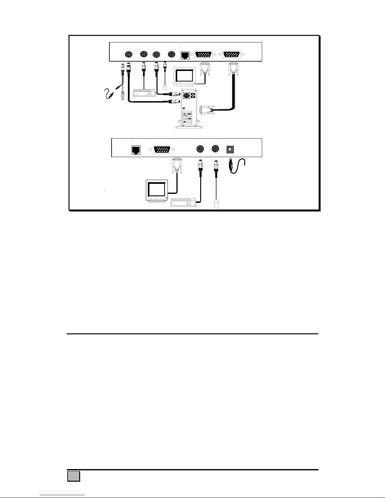
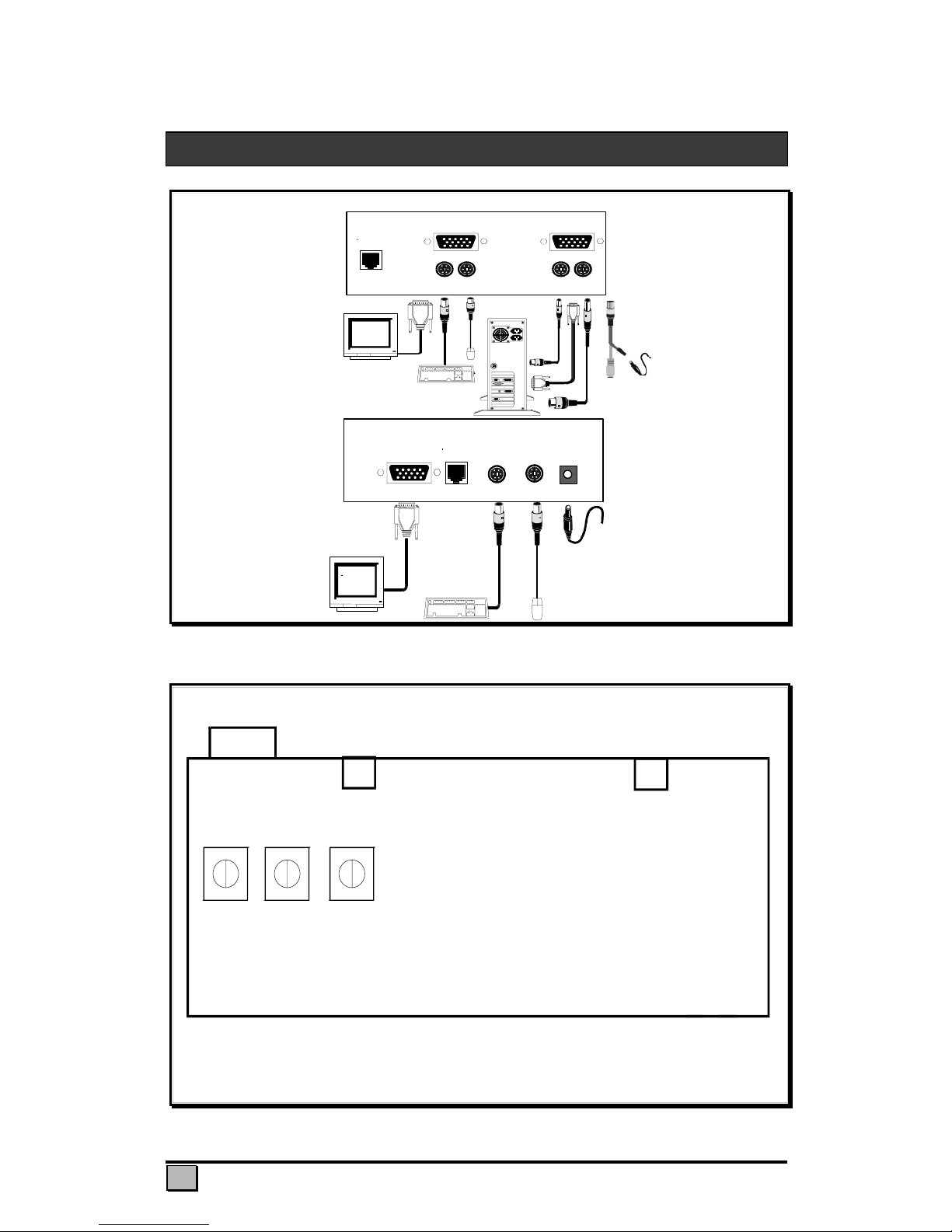
Power
Supply
Rear View of Remote Unit
UTP
Monitor Keyboard Mouse 9
–
12V DC
Remote
Rear View of Local Unit
UTP
KeyboardMouse
From PC
KeyboardMouse
User
Local
Optional 5VDC power supply
and adaptor cable
Voyager 60
Figure 1 Connecting the Voyager 60
Voyager 60
Remote Unit
5V DC
RJ45
VGA
Keyboard/Mouse
All three gain controls should be set identically. Rotating the
gain controls will adjust the brightness of the different colours
individually.
Figure 2 Remote Unit - RBG gain controls
QUICK SETUP SYSTEM GUIDE
ENGLISH
4
Power
Supply
UTP Rear View of Remote Unit
Monitor Keyboard Mouse 9
–
12V DC
Remote
Rear View of Local Unit
Keyboard
(
CPU
)
Keyboard Mouse
(
CPU
)
Mouse UTP Monitor
V
GA Output
(CPU)
Local
Optional 5VDC power supply
and adaptor cable
Voyager 300
Figure 3 Connecting the Voyager 300
Note—Voyager 125H does not have the dipswitches; it is not necessary to adjust
for cable length on these models, only gain and equalizaton.
Important note on power supplies/mains adapters--
The local unit (all Voyager models) is normally powered from the keyboard connector.
Some PC’s do not supply enough power from the keyboard connector; this necessitates
the use of a 5vdc mains adapter on the local unit. The Voyager 60 is equipped with a
DC jack for this purpose; this jack is normally not used, since most PC-s supply enough
power through the keyboard connector. The Voyager 125H/300 must be connected
with a special PS2/DC adapter Y- cable which allows connection of both mains adapter
and keyboard cable through the local unit’s PC keyboard connector.
Procedure
We recommend that the complete system be tested in one room before permanent
installation. If a long interconnect cable is not available, use a patch lead to test
basic unit operation with your PC.
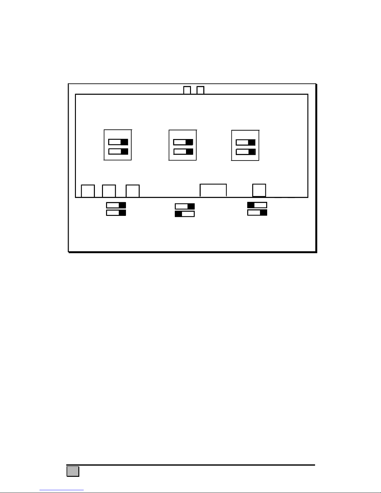
Step 1: Setting the Cable Length Dipswitches
The Voyager 60 has three gain controls to adjust gain, brightness and cable length
located on the underside of the device. The Voyager 125H use only the
equalization/gain controls and brightness on the front panel. The Voyager 300
compensates the cable length through the dipswitches on the underside of the device.
The Voyager 300 also has two rotary controls on the front panel to precisely alter the
compensation level and so ‘tunes in’ the image precisely for the cable length used.
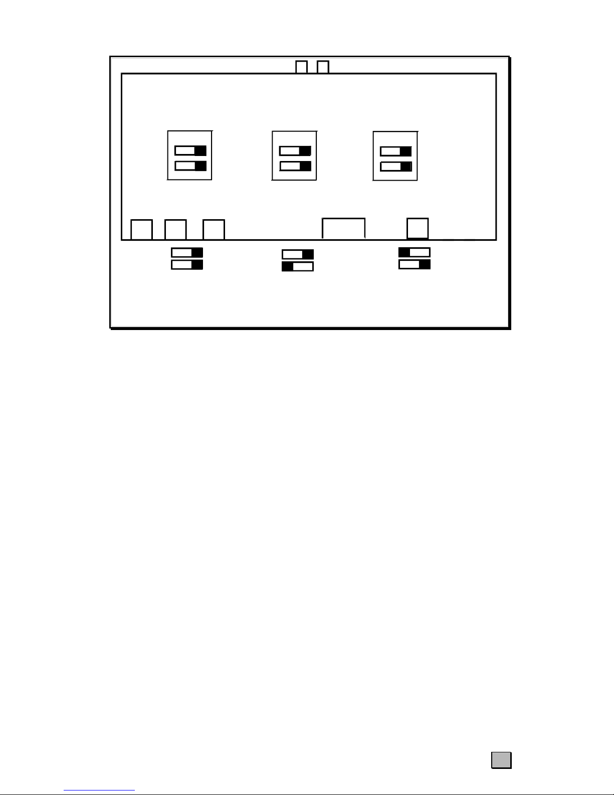
The three cable length dipswitch sets should be set as follows:
ENGLISH 5
V
oyager 300
Remote Unit
9V DC RJ45KEYBOARD
Gain
EQ
Position
A
Cable Length
100
–
200m/300
–
650ft
Position B
Cable Length
200
–
300m/650 – 1000ft
Default
Cable Length
0 – 100m/0 – 300ft
All three dip switch sets must be set to the same position.
< /
V
GA OutputMOUSE
< /
1
2
1
2
1
2
1
2
1
2
1
2
ON ON
ON
Figure 4 Remote Unit - Cable length dipswitches on the Voyager 300 (not found on other models)
If you are conducting a test in one room prior to final installation, set the dipswitch sets
as appropriate for the test cable length. Please ensure that all dip switches are set to the
same position.
Step 2: Connecting Up
Figure 1 & 3, illustrates how the units are interconnected.
1. Switch off your PC and connect up the Voyager, keyboard, monitor and mouse as
shown in the appropriate diagram.
2. Set the ‘Gain’ control (Voyager 125H/300 only) on the Remote Unit about midway,
and set the ‘EQ’ control fully counter-clockwise (no video compensation)
3. Power up the Remote Unit by connecting the mains adapter and switching it on.
Only use the mains adapter supplied.
4. Power on your PC and check that the keyboard operates correctly.
Note: The video image quality may be poor at this point.
5. Boot an operating system (such as Windows) or application you intend to use.
Check that the mouse functions (if required).
Step 3: Adjusting the Video Compensation for cable length (Voyager 300 only)
1. Load an application you intend to use that requires a high screen resolution (such as
a Windows word processor).
2. If the video is under-compensated you will notice black smearing on the right-hand
edge of large horizontal objects such as title bars. The degradation becomes more
noticeable as cable length increases.
3. Look at a point on the monitor where the smearing is evident. Now, rotate the ‘EQ’
control clockwise until the smearing disappears and the edge becomes very bright
and too sharp. At this point and beyond the video is over-compensated.
4. Rotate the ‘EQ’ control back slightly until you reach a point where the edge looks at
it should be (no smearing or over sharpness). The compensation is now adjusted
ENGLISH
6
correctly for the length of interconnection cable used.
5. The ‘GAIN’ control is used to adjust the brightness of the overall picture. After
adjusting this control to suit, the ‘EQ’ control may need a very slight readjustment.
6. The picture quality can be improved additionally by adding a skew compensation
device to adjust for Cat5/Cat6 skew delay factors, i.e. variable twisted pair lengths
resulting from differing twist ratios (intended for decreasing crosstalk in digital
transmission contexts). Skew compensation devices are available from Daxten or
through your dealer.
Please note that for all practical purposes cable equalisation cannot be exact - the
remote image will never be as sharp as the original. The Voyager’s equalisation system
is designed so that is produces very good results on short to medium length cables and
an acceptable quality over longer cables.
TIP: If you are at the top end of a cable length range, say 80m(260ft), and you are
using high resolution (1024x768 or more) you may achieve better quality video
compensation by selecting the next cable length range.
Keyboard & Mouse Emulation
The Voyager uses a microprocessor to emulate the keyboard and mouse. A keyboard
and mouse must be plugged into the remote unit at boot-up. It is not necessary to have
any keyboard or mouse connected to local unit either at start-up or during use.
Local / Remote Console Switching
The Voyager allows you to connect an additional keyboard, monitor, and mouse to
your system through the local unit. The PC may now be operated from either of two
locations though not simultaneously.
Pressing any key on the keyboard activates a console but the key press is ignored.
When the console is active, the other console cannot be operated. If the active console’s
keyboard or mouse is not used for more than 2 seconds, console switching may occur.
All versions of the Voyager 125H/300 offer a Private Mode whereby the remote
console can be locked, preventing access from the other console. The Voyager 60 does
not have this feature. The commands work only from the local unit.
Mode 1: The remote unit is locked, preventing any access. (Voyager 125H/300 only)
Activate by pressing <CTRL><ALT><F10>
Mode 2: The remote monitor is active, but the keyboard and mouse are locked.
Activate by pressing <CTRL><ALT><F11>
These commands can be cancelled by pressing <CTRL><ALT><F12>
OPERATION
ENGLISH 7
UTP / STP Connection Cable Wiring
The Local-Remote interconnection cable is terminated in RJ45 connectors and should
be wired according to the EIA/TIA 568 (Scheme B preferred) industry standard.
Pin Wire Colour Wire Pair
1 White/Orange T2
2 Orange/White R2
3 White/Green T3
4 Blue/White R1
5 White/Blue T1
6 Green/White R3
7 White/Brown T4
8 Brown/White R4
The Voyager has been tested with all major makes of CAT 5 cable including BICC-
VERO, Mohawk, and AT&T. The Voyager has also been tested with most major
makes of CAT 5E/6 with good results.
Keyboard
• The PC boots fine with no error messages, but the remote keyboard does not
work at all
a) Cable is loose, re-seat keyboard cable.
b) Wrong cable plugged in, keyboard and mouse cables reversed.
c) Try a different keyboard model. If the new keyboard works then the original one
may be incompatible (some older auto-sensing units may not work with this
product).
• Wrong or missing characters from those typed.
a) The keyboard may be in the wrong mode.
b) Power down and reboot the entire system or
c) Try ctrl-alt-f12 from the remote unit
• The PC always comes up with ‘Keyboard Error ’
a) If the system appears to work fine after pressing F1 (or ESC) adjust your BIOS set-
up so that the PC does not test the keyboard.
• Connecting a keyboard to the unit affects the Video.
a) Change to a newer keyboard. Some older keyboards require a high current.
PS/2 Mouse
• A mouse cursor on the screen, but the mouse does not work
a) Cable is loose, re-seat mouse cable and press ‘Scroll Lock’
b) Wrong cable plugged in, keyboard and mouse cables reversed.
TROUBLE SHOOTING
ENGLISH
8
c) Try a different model of mouse.
d) Power cycle the remote unit.
• The system does not detect a PS/2 mouse, or the application cannot find the
mouse.
a) Wrong cable plugged in, keyboard and mouse cables reversed on Local Unit.
b) Cable is loose, re-seat mouse cable between Local Unit and CPU.
c) Ensure that the keyboard input cable to the Local Unit is connected to provide
power.
d) Reboot PC.
• The mouse movement is erratic
a) Try installing a Microsoft Intellimouse mouse driver, which can automatically
correct out of sync mice.
Keyboard & Mouse
• Neither the keyboard or mouse operate, or have locked up
a) Press <CTRL><ALT><F12> on the remote unit to reset the keyboard and mouse
b) Reset PC and the Extender Remote unit.
c) Check power to the remote unit.
d) Some PC’s have a port re-mapping feature that allows a keyboard or mouse to be
plugged into either PS/2 port. Try crossing over the cables between the local unit
and PC i.e. KB to Mouse & Mouse to KB.
Video
• The picture is not sharp & is very smeary
a) Video compensation incorrectly set. - See installation section.
• Each character has separated into overlapping red, green & blue pixels, (the
effect is like looking through 3D glasses).
a) Check that the UTP / STP wiring used throughout is EIA 568 standard.
b) Check patch panels for poor or incorrect connections
c) Check the compensation dipswitch settings.
• The monitor sometimes loses sync causing it to go blank for a second or two
a) This occurs if your electrical power system is very noisy (particularly ground).
• Video only required, but no picture appears
a) The Local Unit must be connected to the PC’s keyboard port.
b) Consult technical support if you cannot do this and require a secondary power
supply for the Local Unit.
• A constant vertical wobble appears down the screen (interference).
a) The interconnection cable could be located too close to a source of very strong
mains borne interference, re-route cabling if possible
b) If interference is from strong signals from a nearby broadcast transmitter a beat
pattern will appear. Change the vertical refresh rates slightly, such as from 60Hz to
70Hz.

ENGLISH 9
• Video Picture is black and white not colour
a) You system requires a monitor ID code to boot into the correct video mode. Please
contact technical support on details to correct this.
• Windows or Windows NT will only boot into a low-resolution graphics mode.
a) The problem could be Monitor ID. See above.
b) If your graphics card supports VESA DDC (Display Data Channel) configure the
graphics driver by explicitly telling it which make and model of monitor you have
rather than using DDC.
• Is it possible to use a cable length of more than 300m?
The Voyager has been designed to produce acceptable results with Super VGA
resolutions at the maximum cable length. It may be possible to run up to 500m
(Voyager 300 only) at the standard VGA resolution (640x480). However, we cannot
guarantee that this will work in every instance.
• Can Voyager units be chained to allow operation over more than 300m/1000ft?
No, the chaining is not possible.
• Which cable is better UTP or STP?
UTP cable will give the best quality video over long distances because it has less
capacitance per unit length. However, STP may be a better choice in electrically noisy
environments. The Voyager 125H is optimized for both UTP and STP.
• When using UTP what is the best way to ensure the system does not suffer from
any interference?
This product is designed to withstand high levels of interference whilst using UTP over
long distances. To further reduce the potential for interference consider the following:
a) Ensuring that the computer and remote monitor are both connected to the same
mains phase.
b) Ensuring that the AC voltage across the mains grounds (at the local PC & remote
monitor) is less than 2V.
c) Using a clean earth system (if your site has one installed).
d) Routing the interconnection cable away from other cables.
e) Trying STP cable if you think noise could be a problem.
• Is the Voyager suitable for use between buildings?
The Voyager does not have line isolation. Therefore, operation between buildings is not
recommended.
• Is the Voyager connectable to my network?
The Voyager uses the same cable as your network, but it cannot be connected into your
network in any way. The Voyager must have dedicated cables in the network.
GENERAL QUESTIONS

ENGLISH
10
Connecting other equipment on the same cables as the Voyager voids the
guarantee and may damage the Voyager.
Maintenance and repair
The unit does not contain any user-serviceable parts inside. Any malfunction of the unit
should be reported to a factory-authorised repair centre for service. Any discrepancies
in the operation of the unit according to this manual should be reported to the Technical
Support Department of Daxten.
Technical support
If you cannot determine the nature of a problem, please call Daxten and ask for
Technical Support. If possible call from a phone located near the unit we may be able
to solve your problem directly over the phone. If we cannot solve your problem, and
determine that the fault is in the unit, we will issue a Return Material Authorisation
(RMA) number that must appear on the outside of all returned products. The unit
should be double-packed in the original container, insured, and shipped to the address
given to you by our Technical Support representative.
SERVICE INFORMATION

ENGLISH 11
Size Voyager 300/125H
Local & Remote Units:
210 x 100 x 45 mm (8.27 x 3.94 x 1.77 in.)
Voyager 60
Local & Remote Units:
125 x 95 x 45mm (4.92 x 3.74 x 1.77 in.)
Weight Voyager 60 – 1.25Kg (2.76lbs)
Voyager 300 – 1.75 Kg (3.86lbs)
Input Power Local Unit: from PC or optional 5V DC 1A PSU
Remote Unit: 9V DC regulated, 1.3A
Interconnect Cable CAT 5, CAT 5E, Cat 6 Solid UTP/STP
EIA/TIA 568 Wiring
RJ45 Connectors
Video Bandwidth (-3dB) Local Unit: 150MHz
Remote Unit: 60 / 300 MHz
Maximum Resolution
(Skew compensation may be
required with CAT5E or CAT6
cables for comparable quality)
1280 x 1024 Voyager 60
1600 x 1200 Voyager 125H
1280 x 1024 up to 150 m Voyager 300
1024 x 768 up to 300 m Voyager 300
Video I/O 0.7V P-P
Video Compatibility VGA, Super VGA, XGA
Video Compensation 3-Stages in 3 Ranges
Video Coupling DC
Sync I/O Separate/Composite TTL level
Keyboard Compatibility PS/2
Mouse Compatibility Standard PS/2 2 Button, Microsoft Intellimouse
and Logitech PS/2 3 Button
Console Lockout Time Period 2 seconds
APPENDIX A. GENERAL SPECIFICATIONS
DEUTSCH 13
GEWÄHRLEISTUNGSBEDINGUNGEN
Daxten GmbH garantiert die volle Verfügbarkeit des Voyager 60/125H/300 für zwei Jahre, gerechnet
von der Auslieferung durch Daxten oder einem autorisierten Händler. Sollte das Produkt während der
zweijährigen Gewährleistungsfrist technisch versagen, wird Daxten auf seine Rechnung das Produkt wie
im Weiteren beschrieben instandsetzen oder umtauschen. Zu reparierende Teile oder auszutauschende
Komponenten werden entweder instandgesetzt oder durch neue ersetzt. Sämtliche ersetzten Teile oder
Komponenten gehen in das Eigentum von Daxten über. Die Gewährleistung erstreckt sich nicht auf den
gewöhnlichen Reparaturservice, d.h. wenn der Schaden am Gerät oder einzelnen Komponenten bzw.
Teilen durch Unfall, höhere Gewalt, missbräuchliche Verwendung oder unautorisierten Modifikationen
am Gerät, einschließlich statischer Auf- und Entladung, Überspannung und Spannungsspitzen, zustande
kam.
Die Gewährleistung kann in Anspruch genommen werden, indem das Gerät während der zweijährigen
Gewährleistungsfrist zu Daxten oder einem von Daxten autorisierten Reparaturbetrieb mit einem
Nachweis des Kaufdatums eingesandt wird. Falls das Gerät auf dem Postwege versandt wird, erklären
Sie sich damit einverstanden das Gerät entweder selbst zu versichern oder das durch den Transport
entstehende Risiko des Verlusts oder Schadens am Gerät selbst zu tragen, ferner die Versandkosten zum
Serviceort im voraus zu bezahlen und die Originalverpackung oder eine vergleichbar geeignete
Verpackung zu benutzen. Vor dem Rücktransport müssen Sie auf jeden Fall zuerst eine
Rücknahmenummer (RMA) von Daxten anfordern. Unter keinen Umständen wird ein zurückgeschicktes
Gerät ohne Rücknahmenummer akzeptiert. Wenden Sie sich bitte an Daxten oder an einen von Daxten
autorisierten Reparaturbetrieb, wenn Sie weiterführende Informationen erhalten wollen.
Alle ausdrücklichen und impliziten Garantien, einschließlich die Gewährleistung der
Handelsfähigkeit und die Eignung für einen speziellen Zweck sind auf den Gewährleistungszeitraum
von zwei Jahen beschränkt, beginnend vom Tag der Auslieferung, und es findet keine
Gewährleistung, weder explizit noch implizit, nach Ablauf der Gewährleistungsfrist mehr statt. Einige
Länder erlauben keine zeitliche Limitierung der impliziten Gewährleistung, deshalb findet die obige
Einschränkung für Sie gegebenenfalls keine Anwendung.
Falls das Produkt nach seiner Auslieferung nicht wie oben garantiert voll funktionsfähig ist, ist die
einzige Wiedergutmachung ein Ersatz oder eine Reparatur. In keinem Fall übernimmt Daxten die
Haftung für eventuelle Schäden, einschließlich entgangener Einkünfte, verlorener Ersparnisse oder
anderer sich einstellender oder resultierender Schadensersatzansprüche, die sich aus dem Gebrauch
oder der Nichtbenutzbarkeit dieses Produkts ergeben, auch wenn Sie von Daxten oder einem von
Daxten autorisiertem Händler auf die Möglichkeit eines Schadens aufmerksam gemacht wurden.
Ebenso wenig gibt es eine Haftung im Falle irgendwelcher Ansprüche irgendeiner Partei.
Kein Teil dieser Bedienungsanleitung darf in irgendeiner Form (Druck, Fotokopie oder einem anderen Verfahren)
ohne die schriftliche Genehmigung von Daxten reproduziert oder unter Verwendung elektronischer Systeme
gespeichert, verarbeitet, vervielfältigt oder verbreitet werden.
IBM ® AT, und PS/2 sind eingetragene Warenzeichen der International Business Machines Corp.
Microsoft ® und Microsoft Windows ™ sind eingetragene Warenzeichen von Microsoft Corp.
Multisync ist ein Warenzeichen der NEC Technologies, Inc.
Alle anderen Produkte sind Warenzeichen oder eingetragene Warenzeichen ihrer jeweiligen Eigentümer.
© Copyright 2003. All rights reserved.
Printed in Ireland Revision 4.0 Manual Part No: 8034-00-DE
HINWEIS: Dieses Gerät entspricht den Anforderungen der Richtlinie 89/336/EWG der
europäischen Gemeinschaft, insbesondere den Teilen EN55022 Klasse B, EN
50082-1 und EN 60555-2.
DEUTSCH
14
Vielen Dank, daß Sie sich für den Voyager 60 / Voyager 125H oder Voyager 300 entschieden
haben. Entworfen für eine ‘Plug & Play’-Handhabung, erlaubt Ihnen der neue Voyager die
Bedienung Ihrer PC-Systemeinheit durch Tastatur, Monitor und PS/2-Maus aus bis zu 300
Metern Entfernung.
Eigenschaften
Dieses Produkt verfügt über eine Anzahl von einzigartigen Leistungsmerkmalen, die es Ihnen
gestatten, Ihrem PC fern zu bedienen.
• Zugriff auf Ihre CPU aus bis zu 60m (Voyager 60) oder 300m (Voyager 300) und 125m
(Voyager 125H) Entfernung bei Nutzung eines CAT 5, 5E oder 6 twisted Pair Kabels.
• Voll justierbare(r) Videoverstärkung und –Abgleich (nur Voyager 300/125H)
Sie gleicht einen möglichen Verlust an Bildqualität, bedingt durch die Kabellänge, aus.
• Separate justierbare Verstärkung im Grün-, Gelb- und Blaumodus (RGB) (nur Voyager 60)
• Voll gepufferte Signale
Sie stellen eine sichere Fernbedienung Ihres PCs her.
• PS/2-Tastatur und PS/2-Maus-Emulation
Die intelligente Tastatur- und Mausemulation erlaubt ein korrektes Hochfahren und
korrektes Arbeiten Ihres PCs unter allen nur denkbaren Umständen, sowie eine ‘Plug &
Play’-Initialisierung Ihrer entfernten Tastatur und Maus.
• Dual Access-Funktion
Sie haben zusätzlich die Möglichkeit, einen Monitor, eine Tastatur und eine Maus an der
Lokalkomponente anzuschließen und Ihren PC wahlweise lokal oder entfernt zu bedienen.
Bedienung
Der Voyager ist einfach zu handhaben und arbeitet mit allen Betriebssystemen (Kompatible
Betriebssysteme siehe Seite 6). Er verlangt keine zusätzlich installierte Software. Stecken Sie
einfach die Komponenten wie beschrieben zusammen, und Sie können mit dem Arbeiten
beginnen.
Kompatibilität
Um in verschiedenen Umgebungen sowie mit der Hardware von verschiedenen Herstellern
arbeiten zu können, besitzt dieses Produkt eine Anzahl von spezifischen Leistungsmerkmalen.
Das Produkt wurde mit einer Vielzahl von Hardware getestet. Es ist jedoch nicht möglich eine
Garantie für eine reibungslose Bedienung mit jeder Tastatur, jeder Maus, und jedem Monitor,
die erhältlich sind, zu übernehmen. Sollten sie ein Problem mit einer bestimmten Hardware
haben, kontaktieren Sie uns und wir werden versuchen das Problem zu lösen.
Der Voyager ist jedoch garantiert kompatibel mit folgender Ausrüstung:
• Systemeinheit: PS/2 und 100% kompatible Nachbildungen
• Tastatur: PS/2
• Maus: PS/2-Maus, MS IntelliMouse, Logitech 3 Tasten
• Monitor: VGA, Super VGA, XGA
EINFÜHRUNG

DEUTSCH 15
Dieser Abschnitt beschreibt die Installation und Arbeitsweise des Voyager
Ihre Voyager-Lieferung enthält folgende Komponenten
1 Voyager 60 / Voyager 300/ Voyager 125H Lokalkomponente
1 Voyager 60 / Voyager 300/ Voyager 125H Fernkomponente
1 Netzteil*
1 CPU Cable Set
1 User Manual
* Benutzen Sie nur das mitgelieferte Netzteil.
Beachten Sie — Der Voyager 60 benötigt eine 5 VDC Stromversorgung an der Lokal- sowie
Fernkomponente (optional an der lokalen), der Voyager 125H/300 benötigt eine 9 VDC
Stromversorgung an der Fernkomponente und eine 5 VDC an der lokalen (an der
Lokalkomponente ist die Stromversorgung optional und benötigt ein spezielles PS/2
Netzkabel)
Erforderliche Kabel
Die Kabel für den Anschluss der Lokalkomponente des Voyager an Ihren PC werden
mitgeliefert.
Ihre Tastatur, den Monitor und die Maus schließen Sie bitte direkt an die Voyager -
Fernkomponente an. Die Fernkomponente wird mit der Lokalkomponente mittels eines
standardisierten Kabels für Industriezwecke (Kategorie 5 UTP/STP, 4-Paar) mit einem RJ45-
Anschluß verbunden. Dieses Kabel wird nicht mitgeliefert. Sofern Sie nicht im Besitz eines
passenden CAT 5 UTP- oder STP-Kabels sind, das unseren Anforderungen der entspricht,
setzen Sie sich bitte mit Ihrem Händler in Verbindung.
Folgende Punkte sind bei diesem Verbindungskabel unbedingt zu berücksichtigen:
1. Das verwendete Kabel sollte aus massiven Volldrahtleitern bestehen.
Flexible Litzenkabel werden selbst bei kürzeren Entfernungen eine schlechtere Bildqualität
liefern als massive Volldrahtleiter.
2. Die Anschlußverbindung muß dem Standard EIA/TIA 568B entsprechen.
Verwiesen sei auch auf die hinteren Seiten im Handbuch.
.
Hinweis: Falsch angeschlossene Kabel verschlechtern die Bildqualität dramatisch und
können unter Umständen die Voyager zerstören.
Der Voyager ist für eine Kabellänge bis zu 60 (Voyager 60), 125 (Voyager 125H) oder 300
(Voyager 300) Metern ausgelegt. Bei dieser Distanz sollte die Bildschirmauflösung von 1024 x
768 @ 75Hz und 1600 x 1280 (Voyager 125H) akzeptabel sein.
Obwohl ein durchgängiges Kabel bevorzugt werden sollte, ist es dennoch möglich das Kabel
über Patch-Panels zu führen. Jede Patchstelle wird die Qualität des Videosignals
beeinträchtigen.
WIE SIE BEGINNEN
DEUTSCH
16
Netz
Kabel
Rückansicht Remote Einheit
UTP
Monitor Tastatur Maus 9
–
12V DC
Remote
Rückansicht lokale Einheit
UTP
Tastatur Maus
vom PC
Tastatur Maus
Benutzer
Lokal
Optional 5VDC Netzkabel
und Adapter
Voyager 60
Abbildung 1: Verkabelung des Voyager 60
V
oyager 60
Remote Einheit
5V DC
RJ45
VGA
Tastatur/Maus
Die drei Drehregler sollten identisch eingestellt sein. Durch das
Drehen an den Reglern können Sie die Helligkeit der Farben
definieren.
Abbildung 2: Remote Einheit - RBG Drehregler
SCHNELLE INBETRIEBNAHME

DEUTSCH 17
Netz
Kabel
UTP Rückansicht der Remote Einheit
Monitor Tastatur Maus 9
–
12V DC
Remote
Rückansicht lokale Einheit
Tastatur
(
CPU
)
Tastatur Maus
(
CPU
)
Maus UTP Monitor
V
GA Output
(CPU)
Lokal
Optional 5VDC Netzkabel
und Adapter
Voyager 300
Abbildung 3 Verkabelung des Voyager 300
Beachten Sie — Der Voyager 125H benötigt keine DIP Switches; es ist nicht
notwendig die Kabellängen an diesem Gerät einzustellen, nur Videoverstärkung
und Abgleich
Wichtiger Hinweis zur Stromversorgung
Die Lokalkomponente aller Voyager Modelle wird normalerweise über die Tastatur-
schnittstelle versorgt. Einige PC’s verfügen jedoch nicht über eine ausreichende Strom-
versorgung über die Tastaturschnittstelle. In diesem Fall benötigen Sie einen 5 V-DC
Netzadapter an der Lokalkomponente. Der Voyager 60 ist mit einer DC Buchse ausgestattet.
Diese Buchse wird normalerweise nicht benötigt, da die meisten PC’s über eine ausreichende
Stromversorgung von der Tastaturverbindung verfügen. Der Voyager 125H/300 muss mit
einem speziellen Y PS/2/DC Adapter verbunden werden. Diese Kabelverbindung ermöglicht
die gleichzeitige Verbindung des Netzadapters und des Tastaturkabels mit der an der lokalen
Tastaturverbindung.
Installation
Wir schlagen vor, dass Sie das komplette System in einem Raum testen, bevor Sie es
endgültig installieren. Falls kein langes Verbindungskabel zur Hand ist, benutzen Sie ein
kurzes Kabel (Patch-Kabel), um die grundlegende Zusammenarbeit zwischen dem Gerät
und Ihrem PC zu testen.
Schritt 1: Setzen der DIP-Switches zum Einstellen der Kabellänge über die
Fernkomponente
Der Voyager 60 kompensiert die Kabellänge, Videoverstärkung, -abgleich und Hellig-keit über
die Drehregler an der Unterseite des Gerätes.
Der Voyager 125H regelt nur die Videoverstärkung, -abgleich und Helligkeit über die
Drehregler an der Frontseite des Gerätes.
DEUTSCH
18
Der Voyager 300 kompensiert die Kabellänge über die DIP-Switches an der Unterseite,
Videoverstärkung, -abgleich, Helligkeit über Drehregler an der Frontseite des Gerätes
Wie die DIP Switches gesetzt werden, zeigt folgendes Schema:
V
oyager 300
Remote Einheit
9V DC RJ45TASTATUR
Gain
EQ
Position
A
Kabellänge
100
–
200m/300
–
650ft
Position B
Kabellänge
200
–
300m/650 – 1000ft
Voreinstellung
Kabellänge
0
–
100m/0
–
300ft
Die drei DIP Switches müssen in dieselbe Position gebracht werden
< /
V
GA OutputMAUS
< /
1
2
1
2
1
2
1
2
1
2
1
2
ON ON
ON
Abbildung 4 Remote Einheit - DIP Switches für die Kabellängen Voyager 300
Alle drei DIP-Switch Paare müssen sich in der selben Position befinden.
Setzen Sie die DIP-Switches auf die der Kabellänge entsprechende Einstellung.
Schritt 2: Verkabelung
Die Abbildungen 1 und 3 zeigen Ihnen, wie Sie die Komponenten untereinander verkabeln
müssen.
1. Schalten Sie Ihren PC aus, und schließen Sie an den Voyager, die Tastatur, den Monitor und
die Maus an, wie es in Abb.1 gezeigt wird.
2. Stellen Sie die ‘Gain’-Einstellung (nur Voyager 300) ungefähr mittig und die ‘EQ’-
Kontrolle entgegen dem Uhrzeigersinn ganz zurück (keine Videokompensation).
3. Versorgen Sie die Fernkomponente mit Spannung, indem Sie das Netzteil anschließen.
Benutzen Sie ausschließlich das mitgelieferte Netzteil !
4. Schalten Sie Ihren PC ein und vergewissern Sie sich, dass die Tastatur einwandfrei
funktioniert. Die Bildqualität kann bis zu diesem Moment schlecht sein.
5. Fahren Sie Ihr Betriebssystem (z. B. Windows) hoch, und stellen Sie sicher, dass die Maus
(falls Sie eine anzuschließen beabsichtigen) funktioniert.

DEUTSCH 19
Schritt 3: Justieren der Videokompensation am Voyager 300
1. Starten Sie eine Ihnen geläufige Applikation, die eine hohe Auflösung verlangt.
2. Falls das Videosignal unterkompensiert ist, werden Sie einen schwarzen Schatten
(Schmiereffekt) auf der rechten Seite horizontal gelagerter Objekte wie z. B. Kopfzeilen
bemerken. Die Videosignalabschwächung macht sich um so stärker bemerkbar, je länger die
Kabelverbindung ist.
3. Fixieren Sie den Punkt auf dem Monitor, an dem der Schmiereffekt auftritt. Jetzt drehen Sie
an der Fernkomponente die ‘EQ’-Kontrolle im Uhrzeigersinn, bis der Effekt verschwindet
und die Kante des Objekts sehr hell und scharf wird. An dieser Stelle und darüber ist das
Videosignal überkompensiert.
4. Drehen Sie die ‘EQ’-Kontrolle leicht zurück, bis Sie einen Punkt erreichen, an dem die
Kante so aussieht wie sie aussehen sollte, nämlich nicht verschmiert und nicht überscharf.
Die Kompensation ist jetzt in Bezug auf die Kabellänge korrekt eingestellt.
5. Die Signalverstärkung (‘Gain’) wird benutzt, um die Helligkeit des ganzen Bildes zu
justieren. Nachdem Sie diese passend justiert haben, kann eine ganz leichte Nachjustierung
der ‘EQ’-Kontrolle nötig sein.
6. Die Bildqualität kann durch Ergänzung einer Skew Compensation verbessert werden. Die
Skew Compensation reguliert Laufzeitunterschiede zwischen den Daten- und Taktsignalen,
die durch ungleiche Kabellängen beim Cat5/Cat6 Kabel (twisted pair) hervorgerufen werden
können. Geräte zur Skew Compensation erhalten Sie bei Daxten oder Ihrem Händler.
Hinweis:Aus naheliegenden Gründen ist der Videoabgleich niemals ganz exakt - deshalb
kann das Fernbild nie so scharf sein wie das Original.
Der Voyager UTP-Systemabgleich ist so ausgelegt, daß er sehr gute Resultate auf kurzen und
mittleren Distanzen liefert und auf längeren eine akzeptable.
TIP: Falls Sie mit Ihrer Kabellänge z. B. bei 80 Meter liegen und eine hohe Auflösung
(1024x768 und mehr) benutzen, können Sie möglicherweise eine bessere Qualität in Ihrer
Videokompensation erreichen, wenn Sie die Stufe für die nächstgrößere Kabellänge einstellen.
Tastatur- & Maus-Emulation
Der Voyager benutzt einen Mikroprozessor, um die Tastatur und Maus für den angeschlossenen
Rechner zu emulieren. Beim Bootvorgang des Rechners müssen Tastatur und Maus an der
Fernkomponente des Voyager angeschlossen sein. An der Lokalkomponente müssen weder
Tastatur noch Maus angeschlossen sein.
Umschalten von Lokal- und Fernkonsole
Der Voyager erlaubt es Ihnen, zusätzlich einen Monitor, eine Tastatur und eine Maus an Ihr
System an die Lokalkomponente anzuschließen. Der PC kann dann von einer der beiden Stellen
bedient werden, nicht jedoch gleichzeitig von beiden.
Die eine der beiden Konsolen wird aktiviert, indem eine beliebige Taste der Tastatur gedrückt
wird, oder die angeschlossene Maus bewegt wird. Das abgesetzte Zeichen wird ignoriert, die
damit angewählte Konsole ist jetzt betriebsbereit. Die andere Konsole kann während dieser Zeit
nicht bedient werden.
Wenn die Tastatur oder Maus der aktiven Konsole mehr als 2 Sekunden nicht benutzt wurde,
BETRIEB
This manual suits for next models
2
Table of contents
Languages:
Other Daxten Extender manuals

Daxten
Daxten VOYAGER DVI EXTENDER User manual

Daxten
Daxten Vojager USB Lite User manual

Daxten
Daxten VOYAGER UTP EXTENDER User manual

Daxten
Daxten GE-EXT-FW-1394 User manual

Daxten
Daxten VOYAGER SERIAL User manual

Daxten
Daxten Voyager 100 Operating manual

Daxten
Daxten VOYAGER DVI EXTENDER User manual

Daxten
Daxten Voyager 300 User manual

Daxten
Daxten LONGVIEW 1000 User manual

Daxten
Daxten VoyagerTouch 60 User manual


