PROCET PT-PIS4PB1S-M User manual

PT-PIS4PB1S-M PoE Switch
www.procetpoe.com
Quick Installation Guide

Declaration
Declaration
The symbol indicates that the product should not be discarded as
unsorted waste but must be sent to separate collection facilities for recovery
Copyright©2022 Creative Lianjie Network Technology Co.Ltd
This document belongs to PROCET company. It is not allowed to reproduce
and modify without the original author's permission. It is PROCET's policy to
improve its products as new technology, components, software, and firmware
at any time. PROCET, therefore, reserves the right to change specifications
without prior notice. Please follow WEEE (Waste Electrical and Electronic
Equipment) disposal instructions for old electronic products. Please do not
dispose of the old product in your general household waste bin.
All rights reserved.
and recycling.

Overview
Overview
For Whom
Network Engineers
Network Administrators
The installation Guide for PT-PIS4PB1S-M and mainly introduces the hardware
specification, installation methods, and precautions of the installation.
There may be differences in the appearance and configuration from other
models. All product images in this manual are for illustration purposes only
and may differ from the actual product.
This manual includes the following chapters:
1. Product Introduction. Including the basic functions and specification of
PT-PIS4PB1S-M, as well as the product appearance and applications
introduction.
2. Installation Introduction. Introducing the preparation work and
precautionsbefore installing the product.
3. Product Installation. Two methods of product installation.
Field Technicians

2.1 Package contents........................................................06
2.2 Installation tookit........................................................06
2.3 Inspection
1.1 Introduction..................................................................01
1.2 Appearance...................................................................01
1.3 Specification.................................................................03
1.4 Management Interface
Table of contents
.............................................04
.......................................................................06
Table of Contents
1.Introduction 01
2.Installation Preparation 06
3.1 Installing in waterproof case....................................08
3.2 Connection....................................................................10
3.3 Grounding......................................................................10
3.4 Inspection.......................................................................12
3.Installation 08

Introduction 01
1. Introduction
1.1 Introduction
1.2 Appearance
Upper View
PT-PIS4PB1S-M, an industrial 4-port PoE switch with Managed Ethernet
function. Supports IEEE 802.1Q VLAN and port-based VLAN. We can access
and manage the device via web browser, including IP configuration, port
configuration, VLAN configuration, PoE configuration, factory reset, etc. We
can also view device information, such as switch status, port status, PoE
status, etc. In addition, the PoE port enables remote control of the
device' on/off.
Equipped detecting chip inside which will make the PoE identification
handshake with IEEE802.3af/at/bt PDs.Such as PTZ cameras, wireless APs,
base stations, and other PoE-powered devices which need high power watts.
Protecting non-PoE powered devices. Each PoE output port delivers 1.75A
up to 90W(max) power for remote PDs over 4 pairs.
One fiber slot only supports 1000Mbps of optical module, while RJ45
copper port supports 10/100/1000Mbps. Enclosed in an IP40 high-impact
metal case with a DIN Rail mount bracket, designed for indoor use but can
work outdoors by covering it with a waterproof case. It works with an input
voltage of 48-57Vdc and operates under -40°to +65°. For planning
purposes, the effective distance is 100 meters over Cat5/5e/6 cables.
1-1 Upper View
DC Input Port
DIN Rail Bracket
GND Terminal

1-2
02 Introduction
Side View
1-3 Front View
Side View
Front View
Data Indicator
SFP Input Port
DC Power Indicator
PoE Output Port
PoE Load Indicator
SFP Indicator

Introduction 03
1.3 Specification
PoE Load
Indicator
Green
Data
Indicator
Yellow
Items Status
Solid Light
Flashing Light
Solid Light
Flashing Light
Light Off
Detecting PD
If flashing all the time, the PD may not
PoE Switch is powered off/defective
PoE Indicator Display:
.
Data is being transferred.
Data available(Normal).
be 802.3af/at/bt standard.
PD is powered( Default/Normal ).
Description
Items
Input
De
IEEE802.3af/at/bt
PoE Standard
46-57Vdc 1.75A, Each Port: 90W(Max)
4/5(+), 7/8(-) & 3/6(+), 1/2(-)
scription
PoE Surge Protection
Output
Power Pins
5%-95%,non-condensation
Up to 5000 meters
-40℃-70℃
10%-90%,non-condensation
IEEE802.3i / IEEE802.3u / IEEE802.3ab / IEEE802.3z
RJ45:10/100/1000Mbps SFP:
144.5mm×95mm×35.4mm(483g)
1G
CE FCC
IP40
Network Protocol
Data Speed
IP Rated
Regulatory Compliance
Dimensions & NW
48-57Vdc 7.5A
EN 55032:2015/A11:2020
EN 55035:2017/A11:2020
EMC
Storage Humidity
Storage Temp.
Operating Altitude
Operating Humidity
Work Temp. -40℃ to 65℃
Protected line:1,2,3,4,5,6,7,8
Common mode surge protection(10/700us): 6kV
Differential mode surge protection (10/700us): 1.5KV

04 Management Interface
When all network connection is completed, run web browser on the
computer, type in the address field, for example, 192.168.1.151, then
press ENTER for opening the login page. Log into the system with a
username and password. The login page is displayed in the below pic.
Caution: Make sure the computer must be set on the same IP subnet
address as the PoE managed switch. Such as 192.168.1.*
1.4 Web
After entering the username and password, the main screen appears as
below figure.
There are Switch Menu on the left of the web page, including System
Information, IP Address, Account Information, Port, VLAN, PoE, Reset
configuration, and Reboot.
Management

Management Interface 05
The current device supports VLAN segmentation function. Users can
flexibly segment the VLAN according to demand.
This Page supports the PoE configuration function, disables or
enables PoE port, displays per PoE port power consumption, voltage,
current, and Class level information.

06 Installation Preparation
2. Installation Preparation
2.1 Package contents
2.2 Installation toolkit
These tools may be needed during equipment installation, and
should be prepared by yourself: level ruler, marking pen, craft knife,
wire stripper, network pliers, impact drill,different matching drilbits,
rubber hammer, cross screwdriver, wrench, ladder, etc.
2.3 Inspection
2.3.1 Connect the device to a DC Power System and check the PWR LED
to ensure proper function before installation.
2.3.2 Connect the PoE port to the PoE powered device(PD). Such as
the IP Cameras or Wireless APs.
As showed in Figure 2-1;
Caution:
Please use PoE powered device(PD) that complies with
IEEE802.3af/at/bt/PoE++ to connect this product.
!
Ground
lug Wire& 2.5
PT-PIS4PB1S-M Operation Manual
screw
Open the box of the PT-PIS4PB1S-M and carefully unpack it, the
box should contain the following items:

2-1
Installation Preparation 07
Device Connection
To ensure better lightning protection for outdoor PD,it is
recommended to use PROCET Ethernet surge protection products.
For more information, please visit http://www.procetpoe.com
!
Switch
SFP Port
Data Input
Power Input
PoE Data& Power
Output
PT-PIS4PB1S-M
PD
DC
Caution:
1. Please read the instructions carefully and follow the standard operating
procedures before using.
2. Please place it in a well-ventilated and dry area, and it is for indoor use only.
3. Connect the DC power cable to the Procet PoE switch. The DC connector is a
screw terminal block. Loosening and tight the screw by using a straight driver.
4. Connect a fiber-optic cable from your switch to this PoE switch SFP port for
fiber data transfer. The SFP fiber transceiver is not included in the package. The
current PoE switch supports single-mode and multi-mode fiber modules.
5. Connect a CAT5/5e/6 cable with the RJ45 connector into the RJ45 socket
labeled PoE. On the other end of the CAT5e/6 cable, connect to your PoE
Device (such as IP Cameras etc). The total Ethernet cable length can not
exceed 100 meters.
6. The device must be placed on a stable surface, preferably affixed and
mounted permanently. Do not leave it "dangling" and use plugged-in cables
in tension as support. Drops, falls, and impacts experienced by the injector
can compromise the internal components & cause premature failure.
7. Do not place heavy objects on top of this injector. Allow at least 5cm of
clearance on all sides of the device for heat ventilation / natural convection.
08 Installation
3. Installation
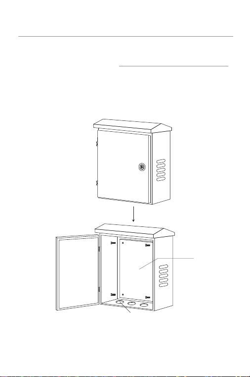
3.1.1 Install the waterproof case first, and keep the case open.
If it is placed in an outdoor environment, please install the device in a
waterproof case with a height of 45cm if possible.
As showed in 3-1.
3.1 Installation in waterproof case
Backplate
cable
3-1 Waterproof case
This product is safe to use for waterproof case installation and wall-mounted
installation.

Installation 09
3.1.3 Reinstall the backplate with the installed product into the
3.1.2 Remove the metal backplate from the waterproof case and fix
the DIN rail bracket on the backplate, then install this product on
DIN rail bracket.
waterproof case.
3-2 Installation
!
DIN Rail
Rail
Mounting
Screws
DIN Rail
Backplate
Caution:
Please use the expansion bolts, when you install the
product with wall-mounted way.

10 Installation
Caution:
Waterproof Ethernet cables should be with a
protective sheath. CAT5e/6 cables are recommended.
!
3.2 Connection
After installation is done, the next step is the connection. The following
precautions should be taken when connecting the Ethernet cable:
3.2.1 Lay the cable according to the design requirements. The cable
should be laid firmly and neatly, with no crossing, twisting, or cracking.
3.2.2 Do not lay the cable together with high-voltage pipelines, fire
pipelines, or building lightning protection systems to avoid interference
from strong electricity or magnetism.
3.2.3 Use PVC pipes, iron pipes, Prilka pipes, or cable trays for cable
laying. The cable trays should be placed against the wall, with neat and be
autiful routing. Soft hoses or elbow joints should be used at turning
points. The cable trays should be secured with cable ties, hangers, and
angle steels at a spacing of 1 to 1.5 meters. If a metal cable tray is used, it
should be grounded at both ends.
3.2.4 For outdoor horizontal wiring, please use a slot every 6 meters under
the PVC pipe as a drain to prevent water accumulation inside the pipe.
3.2.5 The wall penetration for the Ethernet cable should be sealed with
waterproof and flame-retardant materials.
3.3 Grounding
If the installation is in the computer room, it can be connected to the
dedicated grounding busbar in the room. The grounding busbar is a
connecting conductor between the grounding bodies of the building,
such as flat iron, flat steel, nanomaterial conductors, copper-clad steel,
etc.
PROCET PoE switch PT-PIS4PB1S-M has the following grounding
solutions for reference during construction:
Pls refer to the figure 3-3.

3-3
Installation 11
Grounding
GND Terminal
2.5 screw
Grounding Busbar
!
For the safety of personnel and equipment in an environment without
dedicated grounding equipment, a simple grounding device can
be constructed as follows:
a. Prepare a 6mm 2 grounding wire or a braided soft copper wire.
b. Prepare a copper tube or angleiron, or other metal tube, bury it
underground to a depth of one meter or more as a grounding
electrode.
c. Use the grounding wire to connect the external grounding terminal
of the product to the metal tube.(or angle iron)
Caution:
Use a galvanized metal pipe buried underground at a
depth of one meter or more, such as a water or
sew age pipe , as an emergency grounding if no
other grounding environment is available.

12 Installation
3.4 Inspection
2200
3-4 Simple Grounding
Ground
2.5 screw
MM
Soil
GND Terminal
Inspect the installed equipment before putting it into operation:
· Make sure the PD is compliant with our product.
· Make sure the Ethernet cable connection is correct.
Make sure all connections are correct, and turn on the power,
inspect all the indicators.

Qualication Card
PASS
Creative Lianjie Network Technology Co.Ltd
www.procetpoe.com
Other manuals for PT-PIS4PB1S-M
1
Other PROCET Switch manuals


Popular Switch manuals by other brands


Trust
Trust START-LINE APA3-1500R manual

Speaka Professional
Speaka Professional 350046 Operating intructions

Avaya
Avaya Cajun P550R installation guide

TP-Link
TP-Link HS200 user manual

Bühler technologies
Bühler technologies Nivotemp NT-M Series Installation and operation instructions

Cisco
Cisco Catalyst 1900 Series quick start guide


