Procomp BIW2A User manual

Safety and Regulatory Information
USA Notice
FCC Part 15:This equipment has been tested and found to comply with the
limits for a class B digital device, pursuant to Part 15 of the FCC Rules. These limits
are designed to provide reasonable protection against harmful interference in a resi-
dential installation. This equipment generates, uses, and can radiate radio frequency
energy and, if not installed and used in accordance with the instructions, may cause
harmful interference to radio communications. However, this notice is not a guaran-
tee that interference will not occur in a particular installation.
CAUTION:To comply with the limits for the class B device, pursuant to Part 15
of the FCC Rules, this device must be installed in computer equipment certified to
comply with the Class B limits.
All cables used to connect the computer and peripherals must be shielded and
grounded. Operation with non-certified computers or non-shielded cables may result
in interference to radio or television reception.
Any changes or modifications not expressly approved by the grantee of this devi-
ce could void the user’s authority to operate the device.

BIW2A User’s Manual
II
COPYRIGHT: This publication, including all photo-
graphs, illustrations and software, is protected under interna-
tional copyright laws, with all rights reserved. Neither this
manual, nor any of the material contained herein, may be
reproduced without the express written consent of the manu-
facturer.
© November 1999
DISCLAIMER: The information in this document is
subject to change without notice. The manufacturer makes no
representations or warranties with respect to the contents
hereof and specifically disclaims any implied warranties of
merchantability or fitness for any particular purpose.
Document Version: 1.0

BIW2A User’s Manual
III
Table of Contents
1: Motherboard Features ...................................................1
Package Contents & Options ........................................2
Main Features................................................................3
Layout & Port Positions ................................................8
2: Con iguration & Installation .......................................11
Hardware Con iguration..............................................11
Con iguring The Jumpers........................................11
Installing A CPU.....................................................15
Installing System Memory......................................18
Installing Options....................................................20
Installing The Motherboard ........................................21
Installing in a System Housing................................21
System Housing Connections .................................23
Disk Drive Connections ..........................................24
Other Connections...................................................26
Checking The Installation .......................................28
Support So tware.........................................................29
Installing the Support So tware...............................29
Installing Bundled So tware....................................33
3: Using The Motherboard..............................................35
System Controls ..........................................................35
Front Panel Features................................................35
Keyboard & Pointing Device Features....................37
Connecting External Peripherals.................................39
Connecting Peripherals to Conventional Ports.......39
Connecting USB Peripherals...................................41
Installing Expansion Cards .........................................42
Installing PCI Cards................................................42
Installing A Modem Riser Card ..............................45
Upgrading System Memory ........................................45
4: The System BIOS & CMOS Setup Utility..................47
The System BIOS........................................................47
The CMOS Setup Utility.............................................48
5: Troubleshooting & Technical Summary.....................59
Troubleshooting ..........................................................59
General Troubleshooting.........................................59
Support So tware Problems.....................................61
Battery Replacement ...............................................61
Technical Summary ....................................................62

BIW2A User’s Manual
IV
How This Manual
Is Organized
This manual is divided in to five sections with the
following topics:
1: Motherboard Features
Describes the main features of the motherboard
and the location of important components on the
motherboard.
2: Configuration & Installation
Information on changing the motherboard’s de-
fault hardware configuration, installing a CPU
and system memory and installing the mother-
board in a system housing.
3: Using The Motherboard
Contains pointers and useful information on using
the motherboard’s features once it is installed.
4: The System BIOS & CMOS Setup Utility
Explains how to use the CMOS Setup Utility and
notes important points on changing the default
configuration.
5: Troubleshooting & Technical Summary
Has a brief section on troubleshooting mother-
board problems and has a summary of the board
setup information for the experienced user.
The manual is designed to provide useful explana-
tions where needed while making it easy to find
basic information without a lot of searching.

Motherboard Features 1
1
Motherboard Features
This chapter lists what you should find in the
packing box, introduces your motherboard’s fea-
tures and indicates the position of components
you may need to know about. Please review this
chapter to familiarize yourself with the basic in-
formation about your motherboard.
This motherboard comes in two versions, the
BIW2A and the BIW2A-AT. The two boards
share most features. The BIW2A-AT has two op-
tional features, enhanced audio and TV-Out capa-
bility.
Where manual content is specific to only one
model you will see a reminder icon which indi-
cates which model is being talked about. These
are the icons:
This is the icon for the BIW2A
This is the icon for the BIW2A-AT
What’s In This
Chapter:
Package Contents
& Product Options
Main Features
Board Layout &
Port Positions
A
AT

1BIW2A User’s Manual
2
Package Contents & Options
Your motherboard package should include the
items listed here. If any thing is missing or dam-
aged, please contact the vendor you bought it from
to resolve the problem. If you purchased a board
with optional features or equipment, please check
the options list. You should find:
• The motherboard
• 1 IDE connector cable (for up to UDMA/66)
• 1 Floppy disk drive connector cable
• 1 Serial port bracket with attached cable
• This User’s Manual
• 1 Support software CD-ROM disk
• PC-Cillin User’s Manual
Optional Items:
• 1 TV Out port bracket
• 1 Modem Riser card
AT
Please Note:
Both the BIW2A and the BIW2A-AT can use a
Modem Riser card. The card is a separate
purchase and is a standard component that
fits the MR slot.
TV-Out is an optional feature on the BIW2A-
AT. If you purchase the TV-Out model, the
port bracket is standard equipment.

Motherboard Features 1
3
Main Features
This motherboard a full set of system features
built onto the board. As mentioned, there are two
models of this motherboard, the BIW2A and the
BIW2A-AT. The two models share most features,
and the BIW2A-AT has some additional features
as noted below.
ATX Form Factor
This motherboard uses the ATX form factor that
integrates system I/O ports onto the board and
uses any standard ATX system housing. Since the
Intel 810e chipset supports onboard video display,
the standard COM2 port position is occupied by a
15-pin VGA port. The COM2 port connector is on
the motherboard and a serial port bracket with
cable is supplied with the motherboard.
Intel i810e Chipset
The Intel i810e chipset supports many system fea-
tures onboard including video display and audio
circuitry. It also supports UDMA66 EIDE data
transfer mode. The 810e chipset supports
FrontSide Bus (FSB) speeds of 66, 100 or
133MHz, a display cache for the onboard video
display, up to PC133 SDRAM memory modules
CPU Support
This motherboard has a Slot 1 CPU socket that
supports any Intel Slot 1 CPU running at speeds
from 233MHz to 733MHz including SECC Cele-
ron, Pentium II and Pentium III processors. The
CPU operating speed is set in the BIOS firmware
based on the external clock speed which is autode-
tected by default.
1BIW2A User’s Manual
4
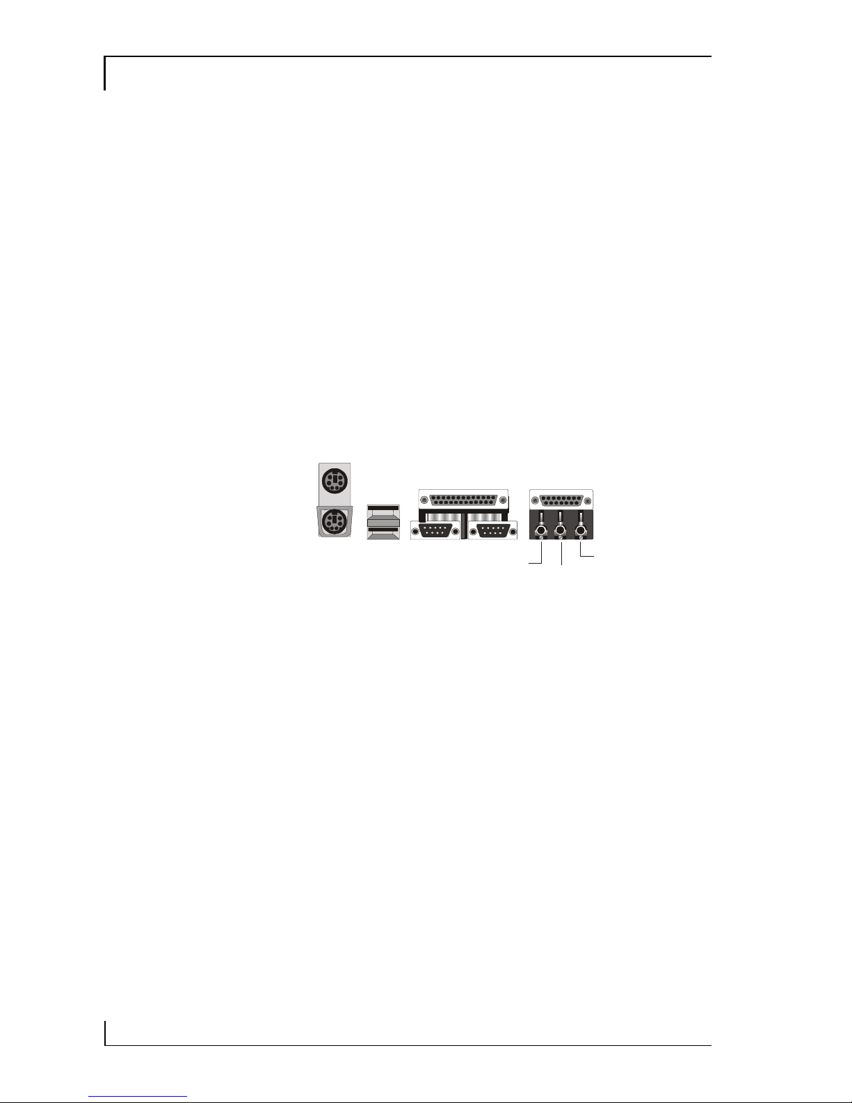
Integrated I/O
Both versions of the motherboard have a full set of
integrated I/O ports. The external ports mounted
on the board include PS/2 keyboard and mouse
ports, two USB ports, a parallel port, a serial port,
a VGA port, a game/MIDI port and three audio
jacks.
There are connectors on the motherboard for the
second serial port and an optional infrared port. A
port bracket for the second serial port comes with
the motherboard. The infrared port is an optional
purchase. If you install an infrared port, the sec-
ond serial port is disabled.
Onboard Peripheral Interfaces
Both versions of this motherboard support and
have connectors for two IDE channels and a flop-
py disk drive interface. The board supports two
floppy disk drives. The two IDE channels support
two devices each for a total of four devices. All
IDE data transfer modes are supported including
all PIO modes and UltraDMA33 and 66 modes
for a maximum data transfer rate of 66MB per
second. The motherboard comes with one floppy
and one IDE. The IDE cable supports all IDE
modes and devices including.
KB USB COM1 VGA
MS
Parallel port
Line out Line In
MIC
MIDI/Game port

Motherboard Features 1
5
System Memory
The motherboard has two sockets for 168-pin 3.3V
non-buffered SDRAM DIMM memory modules.
You can use PC100 or PC133 memory. PC66
memory is not supported. You can install any
combination of DIMMs from 16MB to 256MB
for a maximum system memory of 512MB.
Onboard 2D/3D Video Display
The Intel 810e chipset supports both video display
and audio onboard.
The onboard video display supports both 2D and
3D display graphics. Display drivers are supplied
on the Support Disk that comes with the mother-
board. The motherboard also has 4MB of display
cache memory mounted on the board to improve
display performance.
The integrated display feature is DDC2B compli-
ant and supports screen resolutions up to 1600 x
1200, 24-bit color and high refresh rates using a
230MHz DAC. The maximum display supported
is 1600 x 1200 resolution with 8-bit color at an
85Hz refresh rate.
The BIW2A-AT also supports TV-Out onboard.
TV-Out allows the use of a television set as the
display device instead of a conventional computer
monitor. The TV-Out feature includes an external
port bracket with RCA and S-Video ports for con-
necting a television set.
AT

1BIW2A User’s Manual
6
Onboard 32-bit Audio
The standard onboard audio supported by the
810e chipset comes with audio drivers that are
supplied on the Support Disk. The audio subsys-
tem uses the onboard Line-In, Mic and Line-Out
jacks to connect external devices and also uses any
of the onboard CD-ROM audio-in connectors to
process audio from a system CD-ROM drive.
The standard audio includes an AC’97
DAC/ADC built into the audio CODEC. This
reduces noise to improve audio quality and per-
formance for a signal-to-noise ratio of +90dB,
which greatly improves voice synthesis and recog-
nition.
The enhanced model of the BIW2A-AT replaces
the standard audio with an enhanced Creative
Labs 5880 audio chip and codec that use different
audio drivers which are also on the Support Disk.
Expansion Options
This motherboard has five 32-bit Revision 2.2 PCI
expansion slots for PCI expansion cards. All slots
are Bus Master capable. In addition, there is a slot
for an optional Modem Riser card that provides
an onboard telephony connection.
ACPI Ready
ACPI (Advanced Configuration and Power Inter-
face) support provides more energy saving func-
tions for operating systems that support ACPI
such as Windows 98. An ACPI-capable system
can use the ACPI OnNow feature to turn off sys-
tem peripherals and wake the system up from
Suspend mode via several means including point-
ing device movement and key commands.
AT

Motherboard Features 1
7
Programmable Firmware
The motherboard has a 4Mbit firmware hub that
includes the PC98-compliant Award PnP BIOS
and the CMOS Setup Utility which allows setting
of various system hardware parameters. The
CMOS Setup Utility has a new easy-to use inter-
face which provides more control over and protec-
tion of the motherboard.
Virus Protection
This motherboard comes with two forms of com-
puter virus protection. When enabled, the anti-
virus feature in the Award BIOS protects the pri-
mary hard disk drive’s boot sector and partition
table. The motherboard also comes with PC-cillin
98, anti-virus utility software for Microsoft Win-
dows 9x. The software is located on the Support
Disk that comes with the motherboard.
Options
As mentioned above, there are some optional fea-
tures available for these motherboards. The op-
tional features are of two types, factory-installed
and separately purchased.
Two factories installed options, Creative audio
and TV-Out are available on BIW2A-AT. You
must purchase the correct model to get them.
Both the BIW2A and BIW2A-AT support in-
stalling a Modem Riser card to install modem and
other telephony features. The Modem Riser card
is available separately. Ask your vendor for details.

1BIW2A User’s Manual
8
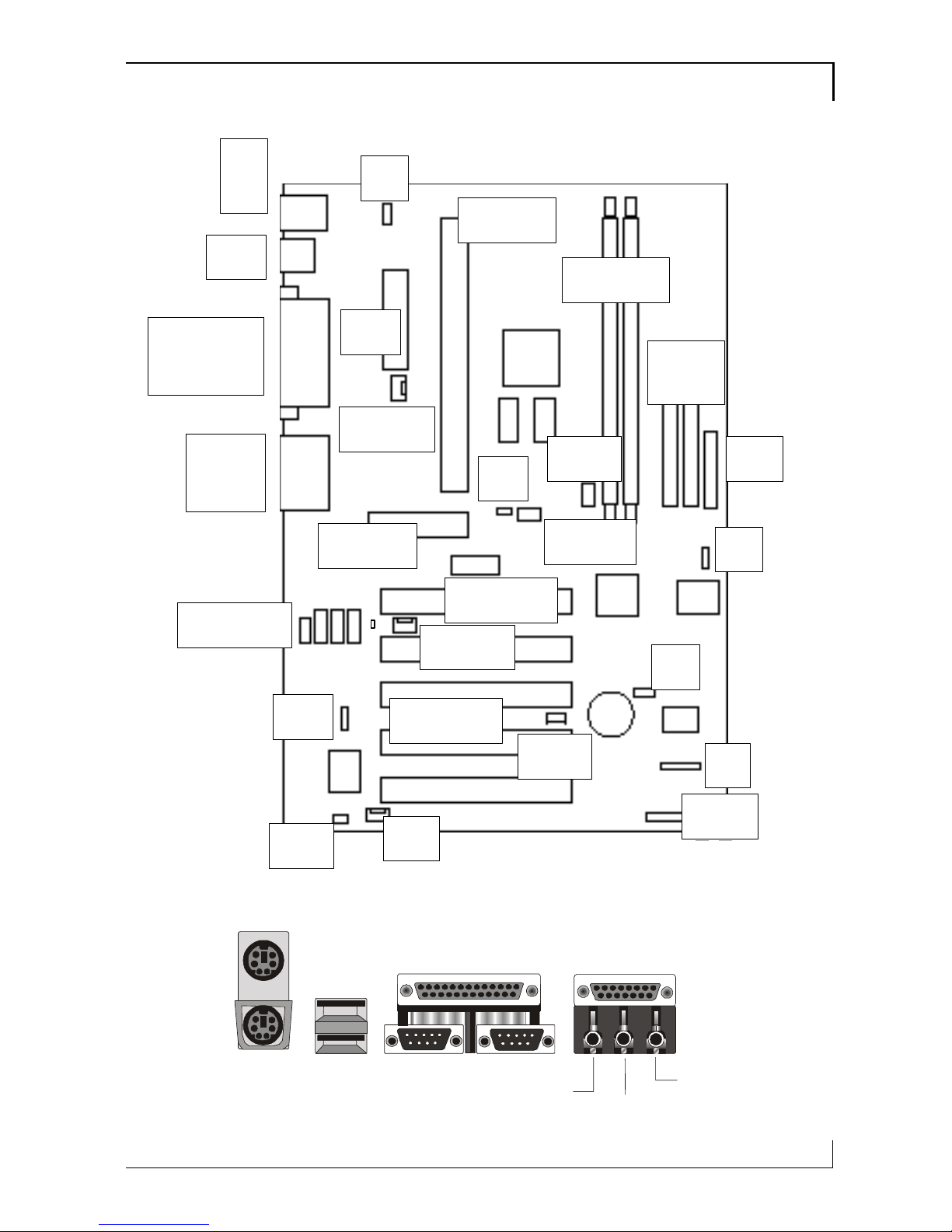
Layout & Port Positions
The figure at right shows the layout of the en-
hanced model of the BIW2A-AT motherboard
with the optional TV-Out components on the
board. The BIW2A does not have these compo-
nents. Otherwise, the are the same for the pur-
poses of this illustration.
Component Description
MR Riser Modem Riser slot
PCI 1,2,3,4,5 5 32-bit PCI expansion slots
WOL Connector for LAN Wake up
Slot 1 Slot 1 CPU at 233~733MHz
DIMM1,DIMM2 2 168-pin memory sockets
FDC Floppy disk drive connector
IDE1, IDE2 Primary & secondary IDE connectors
ATX Power ATX power supply connector
IrDA Optional infrared port connector
CPU FAN, SYS-
FAN, FAN CPU or System cooling fan power connectors
COM port 2nd serial port bracket connector
CD audio CD-ROM drive audio input connectors
Panel System housing front panel features connector
JP2 Keyboard/Mouse Power-on jumper
JP3 Clear CMOS memory jumper
JP4 Onboard AC97 audio jumper
JP5 BIOS Protect mode jumper
JP21 CPU & Bus external clock selection jumper
JP12* TV-Out jumper
JP17* Onboard Creative audio jumper
Motherboard Features 1
9
JP2
JP4
JP11
COM port
WOL
IR
SYSFAN
CD audio
MR riser
PCI Slots
Slot 1
ATX
DIMM1,2
JP8
FDC
IDE2
IDE1
Panel
JP3
JP13 FAN
TV-Out
CPUFAN
USB
MS
KB
Parallel
VGA COM
Game
Audio
KB USB COM1 VGA
MS
LPT
Line Out Line In
MIC
MIDI/Game port
JP5

1BIW2A User’s Manual
10

Configuration & Installation 2
11
Configuration & Installation
This chapter explains how to configure the moth-
erboard, install a CPU and system memory and
has basic information on installing the mother-
board in a system housing or “chassis”. We then
explain how to install the support software that
comes on the Support Disk. If the board is already
installed in a system, you may want to review this
chapter or you can skip it and go to the next chap-
ter which covers some post-installation topics.
Hardware Configuration
There are three steps to configure the mother-
board hardware before installing it in a system
housing: configuring the jumper switches, in-
stalling a CPU and installing system memory.
Configuring The Jumpers
This motherboard has five standard jumper
switches and the BIW2A-AT has two extras, one
for the TV-Out feature and one for the Creative
audio option. All the jumpers come preset to de-
fault settings. You will probably not need to
change any of the settings. Please note that once
the motherboard is installed, you should always
turn your computer off and disconnect the power
cord before changing any jumper settings. In all
cases, you should always take precautions against
static electric damage to sensitive components.
The default settings are listed in the following ta-
ble.
What’s In This
Chapter:
Hardware Con-
figuration
Installing the
Motherboard
Installing Support
Software

BIW2A User’s Manual
12
Jumper Setting Summary
JP2 Power On Feature
1-2 Enabled
2-3 Disabled
JP3 Clear CMOS
1-2 Normal
2-3 Clear CMOS
JP4 Onboard Audio
1-2 Disable
2-3 Enable
JP5 BIOS B.B. Protect
Short Jumper Unprotected
Open Jumper Protected
JP11 CPU & Bus Clock
Short 1-3, 2-4 Auto Detect
Short 3-5, 4-6 66 MHz
Short 3-5 100MHz
All Open 133MHz
JP8* TV System
Short Jumper NTSC
Open Jumper PAL
JP13* Creative Audio
Open Jumper Disable
Short Jumper Enable
Default settings
are in bold
*On BIW2A-AT
only
JP2
JP8
JP13
JP11
JP3
JP4
JP5

Configuration & Installation 2
13
Jumper Functions
This is sections explains the functions performed
by the jumper switches.
JP2: Power On Feature
This jumper sets support for the Power On feature
under the ACPI power saving specification. When
this feature is enabled, a PC98-compliant key-
board or a pointing device can turn on the system
in a number of ways. You can configure how the
feature operates in the Integrated Peripherals sec-
tion of the CMOS Setup Utility. See Chapter 3 for
more information on this. The default setting is
Enabled.
JP3: Clear CMOS
This jumper is a trouble shooting jumper that al-
lows you to clear the system configuration record
that is created by the Award BIOS CMOS Setup
Utility and stored in CMOS memory. You only do
this if the system has become unbootable due to
incorrect settings or a corrupted configuration re-
cord and you can’t access the CMOS Setup Utility.
Please refer to the section on Troubleshooting in
Chapter 5 for information on how to do this. The
default setting of this jumper is Normal.
JP4: Onboard Audio
This jumper enables or disables the onboard audio.
If you will use either the standard or enhanced
onboard audio, this must be set to Enabled. If you
do not want to use the onboard audio, set this
jumper to the Disabled setting. The default setting
is Enabled.
Note: If you will not use the onboard audio, don’t
install an audio driver from the Support Disk.
2
4
JP2
2
4
JP
4
2
JP4

BIW2A User’s Manual
14
JP5: BIOS Boot Block Protection
This jumper protects the BIOS Boot Block from
accidental damage. If there is a failure when in-
stalling new BIOS, the protected setting allows
you to boot from a bootable floppy disk with the
Flash utility and BIOS file on it and install new
BIOS. Note that when the jumper is set to the pro-
tected setting, the BIOS Boot Block is not updated
when installing new BIOS. This may cause a small
degree of malfunction once the new BIOS is in-
stalled. We do not recommend changing the de-
fault. The default setting is Unprotected.
JP11: CPU & External Clock Frequency
This jumper sets the external clock frequency used
to set the CPU’s operating speed. The Auto de-
fault setting will detect the necessary speed for the
installed CPU. All Celeron CPUs are specified to
use the 66MHz setting. You can also manually the
clock speed to 100MHz or 133MHz. The default
setting is Auto.
JP8: TV-Out Mode
This jumper is only present on the BIW2A-AT. It
sets the TV system mode used by the TV-Out fea-
ture. The jumper must be set to use the mode used
by televisions in your country, either NTSC or
PAL. The default setting is NTSC.
JP13: Onboard Creative Audio
This jumper is only present on the BIW2A-AT.
The jumper enables and disables onboard audio
for the Creative audio chip. The default setting is
Short, which enables the Creative chip.
JP1
JP8
JP5
32
JP11
76
54

Configuration & Installation 2
15
Installing A CPU
This motherboard has an Intel Slot 1 CPU socket.
If you purchased a CPU packaged by Intel, follow
the installation instructions that come with it. In
any case, please review the following generic in-
structions. You must install the CPU Retention
Module that comes with the motherboard first.
Make sure you take precautions against static elec-
tric damage.
1. Install the CPU Retention Module.
Place the module over the Slot 1 socket and
press it into the mounting holes. It will only fit
in one orientation.
Insert the module retaining pins into the four
corner receptacles on the module and press
them into the holes until they are secured.
Please Note:
The pictures in
this section are
generic and are
not of the moth-
erboard this
manual is about.

BIW2A User’s Manual
16
2. Insert the CPU in the Slot 1.
Note that the Slot 1 socket has two sections of
different lengths. Orient the CPU to the socket.
Slide the CPU into the Retention Module
guide rails and press the CPU into the socket
3. Install the retaining caps.
Press a retaining cap onto the top of each Re-
tention Module guide rail to secure the CPU
in the Slot 1 socket. The caps will snap in
place.
Table of contents
Other Procomp Motherboard manuals


