Procomp B687 User manual

Contents
i
CONTENTS
CH1. MOTHEROARD FEATURE .............................................................1
!SPECIFICATIONS..........................................................................1
!POWER OFF CONTROL SOFTWARE .........................................3
!PACKAGING CHECK LIST ..........................................................3
CH2. SETUP GUIDE ....................................................................................4
!MAINBOARD LAYOUT DRAWING ...........................................4
!JUMPER & CONNECTOR SETTING ...........................................5
CONNECTOR SETTING ...............................................................5
J7 OTHER JUMPER SETTING.....................................................8
CPU TYPE SELECT ......................................................................
FAN CONNECTOR .....................................................................12
!HOW TO INSTALL THE CPU.....................................................15
!MEMORY INSTALLATION........................................................1
CH3. AWARD BIOS SETUP......................................................................22
!THE MAIN MENU .......................................................................24
!STANDARD CMOS SETUP ........................................................26
!BIOS FEATURES SETUP ............................................................28
!CHIPSET FEATURES SETUP .....................................................32
!POWER MANAGEMENT............................................................35
!PNP / PCI CONFIGURATION SETUP ........................................3
!INTEGRATED PERIPHERALS ...................................................41
!LOAD BIOS DEFAULT ...............................................................43
!LOAD SETUP DEFAULT ............................................................43
!SUPERVISOR / USER PASSWORD SETTING..........................43
!IDE HDD AUTO DETECTION....................................................44
REMARK
INTEL® is a registered trademark of Intel Corporation.
All other brands and product names are trademarks registered trademarks of their
respective companies.

B687
1
SPECIFICATIONS
System Chipset Intel®
44 BX chip set , ALi 513X
CPU Bus Speed Pentium®
҈/III, 66 and 1 MHz CPU
CPU Clock 2 MHz ~ 55 MHz
Memo y Subsystem Expandable to 256MB(2 banks) with 168-Pin
SDRAM(DIMM) Socket X2
AGP Slot AGP Interface Specification Rev 1. Compliant
Integ ated I / O
Two high speed 1655 compatible serial ports,
one Multi-Mode Parallel Port fixed
SPP/EPP/ECP standard
Two PCI Bus master Ultra DMA/33 IDE port (up
to 4 IDE Devices)
Support two 36 KB / 72 KB / 1.2MB / 1.44MB /
2.88MB / floppy disk driver
Support LS12 drives & ZIP 1 Drives
One PS/2 Mouse port
Support two USB ports
Support IrDA TX / RX header
Chapter 1
Motherboard Feature Introduction

B687
2
BIOS
1MB Flash ROM
Award AGP BIOS with green, plug and play,
ACPI,
DMI feature support
Support secondary device boot
Expansion slot
Three 32-bit PCI Slots & Two 16-bit ISA Slots
Support 3.3/5V PCI 2.1 bus Interface
EXTRA Function
Suspend LED on/off
Win95 soft power off
External SMI
Wake up by ring
Wake on Lan
Powe Supply Support AT & ATX power
Dimension Baby AT size (22 mm x 22 mm), 4-layer PCB

B687
3
POWER OFF CONTROL SOFTWARE
The motherboard design supports software power off Control feature
through the SMM code in the BIOS under Win 5 operating system
environment. This is INTEL Baby AT form factor feature and you should use
ATX/AT power supply.
First, you should connect the power switch cable (provided by the
ATX/AT case Supplier) to the connector [ PB_BT ] on the motherboard. In
the BIOS screen of “POWER MANAGEMENT SETUP”, choose “User
Defined”(or min power saving or Max power saving) in “POWER
MANAGEMENT” and choose “Yes” in “PM Control by APM”.
In Windows 5 the “ SHUT DOWN “ option , the computer’ s Power will
switch off automatically and put the PC in a suspend mode. This will be
indicated by a bunking power light. To restart the system , simply press the
Power Button.
PACKAGING CHECK LIST
The motherboard comes securely packed in a gift box and shipping carton.
If any of the above items are missing or damaged , please contact your
supplier.
The motherboard contains:
Q’ TY Description
1 Motherboard : with Intel ZX chipset
1
Driver
: CD-Title w/Installation label
• PC-Cillin Software
• Motherboard Bus master Driver
1 Cable : FDD. IDE. COM1/2. PS2. LPT
Connector
1 Manual : User’ s manual
B687
4
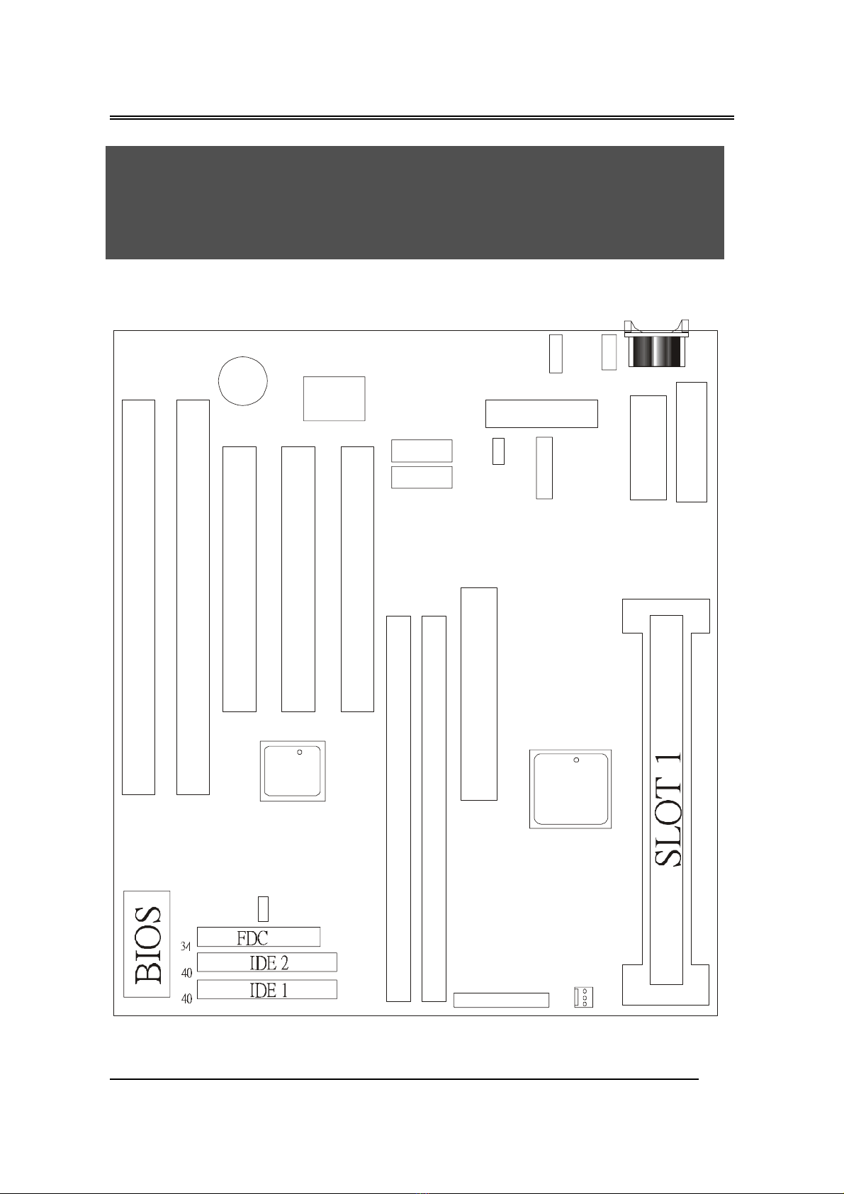
Mothe boa d Layout D awing
Chapter 2
Setup Guide
˜˸˿
ˇˇ˃˕˫
˔˚ˣʳ˸
˥
˔˚ˣʳ˦˟ˢ˧
˗˜ˠˠʳ˄
˗˜ˠˠʳ˅ ˣ˖˜ʳ˄
ˣ˖˜ʳ˅
ˣ˖˜ʳˆ
ˆ˩
˕˴˸
˜˦˔ʳ˄
˜˦˔ʳ˅
˟ˣ˧ʳ˄ʳ
˔˧˫ʳˣˢ˪˘˥ʳ
˖˸˶
˔˧ʳˣˢ˪˘˥
˖˸˶
˖ˢˠʳ˄
˖ˢˠʳ˅
˝ˣ˅
˝ˣˆ
˝ˣˈ
˝ˣˉ
˨˦˕˄
˝ʳ˅
˔˟˼
˜˂ˢ
˜˸˿
ˇˇ˃˕˫
ˣ˖˜ʳ˸
˥
˖ˣ˨ʳ˙˴
ʳʳʳʳʳ˝ˣˌ
˞˕ʳ˖˸˶
˄
˄
˄
˝˪ˢ˟˄
˝ˣ˄
˝ˣˊ
˝ˊ
˝ˣˇ
˝ˆ
˝ˣˋ

B687
5
Jumpe & Connecto Setting
CONNECTOR SETTING
J1- Keyboa d Connecto
Pin Desc iption
1 Keyboard Clock
2 Keyboard Data
3 NC
4 GND
5 +5V
J2 - Mini PS/2 Mouse Connecto
Pin Desc iption
1 Mouse Data
2 N.C.
3 Ground
4 +5V
5 Mouse Clock
J3 - ATX Powe Supply Connecto
Pin Desc iption
1,2,11 + 3.3 V
3,5,7,13,15,16,17 Ground
4,6,19,2 + 5 V
8 POWER GOOD
9 5VSB
1 +12 V
12 -12 V
14 PS-ON

B687
6
18 - 5 V
JP4 – AT Powe Supply Connecto
Pin Desc iption Pin Desc iption
1 Power Good 7Ground
2 +5V DC 8Ground
3 +12V DC 9-5V DC
4 -12V DC 1 +5V DC
5 Ground 11 +5V DC
6 Ground 12 +5V DC
LPT1 - P inte Connecto
Pin Signal Name Pin Signal Name
1 Strobe- 14 AFD
2 Data Bit 15 Error
3 Data Bit 1 16 INIT
4 Data Bit 2 17 SLCTIN
5 Data Bit 3 18 GND
6 Data Bit 4 19 GND
7 Data Bit 5 2 GND
8 Data Bit 6 21 GND
9 Data Bit 7 22 GND
1 ACK 23 GND
11 Busy 24 GND
12 PE 25 GND
13 SLCT 26 GND

B687
7
COM1,COM2 –Se ial Connecto s
Pin Signal Name Pin Signal Name
1 DCD 6 DSR
2 SIN 7 RTS
3 SOUT 8 CTS
4 DTR 9 RI
5 GND 1 NC
USB1 - Unive sal Se ial Bus (USB) Connecto s
USB1 Pin Signal Name USB2 Pin Signal Name
1 USB VCC 1 USB VCC 1
2 USB Data - 2 USB Data -
3 USB Data + 3 USB Data +
4 USB GND 4 USB GND 1
5 GND 5 GND
5135SIR - Inf a ed Connecto : IR
Pin Signal Name
1 VCC
2 NC
3 IRRX
4 GND
5 IRTX
B687
8
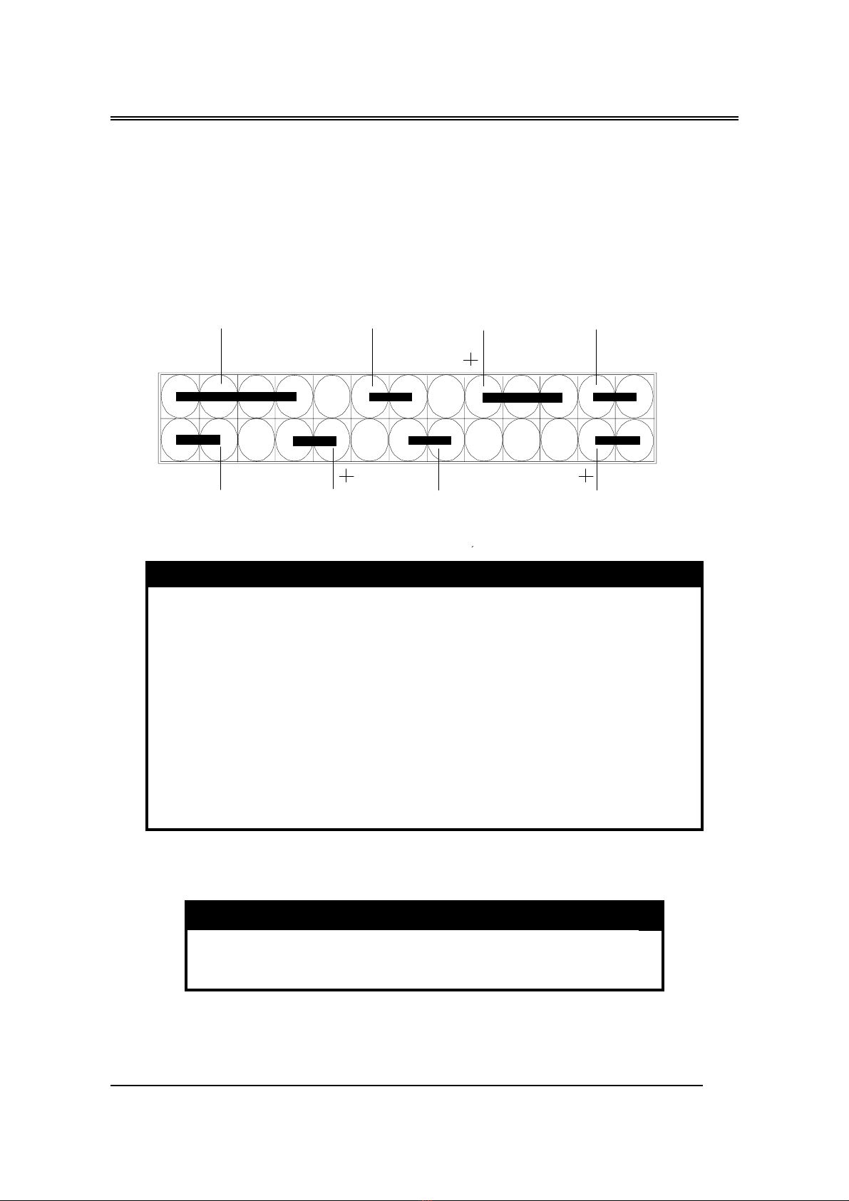
J7 – OTHER JUMPER SETTING
Pin Name Desc iption
1-3 SMI Suspend mode
7-9 SUS _ LED Suspend mode LED
13-15 PB _ BT Power buttem
23-25 HD – LED Hard Disk LED
2-8 SPEAKER Speaker
12-14 RST Reset buttom
18-22 PWR - LED Power LED
24-26 KEYLOCK Key Lock
JP8 – CMOS Clea
JP8 Desc iption
1-2 Normal (default)
2-3 Clear CMOS
P2 P26
P1 P25
SPEAKER RST PWR_LED
SMI HD_LED
PB_BT
SUS_LED
KEYLOCK

B687
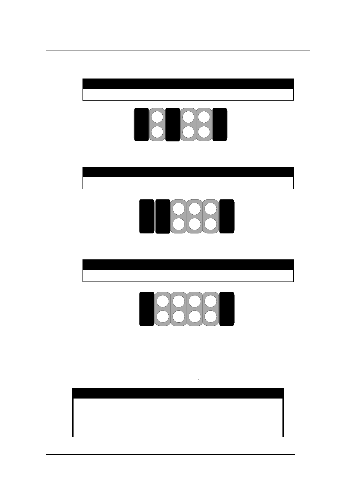
CPU TYPE Select
CPU Bus Speed - 66MHz pa t :
1. 233MHz
JP1 JP2 JP3 JP5 JP6 JP7
Sho t Open Open Sho t Sho t Sho t
2. 266MHz
JP1 JP2 JP3 JP5 JP6 JP7
Sho t Sho t Sho t Open Sho t Sho t
4. 300MHz
JP1 JP2 JP3 JP5 JP6 JP7
Sho t Open Sho t Open Sho t Sho t
JP1 JP2 JP3 JP6JP5
JP7
JP1 JP2 JP3 JP6JP5
JP7
JP1 JP2 JP3 JP6JP5 JP7

B687
10
5. 333MHz
JP1 JP2 JP3 JP5 JP6 JP7
Sho t Sho t Open Open Sho t Sho t
6. 366MHz
JP1 JP2 JP3 JP5 JP6 JP7
Sho t Open Open Open Sho t Sho t
7. 400MHz
JP1 JP2 JP3 JP5 JP6 JP7
Open Sho t Sho t Sho t Sho t Sho t
8. 433MHz
JP1 JP2 JP3 JP6JP5 JP7
˝ˣ˄ ˝ˣ˅ ˝ˣˆ ˝ˣˉ˝ˣˈ
˝ˣˊ
˝ˣ˄ ˝ˣ˅ ˝ˣˆ
˝ˣˉ
˝ˣˈ ˝ˣˊ

B687
11
JP1 JP2 JP3 JP5 JP6 JP7
Open Open Sho t Sho t Sho t Sho t
9. 466MHz
JP1 JP2 JP3 JP5 JP6 JP7
Open Sho t Open Sho t Sho t Sho t
10. 500MHz
JP1 JP2 JP3 JP5 JP6 JP7
Open Open Open Sho t Sho t Sho t
11. 533MHz
JP1 JP2 JP3 JP5 JP6 JP7
Open Sho t Sho t Open Sho t Sho t
˝ˣ˄ ˝ˣ˅ ˝ˣˆ
˝ˣˉ
˝ˣˈ ˝ˣˊ
˝ˣ˄ ˝ˣ˅ ˝ˣˆ
˝ˣˉ
˝ˣˈ ˝ˣˊ
˝ˣ˄ ˝ˣ˅ ˝ˣˆ
˝ˣˉ
˝ˣˈ ˝ˣˊ
˝ˣ˄ ˝ˣ˅ ˝ˣˆ ˝ˣˉ˝ˣˈ ˝ˣˊ

B687
12
CPU Bus Speed - 100MHz pa t :
1. 300MHz
JP1 JP2 JP3 JP5 JP6 JP7
Sho t Sho t Open Sho t Open Sho t
2. 350MHz
JP1 JP2 JP3 JP5 JP6 JP7
Sho t Open Open Sho t Open Sho t
3. 400MHz
JP1 JP2 JP3 JP5 JP6 JP7
Sho t Sho t Sho t Open Open Sho t
JP1 JP2 JP3 JP6JP5 JP7
JP1 JP2 JP3 JP6JP5 JP7
JP1 JP2 JP3 JP6JP5 JP7
B687
13
4. 450MHz
JP1 JP2 JP3 JP5 JP6 JP7
Sho t Open Sho t Open Open Sho t
5. 500MHz
JP1 JP2 JP3 JP5 JP6 JP7
Sho t Sho t Open Open Open Sho t
6. 550MHz
JP1 JP2 JP3 JP5 JP6 JP7
Sho t Open Open Open Open Sho t
CPU TYPE SELECTION LIST
JP1~JP5 (Fo RATIO select)
RATIO JP1 JP2 JP3 JP5
3.0 Short Short Open Short
3.5 Short Open Open Short
4.0 Short Short Short Open
4.5 Short Open Short Open
JP1 JP2 JP3 JP6JP5 JP7
JP1 JP2 JP3 JP6JP5 JP7
JP1 JP2 JP3 JP6JP5 JP7

B687
14
5.0 Short Short Open Open
5.5 Short Open Open Open
JP6 (Fo BUS clock)
CLOCK JP6
66 MHz Short
100 MHz Open
JP7 (CPU BUS Clock manual / Auto detect)
CLOCK JP7
Default (Auto Detect) Short
Force BUS CLOCK up to 100 MHz Open
FAN CONNECTOR
JP9: This fan is used in CPU COOL FAN.
Sho t Open
JP
GND +12V
12
3
NC

B687
15
How to install the CPU
Prepare the motherboard by installing the supplied Slot 1 CPU, then
install the CPU according to the instructions supplied. Complete the
processor installation by installing the supplied heat-sink support, and
connecting the heat sink power cable to the motherboard connector.
Refe ential Steps of installing the Slot 1 CPU
This part is only for CPU installation. Regarding to the heat-sink part, please
refer the instructions supplied.
B687
16
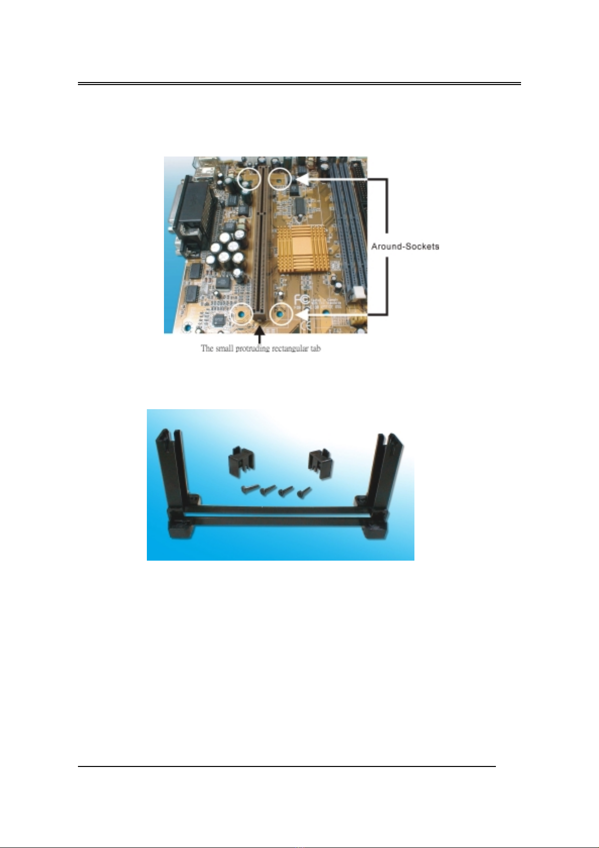
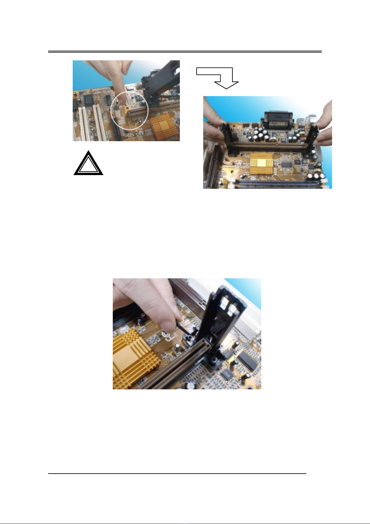
1. Inspect the area around Slot1, verify the position of four around-
sockets, and then locate the small protruding rectangular tab on the side
of Slot1 (see diagram).
2. Examine the CPU Retention and attachments. There are three sets of
attachments: 1. The stand itself. 2. The CPU locking caps (two). 3.
The plastic screws (four).
3. Once the above two steps have been completed, slot the CPU Retention
into Slot1. Pull up the CPU stays on both side of the CPU Retention so
they are horizontal, at an angle of 0°. Then the side of the CPU
Retention with no mark on it and the side of Slot1 with the small
rectangular tab should be on the same side.
B687
17
4. Ensure that the CPU Retention has been slotted all the way in, then
screw the four plastic screws into the sockets on each side of Slot1 to
make sure that the CPU Retention is fixed firmly in position.
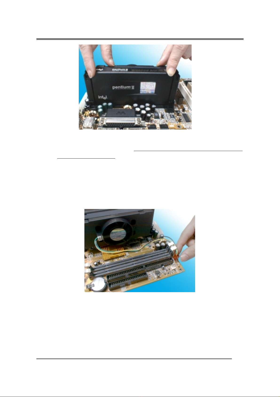
5. Slide the CPU slowly into Slot1 along the two sides of the CPU
Retention.
! The CPU Retention has
to go in a particular direction.
Make sure that it is the right wa
y
round before slotting it in. Do no
t
force it in, otherwise you ma
y
damage the motherboard and
CPU Retention.
B687
18
Note: Some Slot 1 processors with different packing maybe need the caps to
let them be fixed. So if it need the caps during installing Slot 1 CPU,
please follow this step: “ Fix the CPU locking caps onto the two
ends of the CPU stays ”.
6. Connect the CPU Fan head to the CPU Fan connector on the
motherboard, and make sure that the CPU has been fixed firmly onto
the motherboard. You have now completed assembly.
SLOT 1 CPU Disassembly/Replacement P ocedu es
1. Move the protruding part on top of the CPU locking caps gently
outwards, so that the locking caps come off.

B687
1
2. Pull the CPU Fan connector off the motherboard, and then gently pull
the CPU out from Slot1.
3. If you need to install another CPU, follow the instructions for Slot1
CPU installation given above.
CPU & Powe Supply Fan Connecto s (3-pin FanPWR)
These connector support cooling fans of 500mAMP (6WATT) or less. Orien-
tate the fans so that the heat sink fins allow airflow to go across the onboard
heat sink(s) instead of expansion slots. Depending on the fan manufacturer,
the wiring and plug may be different. The red wire should be positive, while
the black should be ground. Connect the fan’ s plug to the board taking into
consideration the polarity of this connector.
The CPU and motherboard will overheat if there is no airflow
across the CPU and onboard heatsinks. Damage may occur to the
motherboard and the CPU fan if these pins are incorrectly used.
MEMORY INSTALLATION
No jumper setting is necessary for DRAM setting; BIOS will check
DRAM type and size automatically. This motherboard contains 2 by 168-pin
The “Rotation” signal is to be used only by a specially designed fan with
rotation signal.
!
Table of contents
Other Procomp Motherboard manuals


