Procomp b598 User manual

Contents
i
CONTENTS
ch1. Motherboard Feature............................................................................1
!SPECIFICATIONS..............................................................................1
!WHAT IS B598 MOTHERBOARD....................................................3
!PACKAGING CHECK LIST ..............................................................3
ch2. Setup Guide ............................................................................................4
!MAINBOARD LAYOUT DRAWING................................................4
!JUMPER CONNECTOR SETTING ...............................................5
CONNECTOR SETTING ..........................................................................5
JP1 OTHER JUMPER SETTING ................................................................7
CPU TYPE SELECT ................................................................................8
FAN CONNECTOR...............................................................................10
!MEMORY INSTALLATION............................................................11
ch3. Award BIOS Setup ..............................................................................12
!THE MAIN MENU ...........................................................................14
!STANDARD CMOS SETUP.............................................................16
!BIOS FEATURES SETUP ................................................................17
!CHIPSET FEATURES SETUP .........................................................23
!POWER MANAGEMENT................................................................24
!PNP / PCI CONFIGURATION SETUP ............................................26
!INTEGRATED PERIPHERALS .......................................................27
!LOAD BIOS DEFAULT ...................................................................28
!LOAD SETUP DEFAULT ................................................................28
!SUPERVISOR / USER PASSWORD SETTING..............................28
!IDE HDD AUTO DETECTION........................................................29
REMARK
INTEL®
is a registered trademark of Intel Corporation.
All other brands and product names are trademarks registered trademarks of
their respective companies.

B598
1
SPECIFICATIONS
System Chipset Cyrix Cx5530, AT ompatibility logi
CPU Clock Cyrix Media Gxm Pro essor speed up to 300 MHz
16KByte unified L1 a he
Clock Generator Mi roClo k MK1491-06, support power down mode
and PCI lo k stop mode
Memory Subsystem 2 x 168 pin DIMM modules support SDRAM, up to
256MB
Inte rated I / O NS97317 Super I/O Chipset
Built-in RTC(Real-Time Clo k) and Keyboard
Controller
BIOS 2M bits Flash ROM
Award PCI BIOS with Green ,Plug & Play Feature
Expansion slot 3 x 32-bit PCI slots & 2 x 16-bit ISA slots
2 x Bus Master IDE port support 4 IDE devi es
1 x Floppy port support 2 floppy devi es
2 x 168 pin DIMM modules So kets
On-Board
VGA and Audio
Cyrix XpressGraphi Video using VSA Te hnology
Video ontroller with 2D graphi s a eleration for
BitBLTs.
MPEG 1 hardware a elerator
Display Resolution
640 x 480 256/16-bit High Color 60Hz
800 x 600 256/16-bit High Color 60Hz
1024 x 768 256/16-bit High Color 60Hz
1280 x 1024 256 Color 60Hz
Cyrix XpressAudio, Sound Blaster ompatible
Virtual Audio, 16 bit industry standard
AC97 ompliant Audio Code
Stereo Amplifier (Output power 250mW for ea h
hannel)
Chapter 1
Motherboard Feature

B598
2
EXTRA Function PC98 ompliant
Power Management Supporting
Compatible with PnP requirement
Compliant with ACPI spe Rev 1.0
External Connectors 1 x IrDA Port (IrDA 1.0-SIR/ on UART 2)
1 x Parallel Port Conne t Support ECP/EPP/SPP
mode
2 x PS/2 Port for PS/2 Keyboard and Mouse
2 x USB Ports with Open HCI ompliant
2 x High Speed Serial Port
(COM2 have to onne t through a loop-ba k able)
1 x Line-Out, 1 x Line-In, 1x Mi rophone onne tor
1 x VGA onne tor
1 x Game Port
Dimension Mi ro ATX size 244mm(L) x 244mm(w) x 4 layers
PCB

B598
3
What is B598 Motherboard?
With the availability of new IC packing technology, Cyrix Cx5530
which provides highly efficient bus transaction, highly concurrent
architecture, USB, PS/2 KBC, 2 channel dedicated Ultra-33 IDE Master, with
the best power management, ACPI and Super I/O.
The Cyrix Cx5530 consists only one chip which give the 586 class
system a complete solution with the most up-to-date features and architecture
for the new multimedia/multithreading OS.
Cyrix Cx5530 provides a highly integrated system solution and a most
up-to-date architecture, flexible 32/64-bit memory bus and concurrent multi-
bus with highly efficient, deep FIFO between the buses, such as the
HOST/PCI/ISA/IDE bus.
B598 only supports Cyrix Media GXm CPUs but it has perfect performance
when you use the Cyrix Media GXm CPU.
PACKAGING CHECK LIST
The motherboard comes securely packed in a durable box and shipping
carton. If any of the above items are missing or damaged , please contact your
supplier.
The motherboard contains:
Q’ TY Description
1 motherboard : B598
1 Driver : Driver for Audio Video
1 Cable : Enhanced IDE connector
1 Cable : F.D.D connector
1 Manual : User’ s manual
1 Cable : COM2 Cable

B598
4
B598 Motherboard Layout Drawin
Chapter 2
SETUP GUI E
USB 1 / 2
T: LPT1
B:COM1
VGA Port
T: Mouse
B: K/B
T: Game Port
B: Audio Port
So ke t 7
VGA BIOS
PC I
ISA
PC I
PC I
ISA
IDE 1
IDE 2
Floppy
CX5530
Battery
DIMM
DIMM
ATX Power
J1
JP2_RV
JFP1
JBAT
JMSPK
JCD1
JWOL
JCFAN2
JCFAN1
JP1
JCOM2
JCLK
JWOM1
JBFA
Connector Front View
KB USB COM1 VGA
MS
Parallel
Audio Out
Audio In
MIC
MIDI/Game port

B598
5
JUMPER & CONNECTOR SETTING
Connector Setting
JBAT - CMOS RAM operation mode
Shorted Function Remark
1-2 Normal operating
Default setting
2-3 Clear CMOS RAM Removed VCC5VSB
J1 - External speaker for PC-BEEP
Pin Function Remark
1-2 On board beeper Default
Remove short- ap
insert speaker onne tor
External speaker
JCD1 - Audio CD output connector
Pin Function Remark
1 Channel Right
2 CD Ground
3 Channel Left
4 CD Ground
JCOM2 - COM2
UART2 is shared by COM2, MIDI and SIR. To select COM2 item in
BIOS set-up menu while system boot-up
Pin Si nal name Pin Si nal name
1DCD 2RXD
3TXD 4DTR
5GND 6DSR
7RTS 8CTS
9 RI 10 NC

B598
6
JFP1 - MicroATX front end connector
Pin Si nal name Pin Si nal name
1HDD LED Anode (+) 2PWR_SUSP LED Anode (+)
3HDD LED Cathode (-) 4PRW_SUSP LED Cathode (-)
5Reset swit h (GND) 6PWR_ON swit h
7Reset swit h 8PWR_ON swit h (GND)
9+5V 10 Suspend swit h
11 IRRX 12 Suspend swit h (GND)
13 GND 14 KEY
15 IRTX 16 +5V
17 Reserved 18 Reserved
JWOL - WOL connector for Wake-On-LAN
Pin Si nal name Remark
1VCC5VSB
2GND
3PMEX
JWOM - Wake on MODEM card
Pin Si nal name Remark
1Modem ard ring-in Photo oupler type
2GND
JMSPK - Modem card speaker connector
Pin Si nal name Remark
1Mi rophone input (MICIN)
2GND
3GND
4Modem speaker (MSPK)

B598
7
JP2_RV - Keyboard lock connector
Pin Si nal name Remark
1NC
2NC
3GND
4Key lo k (KBDINHX)
5GND
JFP1 – OTHER JUMPER SETTING
P2
P17 P1
P18
IRTX Reset HDD_LED
PWR_SUSP LED
PWR_ON
Suspend
JP2_RV
P1
P1
P5
P5
JSIR

B598
8
Pin Name Description
1 - 3 HDD_LED HDD LED
5 - 7 Reset Reset switch
9 - 15 IRTX IRTX
2 - 4 PWR_SUSP LED Power Suspend LED
6 - 8 PWR_ON Power Button
10 - 12 Suspend Suspend switch
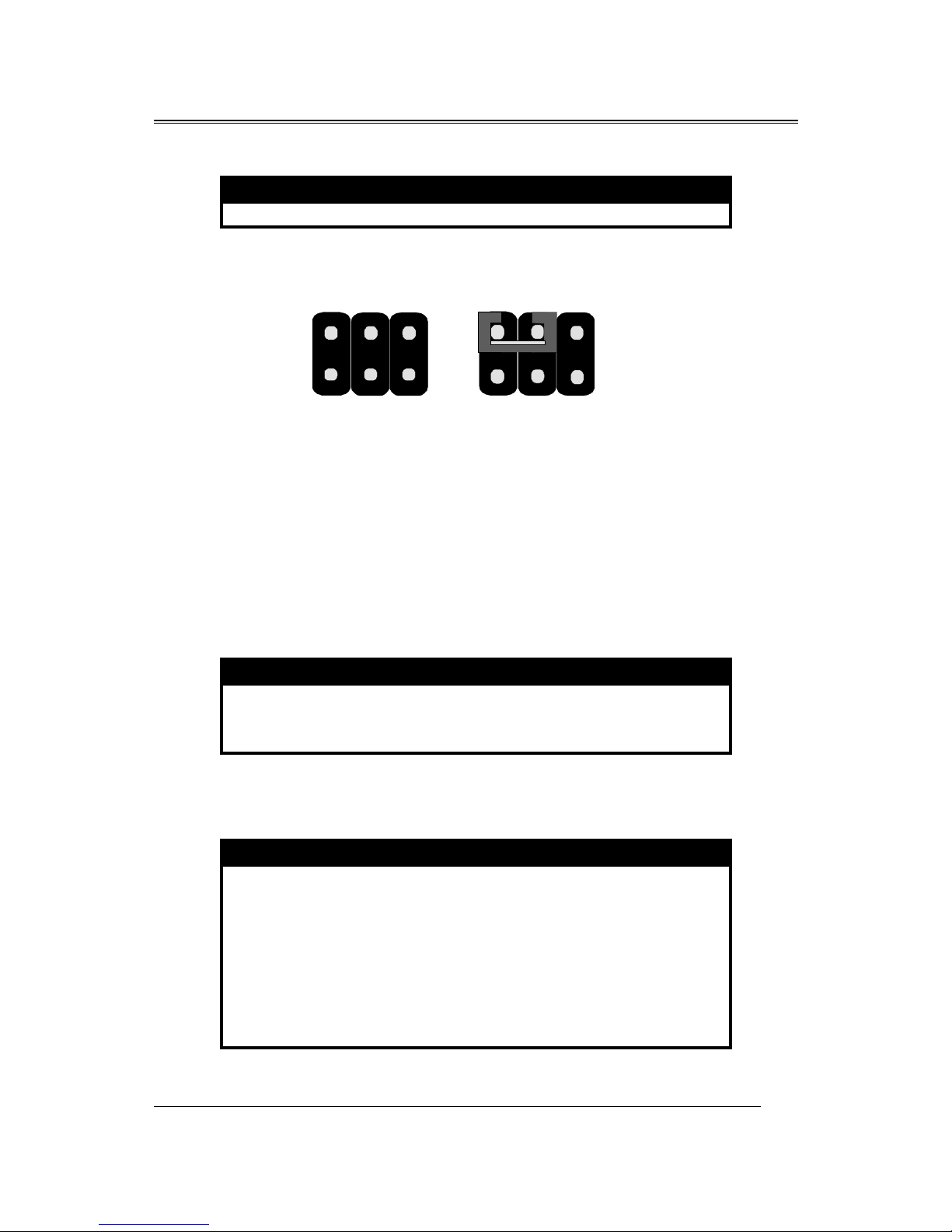
CPU TYPE Select
This motherboard is only designed for Cyrix CPU, and you will get high
performance in it!
1. Gxm 200MHz
CPU speed JCLK JBFA
Gxm 200MHz 2-4 3-4
Gxm 233MHz
CPU speed JCLK JBFA
Gxm 233MHz 2-4 5-6
1
2
35
46
JCLK
1
2
35
46
JBFA
1
2
35
46
JCLK
1
2
35
46
JBFA
B598
9
2. Gxm 266MHz
CPU speed JCLK JBFA
Gxm 266MHz 2-4 None
CPU TYPE SELECT LIST
Combination of JCLK and JBFA for Cyrix Mwdia GX CPU
speed settin
CPU speed JCLK JBFA
Gxm 200MHz 2-4 3-4
Gxm 233MHz 2-4 5-6
Gxm 266MHz 2-4 None
JBFA – Gxm CPU clock-multiple mode selection
Shorted Function Remark
1-2, 3-4, 5-6 4x Test Only
1-2 5x
3-4 6x
5-6 7x
None 8x
1-2, 5-6 9x
1-2, 3-4 10x
3-4, 5-6 Reserved
1
2
35
46
JCLK
1
2
35
46
JBFA

B598
10
JCLK – Bus frequency selection
Shorted Function Remark
1-3, 2-4 Reserved
1-3, 4-6 Reserved
2-4 33MHz
4-6 30MHz
3-5, 2-4 Reserved
3-5, 4-6 Tristate all lo ks
JP1 – Gxm CPU V-core volta e selection
Shorted Function Remark
None Shutdown
1-2 2.1 V
3-4 2.3 V
1-2, 3-4 2.3 V
5-6 2.4 V
1-2, 5-6 2.5 V
3-4, 5-6 2.6 V
1-2, 3-4, 5-6 2.7 V
7-8 2.8 V
1-2, 7-8 2.9 V Default setting
3-4, 7-8 3.0 V
1-2, 3-4, 7-8 3.1 V
5-6, 7-8 3.2 V
1-2, 5-6, 7-8 3.3 V
3-4, 5-6, 7-8 3.4 V
1-2, 3-4, 5-6, 7-8 3.5 V
FAN CONNECTOR
JCFAN1,JCFAN2 – CPU fan connector
JCFAN1:
Pin Function Remark
2 Fan positive No key prote tion
1,3 Fan negative

B598
11
JCFAN2:
Pin Function Remark
1,4 Fan positive With holder
2,3 Fan negative
MEMORY INSTALLATION
No jumper setting is necessary for DRAM setting, BIOS will check DRAM
type and size automatically. B598 motherboard contains 2 by 168-pin DIMM
sockets(DIMM1,DIMM2). B598 motherboard has table-free ( or auto-bank )
feature and user can install DIMM into any bank. The Two DIMMs Sockets for
system memory expansion from 8MB to 256 MB. Each bank provides 64-bit
wide data path.
NOTE: Samples of System Memory Combinations Options
DIMM1 DIMM2 TOTAL
8MB --- 8MBytes
--- 8MB 8MBytes
8MB 8MB 16MBytes
16MB --- 16MBytes
--- 16MB 16MBytes
16MB 8MB 24MBytes
8MB 16MB 24MBytes
16MB 16MB 32MBytes
--- 32MB 32MBytes
32MB --- 32MBytes
32MB 32MB 64MBytes
64MB --- 64MBytes
64MB 64MB 128MBytes
: : :
: : :
128MB 128MB 256MBytes

B598
12
Award BIOS ROM has a built-in Setup program that allows users to
modify the basic system configuration. This type information is stored in
battery-backed RAM so that it retains the Setup information when the power is
turned off.
ENTERING SETUP
Power on the computer and press <Del> immediately will allow you to
enter Setup. The other way to enter Setup is to power on the computer , when
the below message appears briefly at the bottom of the screen during the POST
(Power On Self Test), press <Del> key or simultaneously press <Ctrl>, <Alt>,
and <Esc> keys.
TO ENTER SETUP BEFORE BOOT PRESS CTRL-ALT-
ESC OR DEL KEY
If the message disappears before you respond and you still wish to enter
Setup, restart the system to try again by turning it OFF then ON or pressing the
"RESET" button on the system case. You may also restart by simultaneously
press <Ctrl>, <Alt> and <Del> keys. If you do not press the keys at the correct
time and the system does not boot , an error message will be displayed and you
will again be asked to,
PRESS F1 TO CONTINUE, CTRL-ALT-ESC OR DEL TO
ENTER SETUP
Control Keys
Up Arrow Move to previous item
Down Arrow Move to next item
Left Arrow Move to the item in the left hand
Right Arrow Move to the item in the right hand
Esc Key Main Menu Quit and not to save changes to
CMOS
Chapter 3
AWAR BIOS SETUP

B598
13
Status Page setup menu and Option Page
Setup Menu Exit current page and return to
Main Menu
PgUp Key Increase the numeric value or make changes
PgDn Key Decrease the numeric value or make changes
F1 Key General help, only for Status Page Setup
Menu and Option Setup
Menu
F2 Key Change color from total 16 colors
F3 Key Calendar, only for Status Page Setup Menu
F4 Key Reserved
F5 Key Restore the previous CMOS value from
BIOS, only for Option
Page Setup Menu
F6 Key Load the default CMOS value from BIOS
default table, only for
Option Page Setup Menu
F7 Key Load the default
F8 Key Reserved
F9 Key Reserved
F10 Key Save all the CMOS changes, only for Main
Menu
Gettin Help
Main Menu
The on-line description of the highlighted setup function is displayed at the
bottom of the screen.
Status Pa e Setup Menu/Option Pa e Setup Menu
Press F1 to pop up a small help window that describes the appropriate
keys to use and the possible selections for the highlighted item. To exit the
Help Window press <Esc>.

B598
14
The Main Menu
Once you enter Award BIOS CMOS Setup Utility, the Main Menu will appear
on the Screen.. Use arrow keys to select among the items and press to accept or
enter the sub-menu.
ROM PC/ISA BIOS (2A434PNA)
CMOS SETUP UTILITY
AWARD SOFTWARE, INC.
STANDARD CMOS SETUP
BIOS FEATURE SETUP
CHIPSET FEATURES SETUP
POWER MANAGEMENT SETUP
PNP/PCI CONFIGURATION
LOAD BIOS DEFAULTS
LOAD SETUP DEFAULTS
INTEGRATED PERIPHERALS
SUPERVISOR PASSWORD
USER PASSWORD
IDE HDD AUTO DETECTION
SAVE EXIT SETUP
EXIT WITHOUT SAVING
Esc : Quit ←↑↓→ : Select Item
F10 : Save Exit Setup (Shift) F2 : Change Color
Standard CMOS Setup
This setup page includes all the items in a standard compatible BIOS.
BIOS Features Setup
This setup page includes all the items of Award special enhanced features.
Chipset Features Setup
This setup page includes all the items of chipset special features.
Power Management Setup
This menu provides functions for Green products by allowing users to set the
timeout value for monitor and HDD.
PNP / PCI CONFIGURATION SETUP

B598
15
This menu allows the user to modify PNP / PCI configuration function.
Load BIOS Defaults
BIOS defaults indicates the most appropriate value of the system parameter
which the system would be in minimum performance.
Load Setup Defaults
Chipset defaults indicates the values required by the system for the maximum
performance.
INTEGRATED PERIPHERALS
This section page includes all the items of IDE hard drive and Programmed
Input / Output features.
Supervisor / User Password Setting
Change, set, or disable password. It allows you to limit access to the system
and Setup, or just to setup.
I E H Auto etection
Automatically configure hard disk parameters.
H Low Level Format
If supported by your system, this provides a hard disk low level format utility.
Save & Exit Setup
Save CMOS value changes to CMOS and exit setup.
Exit Without Saving
Abandon all CMOS value changes and exit setup.

B598
16
Standard CMOS Setup
The item in Standard CMOS Setup Menu are divided into several
categories. Each category includes no, one or more than one setup items. Use
the arrow keys to highlight the item and then use the <PgUp> or <PgDn> keys
to select the value you want in each item.
ROM PCI/ISA BIOS (2A434PN9)
STANDARD CMOS SETUP
AWARD SOFTWARE, INC.
Date (mm:dd:yy) : Wed, Dec 28 1994
Time (hh:mm:ss) : 12:35:50
HARD DISKS TYPE SIZE CYLS HEAD PRECOMP LANDZ SECTOR MODE
Primary Master
Primary Slave
Secondary Master
Secondary Slave
:
:
:
:
Auto
Auto
Auto
Auto
0
0
0
0
0
0
0
0
0
0
0
0
0
0
0
0
0
0
0
0
0
0
0
0
------
------
------
------
Drive A : 1.44M, 3.5 in.
Drive B : None
Video : EGA/VGA
Halt On : All Errors
Base Memory : 640K
Extended Memory : 7168K
Other Memory : 384K
Total Memory : 8192K
ESC : Quit
F1 : Help
: Select Item PU/PD/+/-:Modify
(Shift) F2 : Change Color

B598
17
BIOS Features Setup
ROM PCI/ISA BIOS (2A434PN9)
BIOS FEATURE SETUP
AWARD SOFTWARE, INC
Virus Warning : Disabled Video BIOS Shadow : Enabled
CPU Internal Cache : Enabled C8000-CBFFF Shadow : Disabled
CC000-CFFFF Shadow : Disabled
Quick Power On Self Test : Disabled D0000-D3FFF Shadow : Disabled
Boot Sequence : A, C ,SCSI D4000-D7FFF Shadow : Disabled
Swap Floppy Drive : Disabled D8000-DBFFF Shadow : Disabled
Boot Up Floppy Seek : Enabled DC000-DFFFF Shadow : Disabled
Boot Up NumLock Status : On
Boot Up System Speed : High
Gate A20 Option : Fast
Memory Parity Check : Enabled
Typematic Rate Setting : Disabled
Typematic Rate (Chars/Sec) : 6
Typematic Delay (Msec) : 250
Security Option : Setup
PCI/VGA Palette Snoop : Disabled Esc : Quit ↑↓→← : Selection Item
OS Select For DRAM > 64MB : Non-OS2 F1 : Help PU/PD/+/- : Modify
Report No FDD For WIN95 : No F5 : Old Values (Shift) F2 : Color
F6 : Load BIOS Default
F7 : Load Setup Default
Virus Warning
This category flashes on the screen. During and after system boots up, any
attempt to write to the boot sector or partition table of the hard disk drive will
halt the system and the following error message will appear, in the mean time ,
you can run anti-virus programs to locate the problem.
!WARNING!
isk boot sector is to be modified
Type "Y" to accept write or "N" to abort write
Award Software, Inc.

B598
18
Enabled Activate automatically when the system boots up causing a
warning message to appear when anything attempts to access
the boot sector or hard disk partition table.
isabled No warning message to appear when anything attempt to access
the boot sector or hard disk partition table.
CPU Internal Cache/External Cache
These two categories speed up memory access. However, it depends on
CPU/chipset design. The default value is Enabled.
Enabled: Enabled cache
isabled: Disabled cache
Quick Power On Self Test
This category speeds up Power On Self Test (POST) after you power on the
computer. If it is set to Enable, BIOS will shorten or skip some check items
during POST.
Enabled: Enable quick POST
isabled: Normal POST
Boot Sequence
This category determines which drive computer searches first for the hard disk
operation system (i.e., DOS).
A, C,SCSI: System will first search for floppy disk drive then second
search hard disk driver, then SCSI driver.

B598
19
C,A,SCSI/ ,A,SCSI/ E,A,SCSI/ F,A,SCSI:
System will first search for IDE hard disk driver ( C: D: or E: or
F:) then second search floppy disk driver then SCSI hard disk
driver.
SCSI,A,C: System will first search SCSI hard disk driver then second
search for floppy disk driver then IDE hard disk driver.
C ROM,C,A:
System will first search for the CDROM driver ( If the CDROM
has a bootable CD title.)and second search hard disk driver then
floppy disk driver .
C,C ROM,A:
System will first search for the hard disk driver and second
search for CDROM driver ( If the CDROM has a bootable CD
title,) then search floppy disk driver.
LS120,C: System will first search LS120 disk driver and second search
for IDE hard disk driver.
Swap Floppy Drive
Users can enable this item so that the BIOS will see the hardware "Drive A:" as
"Drive B:", and hardware "Drive B:" as "Drive A:".
Boot Up Floppy Seek
During POST, BIOS will determine if the Floppy disk drive installed is 40 or
80 tracks. 360 K type is 40 tracks while 720K, 1.2M and 1.44M drive type as
they are all 80 tracks.
Enabled: BIOS searches for floppy disk drive to determine if it is 40 or 80
tracks. Note that BIOS can not tell from 720K, 1.2M or 1.44M
drive type as they are all 80 tracks.
isabled: BIOS will not search for the type of floppy disk drive by track
number. Note that there will not be any warning message if the
drive installed is 360K.
Table of contents
Other Procomp Motherboard manuals


