Procomp B683 User manual

Contents
i
CONTENTS
CH1. MOTHEROARD FEATURE .............................................................1
!SPECIFICATIONS ..........................................................................1
!POWER OFF CONTROL SOFTWARE .........................................3
!PACKAGING CHECK LIST ..........................................................3
CH2. SETUP GUIDE.....................................................................................4
!MAINBOARD LAYOUT DRAWING............................................4
!JUMPER & CONNECTOR SETTING ...........................................6
CONNECTOR SETTING ...............................................................6
JP3 OTHER JUMPER SETTING ..................................................9
CPU TYPE SELECT ....................................................................1
FAN CONNECTOR......................................................................15
!MEMORY INSTALLATION........................................................16
CH3. AWARD BIOS SETUP......................................................................17
!THE MAIN MENU .......................................................................19
!STANDARD CMOS SETUP.........................................................21
!BIOS FEATURES SETUP ............................................................22
!CHIPSET FEATURES SETUP .....................................................28
!POWER MANAGEMENT............................................................29
!PNP / PCI CONFIGURATION SETUP ........................................34
!INTEGRATED PERIPHERALS ...................................................36
!LOAD BIOS DEFAULT ...............................................................37
!LOAD SETUP DEFAULT ............................................................37
!SUPERVISOR / USER PASSWORD SETTING..........................37
!IDE HDD AUTO DETECTION....................................................38
CH4. WINBOM W83781D SETUP GUIDE..............................................39
✒
PENTIUM®
II CPU INSTALLATION GUIDE…….……………….. 42
REMARK
INTEL®
is a registered trademark of Intel Corporation.
All other brands and product names are trademarks registered trademarks of their
respective companies.

B683/B68
1
SPECIFICATIONS
System Chipset Intel®
44 BX chipset, Winbond 83977TF-AW
CPU Bus Speed Pentium®
҈ 66/1 MHz CPU
CPU Clock 2 MHz ~ 55 MHz
Memory Subsystem Expandable to 384MB(3 banks) with 168-Pin
SDRAM(DIMM) Socket X3
I tegrated I / O
Two high speed 1655 compatible serial ports, one
Multi-Mode Parallel Port fixed SPP/EPP/ECP
standard
Two PCI Bus master Ultra DMA/33 IDE port (up to 4
IDE Devices)
Support two 36 KB / 72 KB / 1.2MB / 1.44MB /
2.88MB / floppy disk driver
Support LS12 drives, ZIP 1 drives
Support two USB ports
Support IrDA TX / RX header
BIOS
2MB Award PnP BIOS with enhanced ACPI feature for
PC98 compliance.
Supports Trend™ ChipAway AntiVirus.
DMI feature support
Support secondary device boot
Ch pter 1
Motherbo rd Fe ture

B683/B68
2
O -Board W83781D
(O ly for B683)
CPU/Power Supply /chassis Fan Revolution Detect
CPU Fan Control ( the fan will automatically stop
when the system enters suspend mode)
CPU Overheat Warning(reserved)
Chassis Intrusion Detect (reserved)
Display Actual Current Voltage
Expa sio slot Four PCI Master Slots & Two 16-bit ISA Slots
Support 3.3/5V PCI bus Interface
EXTRA Fu ctio
Suspend LED on/off
Win95 soft power off
External SMI
Wake up by ring
Wake On LAN
Support Keyboard and PS/2 mouse ON NOW
Function
Co ector PS/2 Keyboard and PS/2 mouse Connector
Others Windows 95 Compatible
Dime sio 4-layer PCB, ATX size (3 5mm x 17 mm)

B683/B68
3
POWER OFF CONTROL SOFTWARE
The motherboard design supports software power off Control feature
through the SMM code in the BIOS under Win95 operating system
environment. This is INTEL ATX form factor feature and you should use ATX
power supply.
First, you should connect the power switch cable (provided by the ATX
case Supplier) to the Jumper [ JP1 ] on the motherboard. In the BIOS screen of
“POWER MANAGEMENT SETUP”, choose “User Defined”(or min power
saving or Max power saving)in “POWER MANAGEMENT” and choose
“Yes” in “PM Control by APM”.
In Windows 95 the “ SHUT DOWN “ option ,the computer’ s Power will
switch off automatically and put the PC in a suspend mode. This will be
indicated by a bunking power light. To restart the system , simply press the
Power Button.
PACKAGING CHECK LIST
The motherboard comes securely packed in a durable box and shipping
carton. If any of the above items are missing or damaged , please contact your
supplier.
The motherboard contains:
Q’ TY Description
1 motherboard : B683/B68
1 Diskette : Bus master driver
Award system BIOS
1 Cable : Enhanced IDE connector
1 Cable : F.D.D connector
1 Manual : User’ s manual
1 Temperature Resister: Use for temperature sensor
(Only for B683)

B683/B68
4
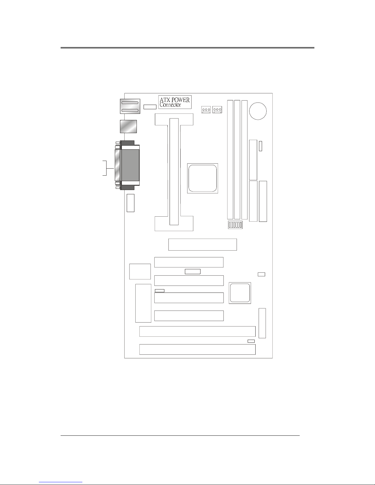
B683 Motherboard Layout Drawi g
Ch pter 2
SETUP GUIDE
˄˅ˆˇˈ
˄ˆ
˜˦˔ʳ˅
˜˦˔ʳ˄
ˣ˖˜ʳ˄
ˣ˖˜ʳ˅
ˣ˖˜ʳˆ
ˣ˖˜ʳˇ
˔˚ˣʳ˦˟ˢ˧
˕˜ˢ˦
˦˨ˣ˘˥
˜˂ˢ
˦˘ˡ˦ˢ˥
˦˟ˢ˧ʳ˄
˜˸˿
ˇˇ˃ʳ˕˫
˔˚ˣʳ˸
˜˸˿
ˣ˜˜˫ˇ
ˣ˖˜ʳ˸
˖ˣ˨ʳ˙˔˄
˦ˬ˦ʳ˄
˄ˆ
˄ˆ
˗˜ˠˠʳ˄
˗˜ˠˠʳ˅
˗˜ˠˠʳˆ
˜˗˘ʳ˅
˜˗˘ʳ˄ ˙˗˖
˝˕˔˧˄
ˆ˩
˕˴˸
˦˪˄
˝ˣ˄
˝ˣˆ
˥˧ˆ
˄
˅˅
˅
˅˄
˄
ˆ
˄
˄
ˆˇ
˄
˨˦˕ʳ˄˂˅
˧ˍʳ˟ˣ˧˄
˕ˍ˖ˢˠ˄˂˅
˄ˇ
˝ˣ˅
˄ˆ
˦ˬ˦˅
˥˧˄
˥˧˅
˧ˍʳˠ˸
˕ˍʳ˞˂˕
˝˪˥˄
˝˪ˢ˟˄
ˉ
˄
˅
ˉ
ˈ
˝˦˕˄
˄ˆ
˝ˣˇ
B683/B68
5
B680 Motherboard Layout Drawi g
˄˅ˆˇˈ
˄ˆ
˜˦˔ʳ˅
˜˦˔ʳ˄
ˣ˖˜ʳ˄
ˣ˖˜ʳ˅
ˣ˖˜ʳˆ
ˣ˖˜ʳˇ
˔˚ˣʳ˦˟ˢ˧
˕˜ˢ˦
˦˨ˣ˘˥
˜˂ˢ
˦˟ˢ˧ʳ˄
˜˸˿
ˇˇ˃ʳ˕˫
˔˚ˣʳ˸
˜˸˿
ˣ˜˜˫ˇ
ˣ˖˜ʳ˸
˖ˣ˨ʳ˙˔˄
˦ˬ˦ʳ˄
˄ˆ
˄ˆ
˗˜ˠˠʳ˄
˗˜ˠˠʳ˅
˗˜ˠˠʳˆ
˜˗˘ʳ˅
˜˗˘ʳ˄ ˙˗˖
˝˕˔˧˄
ˆ˩
˕˴˸
˦˪˄
˝ˣ˄
˝ˣˆ
˄
˅˅
˅
˅˄
˄
ˆ
˄
˄
ˆˇ
˄
˨˦˕ʳ˄˂˅
˧ˍʳ˟ˣ˧˄
˕ˍ˖ˢˠ˄˂˅
˄ˇ
˝ˣ˅
˄ˆ
˦ˬ˦˅
˧ˍʳˠ˸
˕ˍʳ˞˂˕
˝˪˥˄
˝˪ˢ˟˄
ˉ
˄
˅
ˉ
ˈ
˝˦˕˄
˄ˆ
˝ˣˇ

B683/B68
6
JUMPER & CONNECTOR SETTING
Connector Setting
KB1- PS/2 Keyboard/ PS/2 Mouse Co ector
Pi Descriptio
1 Keyboard Data
2 , 6 N.C.
3 Ground
4 +5V
5 Keyboard Clock
Pi Descriptio
1 Mouse Data
2 , 6 N.C.
3 Ground
4 +5V
5 Mouse Clock
USB1-U iversal Series Bus (USB) Co ectors
USB1 Pi Sig al Name USB2 Pi Sig al Name
1 USB VCC 1 USB VCC 1
2 USB Data - 2 USB Data -
3 USB DATA + 3 USB DATA +
4 USB GND 4 USB GND 1

B683/B68
7
JWR1 - Power Supply Co ector
Pi Descriptio
1,2,11 + 3.3 V
3,5,7,13,15,16,17 Ground
4,6,19,2 + 5 V
8 POWER GOOD
9 5VSB
1 +12 V
12 -12 V
14 PS-ON
18 - 5 V
JP2 – I frared Co ector : IR
Pi Sig al Name
1VCC
2SIRRX
3GND
4IRTX
JBAT1 – CMOS CLEAR
Descriptio Pi
Normal (default) 1-2
Clear CMOS 2-3
JWOL1 – WAKE ON LAN
Descriptio Pi
5V Stand-by 1
GND 2
LAN IN 3

B683/B68
8
LPT1- PRINTER Co ector
Pi Sig al Name Pi Sig al Name
1 Strobe- 14 AFD
2 Data Bit 15 Error
3 Data Bit 1 16 INIT
4 Data Bit 2 17 SLCTIN
5 Data Bit 3 18 GND
6 Data Bit 4 19 GND
7 Data Bit 5 2 GND
8 Data Bit 6 21 GND
9 Data Bit 7 22 GND
1 ACK 23 GND
11 Busy 24 GND
12 PE 25 GND
13 SLCT 26 GND
COM1,COM2 - Serial Co ectors
Pi Sig al Name Pi Sig al Name
1 DCD 6 DSR
2 SIN 7 RTS
3 SOUT 8 CTS
4 DTR 9 RI
5 GND 1 NC
JP4 Keyboard & PS/2 Mouse ON NOW Co ector
Pi Descriptio
1 VCC
2 K/B & PS/2 M.S.
3 5VSB
B683/B68
9
Note : 1-2 Dis bled (Def ult) 2-3 En bled
JSB1 – For Sideba d Sig als Co ector
Ex. Creative SB-LINK Connector
Pi Sig al Name
1 -GNTA
2,5 GND
3NA
4 -REQA
6 SERIRQ
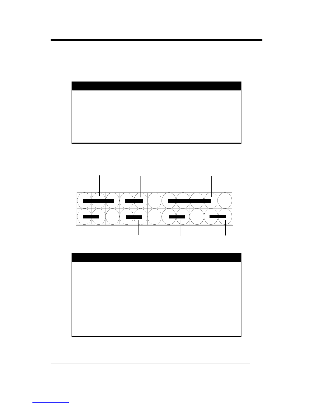
JP3 – OTHER JUMPER SETTING
Pi Name Descriptio
1 - 3 Reset Reset buttom
7 - 9 HDD_LED Hard Disk LED
13 - 15 EXT_SMI Suspend mode
19 - 21 SUS_LED Suspend LED
2 - 6 Power_LED Power LED
8 - 1 KEY_ Lock Key Lock
14 - 2 SPK Speaker
P2 P22
P1 P21
Power_LED KEY_Lock
SPK
Reset HDD_LED EXT_SMI SUS_LED

B683/B68
1
JP1 - POWER BUTTON
Pin Description
1-3 ON/OFF
B683/B68
11
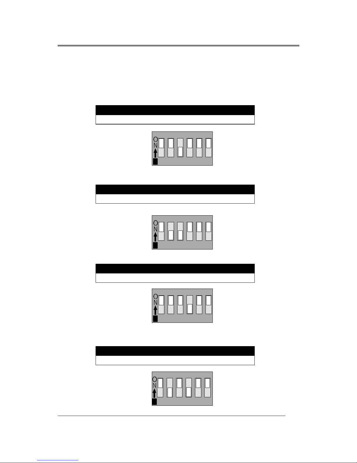
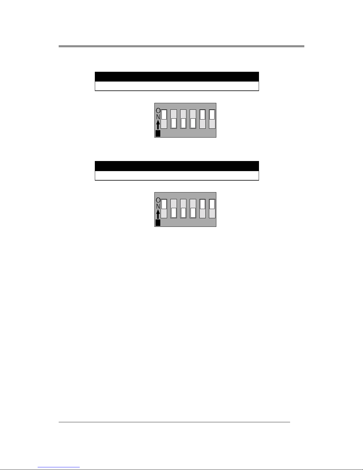
CPU TYPE Select
CPU Bus Speed - 66MHz part :
1. 200MHz
SW1-1 SW1-2 SW1-3 SW1-4 SW1-5 SW1-6
ON ON OFF ON ON ON
2. 233MHz
SW1-1 SW1-2 SW1-3 SW1-4 SW1-5 SW1-6
ON OFF OFF ON ON ON
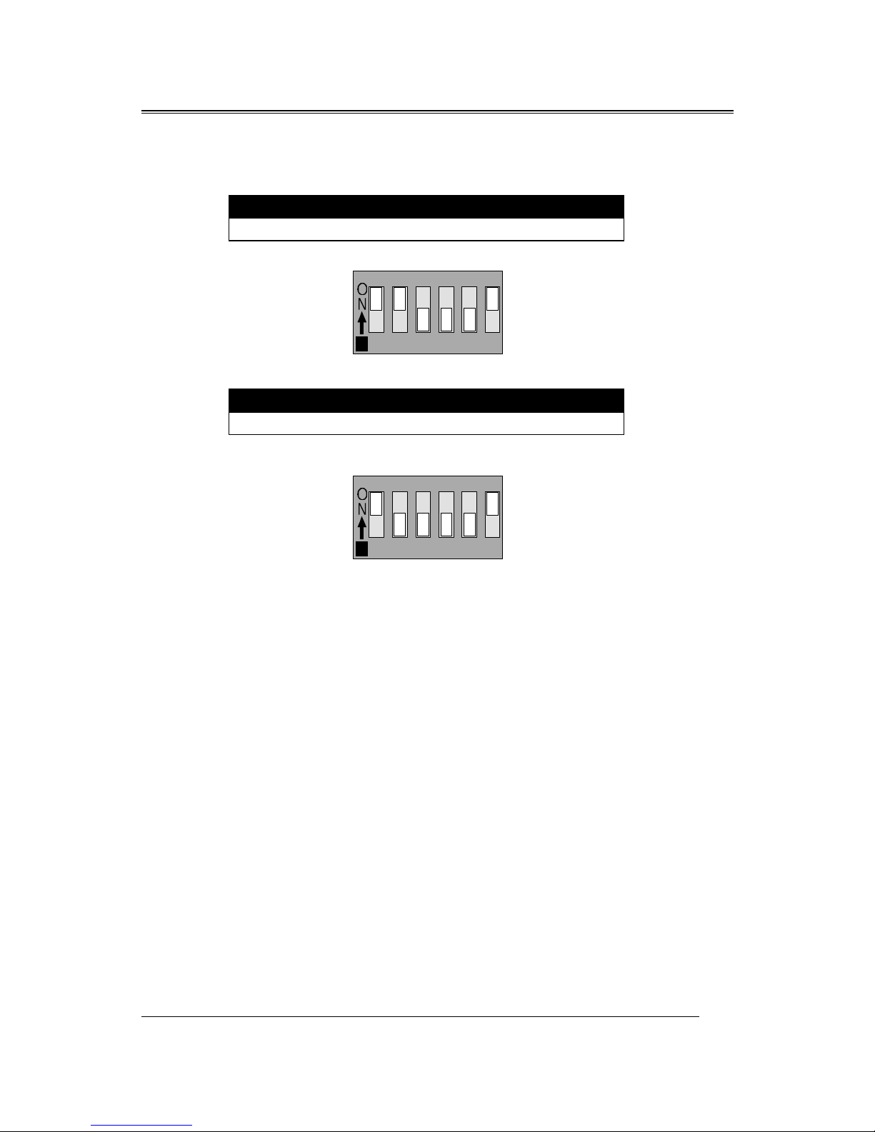
3. 266MHz
SW1-1 SW1-2 SW1-3 SW1-4 SW1-5 SW1-6
ON ON ON OFF ON ON
4. 300MHz
SW1-1 SW1-2 SW1-3 SW1-4 SW1-5 SW1-6
ON OFF ON OFF ON ON
12345
CTS 2 8-6 T8 8
6
12345
CTS 2 8-6 T8 8
6
12345
CTS 2 8-6 T8 8
612345
CTS 2 8-6 T8 8
6
12345
CTS 2 8-6 T8 8
6
B683/B68
12
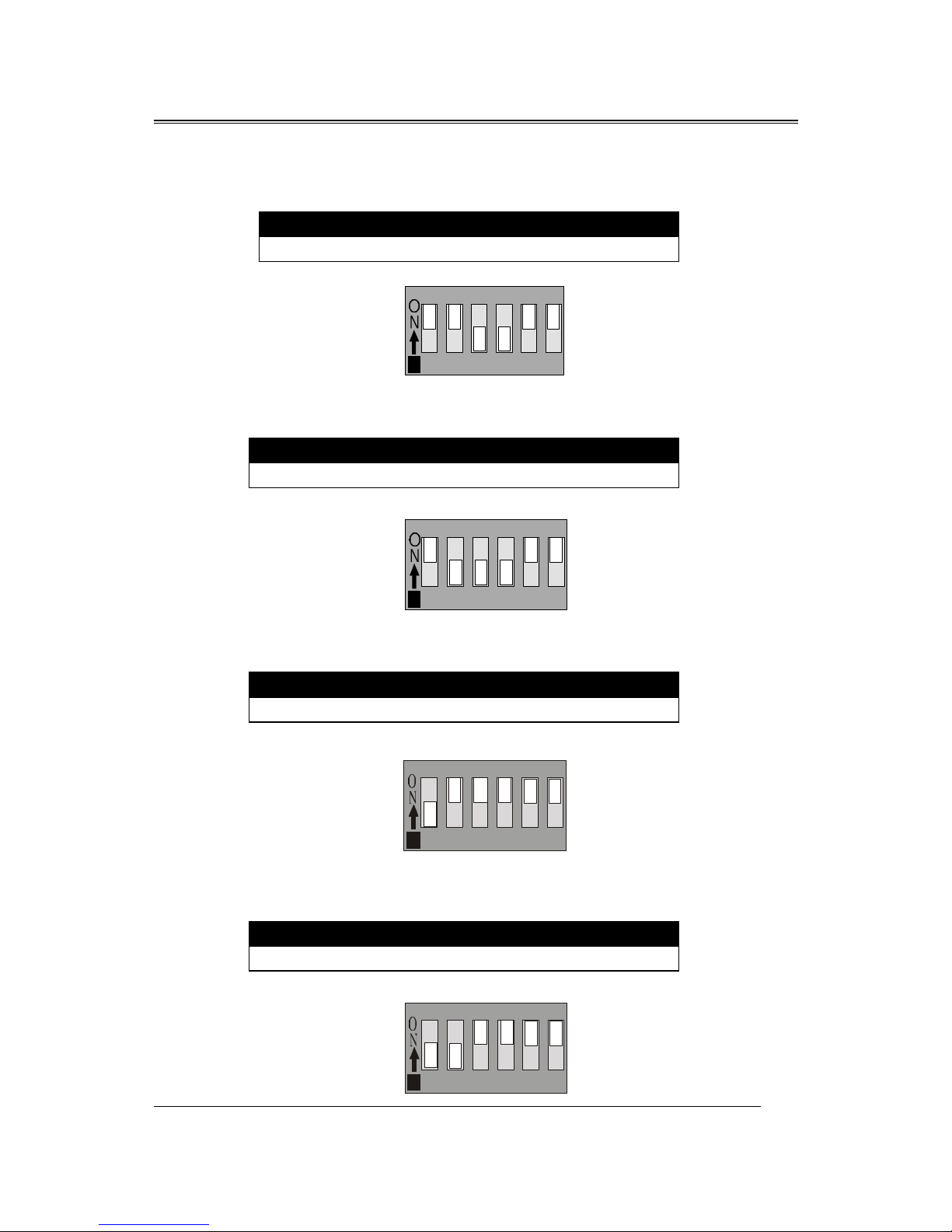
5. 333MHz
SW1-1 SW1-2 SW1-3 SW1-4 SW1-5 SW1-6
ON ON OFF OFF ON ON
6. 366MHz
SW1-1 SW1-2 SW1-3 SW1-4 SW1-5 SW1-6
ON OFF OFF OFF ON ON
7. 400MHz
SW1-1 SW1-2 SW1-3 SW1-4 SW1-5 SW1-6
OFF ON ON ON ON ON
8. 433MHz
SW1-1 SW1-2 SW1-3 SW1-4 SW1-5 SW1-6
OFF OFF ON ON ON ON
12345
CTS 2 8-6 T8 8
612345
CTS 2 8-6 T8 8
6
12345
CTS 2 8-6 T8 8
612345
CTS 2 8-6 T8 8
6
23456
DUT!319.7!U919
723456
DUT!319.7!U919
7
23456
DUT!319.7!U919
723456
DUT!319.7!U919
7
B683/B68
13
9. 466MHz
SW1-1 SW1-2 SW1-3 SW1-4 SW1-5 SW1-6
OFF ON OFF ON ON ON
10. 500MHz
SW1-1 SW1-2 SW1-3 SW1-4 SW1-5 SW1-6
OFF OFF OFF ON ON ON
12345
CTS 2 8-6 T8 8
612345
CTS 2 8-6 T8 8
6
12345
CTS 2 8-6 T8 8
612345
CTS 2 8-6 T8 8
6

B683/B68
14
CPU Bus Speed - 100MHz part :
1. 300MHz
SW1-1 SW1-2 SW1-3 SW1-4 SW1-5 SW1-6
ON ON OFF ON OFF OFF
2. 350MHz
SW1-1 SW1-2 SW1-3 SW1-4 SW1-5 SW1-6
ON OFF OFF ON OFF ON
3. 400MHz
SW1-1 SW1-2 SW1-3 SW1-4 SW1-5 SW1-6
ON ON ON OFF OFF ON
4. 450MHz
SW1-1 SW1-2 SW1-3 SW1-4 SW1-5 SW1-6
ON OFF ON OFF OFF ON
12345
CTS 2 8-6 T8 8
6
12345
CTS 2 8-6 T8 8
6
12345
CTS 2 8-6 T8 8
612345
CTS 2 8-6 T8 8
6
12345
CTS 2 8-6 T8 8
612345
CTS 2 8-6 T8 8
6
12345
CTS 2 8-6 T8 8
612345
CTS 2 8-6 T8 8
6
B683/B68
15
5. 500MHz
SW1-1 SW1-2 SW1-3 SW1-4 SW1-5 SW1-6
ON ON OFF OFF OFF ON
6. 550MHz
SW1-1 SW1-2 SW1-3 SW1-4 SW1-5 SW1-6
ON OFF OFF OFF OFF ON
12345
CTS 2 8-6 T8 8
612345
CTS 2 8-6 T8 8
6
12345
CTS 2 8-6 T8 8
612345
CTS 2 8-6 T8 8
6

B683/B68
16
CPU TYPE SELECT LIST
SW1-1,2,3,4 (For RATIO select)
RATIO SW1-1 SW1-2 SW1-3 SW1-4
3. ON ON OFF ON
3.5 ON OFF OFF ON
4. ON ON ON OFF
4.5 ON OFF ON OFF
5. ON ON OFF OFF
5.5 ON OFF OFF OFF
SW1-5 (For BUS clock)
CLOCK SW1-5
66 MHz ON
1 MHz OFF
SW1-6 (CPU BUS Clock m nu l / Auto detect)
CLOCK SW1-6
Default (Auto Detect) ON
Force BUS CLOCK up to 1 MHz OFF
FAN CONNECTOR
CPU FA1
GNDFan InFan Out
SYS 1
GND Fan In
Fan Out
SYS 2
GND
Fan In Fan Out

B683/B68
17
MEMORY INSTALLATION
No jumper setting is necessary for DRAM setting, BIOS will check
DRAM type and size automatically. B683 motherboard contains 3 by
168-pin DIMM sockets(DIMM1,DIMM2,DIMM3). B683 motherboard has
table-free ( or auto-bank ) feature and user can install DIMM into any
bank. The three DIMMs Sockets for system memory expansion from
8MB to 384 MB. Each bank provides 64-bit wide data path.
NOTE: Samples of System Memory Combi atio s Optio s
DIMM1 DIMM2 DIMM3 TOTAL
8MB --- --- 8MBytes
--- 8MB --- 8MBytes
--- --- 8MB 8MBytes
8MB 8MB --- 16MBytes
--- 8MB 8MB 16MBytes
8MB --- 8MB 16MBytes
16MB --- --- 16MBytes
--- 16MB --- 16MBytes
--- --- 16MB 16MBytes
8MB 8MB 8MB 24MBytes
16MB 8MB --- 24MBytes
16MB --- 16MB 32MBytes
16MB 16MB --- 32MBytes
--- --- 32MB 32MBytes
--- 32MB --- 32MBytes
32MB --- --- 32MBytes
8MB 16MB 16MB 4 MBytes
32MB 32MB --- 64MBytes
--- 32MB 32MB 64MBytes
64MB --- --- 64MBytes
64MB 64MB --- 128MBytes
64MB 64MB --- 128MBytes
: : : :
: : : :
128MB 128MB 128MB 384MBytes

B683/B68
17
Award BIOS ROM has a built-in Setup program that allows users to
modify the basic system configuration. This type information is stored in
battery-backed RAM so that it retains the Setup information when the power is
turned off.
ENTERING SETUP
Power on the computer and press <Del> immediately will allow you to
enter Setup. The other way to enter Setup is to power on the computer , when
the below message appears briefly at the bottom of the screen during the POST
(Power On Self Test), press <Del> key or simultaneously press <Ctrl>, <Alt>,
and <Esc> keys.
TO ENTER SETUP BEFORE BOOT PRESS CTRL-ALT-ESC OR
DEL KEY
If the message disappears before you respond and you still wish to enter
Setup, restart the system to try again by turning it OFF then ON or pressing the
"RESET" button on the system case. You may also restart by simultaneously
press <Ctrl>, <Alt> and <Del> keys. If you do not press the keys at the correct
time and the system does not boot , an error message will be displayed and you
will again be asked to,
PRESS F1 TO CONTINUE, CTRL-ALT-ESC OR DEL TO ENTER
SETUP
Co trol Keys
Up Arrow Move to previous item
Down Arrow Move to next item
Left Arrow Move to the item in the left hand
Ch pter 3
AWARD BIOS SETUP

B683/B68
18
Right Arrow Move to the item in the right hand
Esc Key Main Menu Quit and not to save changes to
CMOS
Status Page setup menu and Option Page
Setup Menu Exit current page and return to
Main Menu
PgUp Key Increase the numeric value or make changes
PgDn Key Decrease the numeric value or make changes
F1 Key General help, only for Status Page Setup
Menu and Option Setup
Menu
F2 Key Change color from total 16 colors
F3 Key Calendar, only for Status Page Setup Menu
F4 Key Reserved
F5 Key Restore the previous CMOS value from
BIOS, only for Option
Page Setup Menu
F6 Key Load the default CMOS value from BIOS
default table, only for
Option Page Setup Menu
F7 Key Load the default
F8 Key Reserved
F9 Key Reserved
F1 Key Save all the CMOS changes, only for Main
Menu
Getti g Help
Mai Me u
The on-line description of the highlighted setup function is displayed at the
bottom of the screen.
Status Page Setup Me u/Optio Page Setup Me u
Press F1 to pop up a small help window that describes the appropriate keys
to use and the possible selections for the highlighted item. To exit the Help
Window press <Esc>.
This manual suits for next models
1
Table of contents
Other Procomp Motherboard manuals


Popular Motherboard manuals by other brands

Asus
Asus A7V-VE Quick start manual

Gigabyte
Gigabyte Z690 AORUS MASTER manual

3A Game Electronic Technology
3A Game Electronic Technology PANDORA BOX CX Quick user manual

Gigabyte
Gigabyte 8S648FXP-RZ user manual

Infineon
Infineon Cypress CY6611 quick start guide

Linear Technology
Linear Technology DC875 quick start guide


