Procomp BIW1A Series User manual

BIW1Aseries
~0~
Safety and Regulatory Information
Notice for the USA
FCC Part 15: This equipment has been tested and found to comply with
the limits for a class B digital device, pursuant to Part 15 of the CC Rules.
These limits are designed to provide reasonable protection against harmful
interference in a residential installation. This equipment generates, uses, and
can radiate radio frequency energy and, if not installed and used in
accordance with the instructions, may cause harmful interference to radio
communications. However, this notice is not a guarantee that interference
will not occur in a particular installation.
CAUTION: To comply with the limits for the class B device, pursuant
to Part 15 of the CC Rules, this device must be installed in computer
equipment certified to comply with the Class B limits.
All cables used to connect the computer and peripherals must be shielded and
grounded. Operation with non-certified computers or non-shielded cables
may result in interference to radio or television reception.
Any changes or modifications not expressly approved by the grantee of
this device could void the user’s authority to operate the device.
COPYRIGHT: This publication, including all photographs, illustrations
and software, is protected under international copyright laws, with all rights
reserved. Neither this manual, nor any of the material contained herein, may
be reproduced without the express written consent of the manufacturer.
DISCLAIMER: The information in this document is subject to change
without notice. The manufacture makes no representations or warranties with
respect to the contents hereof and specifically disclaims any implied
warranties of merchantability or fitness for any particular purpose.

BIW1Aseries
~1~
TABLE OF CONTENTS
CH1. MOTHERBOARD FEATURE ..................................................... 2
1.1 ABOUT THE MANUAL ...................................................... 4
1.2 SPECIFICATIONS............................................................. 5
1.3 DIFINITION OF B C1Aseries MODEL ............................... 7
1.4 POWER OFF CONTROL SOFTWARE ............................ 7
1.5 PACKAGING CHECK LIST............................................... 8
CH2. SETUP GUIDE............................................................................ 9
2.1 MOTHERBOARD LAYOUT............................................... 9
2.2 CONNECTOR & JUMPER REFERENCE CHART ......... 10
2.3 THE SETUP STEPS........................................................ 11
2.3-1 JUMPER & CONNECTOR SETTING ................... 11
2.3-2 MEMORY INSTALLATION.................................... 22
2.3-3 HOW TO INSTALL THE CPU ............................... 25
2.3-4 INSTALLING THE MOTHERBOARD.................... 27
2.3-5 INSTALLING THE INTERFACE CARD ................ 28
2.3-6 INSTALLING ACCESSORY CABLES .................. 29
CH3. AWARD BIOS SETUP ............................................................. 31
3.1 THE MAIN MENU............................................................ 33
3.2 STANDARD CMOS SETUP............................................ 35
3.3 AD ANCED BIOS FEATURES SETUP.......................... 37
3.4 AD ANCED CHIPSET FEATURES SETUP .................. 40
3.5 INTEGRATED PERIPHERALS ....................................... 43
3.6 POWER MANAGEMENT SETUP ................................... 46
3.7 PNP / PCI CONFIGURATION SETUP............................ 49
3.8 PC HEALTH STATUS ..................................................... 50
3.9 FREQUENCY / OLTAGE CONTROL ........................... 51
3.10 LOAD FAIL-SAFE DEFAULTS...................................... 52
3.11 LOAD OPTIMIZED DEFAULTS.................................... 52
3.12 SUPER ISOR/USER PASSWORD SETTING ............. 52
3.13 SA E AND EXIT SETUP OPTION ............................... 53
3.14 EXIT WITHOUT SA ING OPTION ............................... 49
CH4. SOFTWARE SETUP ................................................................ 54
4.1 INSTALLING THE IDE BUS MASTER DRI ER ............. 54
4.2 INSTALLING THE INTEL 810 GA DRI ER.................. 56
4.3 INSTALLING THE ADI 1881 AUDIO DRI ER....................57

BIW1Aseries
~2~
Based on Intel’ s 810 GMCHset & ICH (82810-DC100 + 82801)
chipsets, the BIW1A is an advanced motherboard that comes with onboard
audio and video capabilities, an audio modem riser slot, a 4MB BIOS that
includes built-in anti-virus protection and UltraDMA/66 technology for
lightning-fast IDE transfer speeds.
The BIW1A is an ATX-sized motherboard, measuring 305mm by 173
mm, and it uses a four-layer printed circuit board. Designed for a Socket 370
CPU, the BIW1A also includes two DIMM sockets for the addition of up to
512MB of memory. The bus system supports speeds of 66MHz to 100MHz,
which means either inexpensive 66MHz or high-performance 100MHz
memory modules can be added to the system.
In addition to its 32-bit onboard sound functionality, the BIW1A comes
with an integrated VGA adapter with 2D and 3D graphics engines and 4MB
of onboard video memory. An audio modem riser slot is included as well as
hardware monitoring and wake-on LAN capabilities. Built-in anti-virus
protection ensures you will maintain a clean operating environment free of
unwanted viruses. The BIW1A also features UltraDMA/66 technology,
which allows for Master IDE transfer rates of up to 66MB/sec.
The BIW1A is a powerful platform that leverages the benefits of a low-
cost system with high-performance functionality, and we are confident you
will see for yourself how convenient this motherboard is when you assemble
your system.
FEATURES
Full-funct on Process ng -
Intel’ s new-generation chipset—t he Intel 810 GMCHset —supports all Socket
370 and compatible processors. The motherboard comes with many excellent
functions built in, such as an audio modem riser slot, onboard 3D graphics,
UltraDMA/66 support and built-in anti-virus protection. The motherboard
enables users to move up to optimized performance at a low cost. Processor
Chapter 1
Motherbo rd Fe ture Introduction

BIW1Aseries
~3~
speed configurations are automatically set through the board’ s firmware,
which means changing switch or jumper settings on the motherboard is not
necessary.
H gh Performance -
The board has two DIMM sockets for the installation of 168-pin, 3.3V non-
buffered DIMM memory modules. The DIMM memory modules must be
SDRAM memory chips. The board supports a memory bus of 100/66MHz,
and each DIMM socket can accept modules up to 256MB in capacity for up
to 512MB of total system memory.
3D Graph c VGA & Clear 32-b t Aud o Bu lt In -
ull multimedia function is integrated onto the motherboard, which means
you won’ t need to spend extra money on additional adapters, processors and
cards. Either 2D or 3D graphics can be displayed, and the motherboard
comes with a 4MB onboard SDRAM display cache that supports 1024 X 768
X 16-bit 3D graphics and 1600 X 1200 X 8-bit color 2D graphics. AC’ 97
DAC/ADC, which is built into the audio CODEC, reduces noise and results
in improved audio quality and performance for a signal to noise ratio of
+90dB. These features greatly improve voice synthesis and recognition.
Double or Quadruple IDE Transfer Speeds -
IDE transfers using UltraDMA/33 Bus Master IDE technology can handle
rates of up to 33MB/sec., while UltraDMA/66 technology supports IDE
transfer speeds of 66MB/sec. Best of all, this technology is compatible with
existing ATA-2 IDE specifications, so there is no need to upgrade current
IDE devices or cables.
Slot Expans on Opt ons -
The motherboard has a full set of expansion slots, with five usable slots: four
32-bit PCI slots and one 8/16-bit ISA slot. The ISA slot and one PCI slot
share the same physical area, which means you cannot use both at the same
time.(BIW1A-I only)
Integrated I/O -
With its built-in Windbond I/O chip, this motherboard has a comprehensive
set of integrated I/O ports. The I/O port array features PS/2 keyboard and
mouse ports, a parallel port, two USB ports, two serial ports, a monitor port,
a game/MIDI port, and three audio jacks. You may also use the built-in

BIW1Aseries
~4~
motherboard header to add in an infrared port. In addition, the motherboard
has two PCI-IDE channels and a floppy disk drive interface.
ACPI Ready -
APCI (Advanced Configuration and Power Interface) technology provides
for more energy saving functions for future operating systems supporting OS
Director Power Management (OSPM) functionality. With these features
implemented in the operating system, your system can be ready around the
clock while meeting all energy-saving standards.
Programmable F rmware -
The motherboard includes a 4MB Award BIOS that allows CPU
parameters to be set through the BIOS. The firmware BIOS includes a new,
easy-to-use interface that gives users more control over their system’ s
performance. The fully programmable firmware provides enhanced system
features and allows users to set power management, CPU and memory timing
levels, as well as LAN and modem wake-up alarms.
1.1 ABOUT THE MANUAL
The manual consist of the following chapters:
CH1. Motherboard features introduction – Introduce the features of
BIW1Aseries and the checklist of items that are shipped with the
package.
CH2. Setup guide – Let you learn how to install the motherboard and get
your system up and running.
CH3. Award BIOS setup – Configure the BIOS of motherboard for optimum
performance.
CH4. Software setup – Let you learn how to install the software drivers and
support programs that are provided with this motherboard.

BIW1Aseries
~5~
1.2 SPECIFICATIONS
Chipset Intel 810 GMCHset & ICH (82810-DC100 + 82801)
solution.
Processor Socket 370 Support.
Intel Celeron processor 300MHz ~ 500MHz and higher.
Bus
Architecture PCI/ISA.
Clock Gener tor 66.8, 68.3, 70, 75, 100 up to 150 MHz.
DRAM Modules
2 x 168 pin DIMM Sockets
Support Maximum Memory Size to 512 MB SDRAM
PC100 SDRAM.
BIOS
4Mbit irmware Hub (82802AB).
Award PnP BIOS with enhanced ACPI feature for PC98
compliance
Supports 120MB ATAPI floppy disk.
Supports ZIP disk drive.
Supports multi-boot from IDE, SCSI, CD-ROM and
DD.
Supports software clock frequency control.
On Bo rd VGA
Port
Graphics and Memory Controller Hub (82810-DC100
GMCH).
Gamma Corrected Video.
DDC2B Compliant.
Integrated 2D & 3D Graphics Engines.
2D Graphics Up to 1600 x 1200 in 8bit Color at 85Hz
Refresh.
4M Display Cache.
Integrated 24 bit 230MHz DAC.
On Bo rd Sounds
AC97 Codec Compliant.
1 x CD audio in.
1 x Mic in.
1 x Line in.
1 x Speaker out.

BIW1Aseries
~6~
On Bo rd I/O
1 x Digital Video.
1 x loppy port (up to 2.88MB, 3 mode floppy supported
& LS-120).
2 x Serial ports.
1 x Parallel port (SPP/EPP/ECP).
2 x USB.
1 x PS/2 mouse.
1 x PS/2 keyboard.
1 x IrDA.
1 x Joystick.
On Bo rd IDE
Port
Dual Ultra DMA66 IDE ports.
ATAPI IDE CD-ROM & LS-120.
Exp nsion slot
1 x AMR Riser slot
4 x 32-bit PCI slots.
1 x 16-bit ISA slot. (Optional)
ICH
I/O Controller Hub (82801AA I/O).
Supports PCI Rev 2.2 Specification.
Supports PCI 6 Master Devices on PCI.
Supports IDE Ultra DMA66 Mode.
AC 97 2.1 Link Compliant.
Low Pin Count (LPC) I/ .
SMbus Interface.
Power Management Logic.
irmware Hub I/ .
LPC I/F Chip &
H rdw re
Monitoring
Winbond W83627H .
PCI to ISA Bridge
set W83628 & W83629D. (Optional)
Adv nced
Fe tures
1. Supports keyboard & mouse power on feature with
ATX power V2.01
3. Ring Indicate header.
4. ACPI 1.0 Compliant.
5. APM Rev 1.2 Compliant.
Form F ctor ATX Size (173mm x 305mm)

BIW1Aseries
~7~
1.3 DEFINITION OF BIW1Aseries MODEL
BIW1Aseries have different function for meeting customer demand. When you
purchase the motherboard of BIW1Aseries you just follow below description to
know which extra function you have.
1. ind the model of BIW1Aseries you have purchased.
2. Check having any words after the “Dash” mark of model.
3. Review these words show what Extra functions / Optional unctions.
Codes Definition
Code Description
I ISA Slot
Example:
♦ BIW1A-I Ш There is a word “I” after the Dash mark, so the extra function
is with ISA Slot.
It is easily to differentiate between varieties of BIW1Aseries motherboards.
1.4 POWER OFF CONTROL SOFTWARE
The motherboard design supports the software power off Control feature
through the SMI code in the BIOS under WIN98/95 operating system
environment. It is an ATX form factor, so you should use ATX power
supply.
irst, connect the power switch cable (provided by the ATX case
Supplier) to the connector [ PWBT ] on the motherboard (Please refer to the
following illustration). In the BIOS screen of “POWER MANAGEMENT
SETUP”, choose “User Defined”(or min power saving or Max power saving)
in “POWER MANAGEMENT” and choose “Yes” in “PM Control by APM”.

BIW1Aseries
~8~
Note: BIOS Setup. Please refer the “Chapter 3 Award BIOS Setup”
In Windows 98/95, under the “SHUT DOWN” option, the computer’ s
power will switch off automatically and put the PC in a suspend mode. This
will be indicated by a blinking power light. To restart the system, simply
press the Power Button.
1.5 PACKAGING CHECK LIST
The Motherboard comes securely packed in a gift box and shipping carton.
If any of the above items are missing or damaged, please contact your
supplier.
The motherboard contains:
Q’ TY Description
1 Motherboard : With Intel 810 GMCHset & ICH
(82810-DC100 + 82801) chipset
1 Driver : CD-Title w/Installation label
• PC-Cillin Software
• Motherboard Bus master Driver
• Audio Driver
1 Cable : IDE Cable
1 Cable : loppy Cable
1 Cable : COM2 Cable
1 User’ s guide : PC-Cillin
1 Manual : User’ s manual
PS_BT
BIW1Aseries
~9~
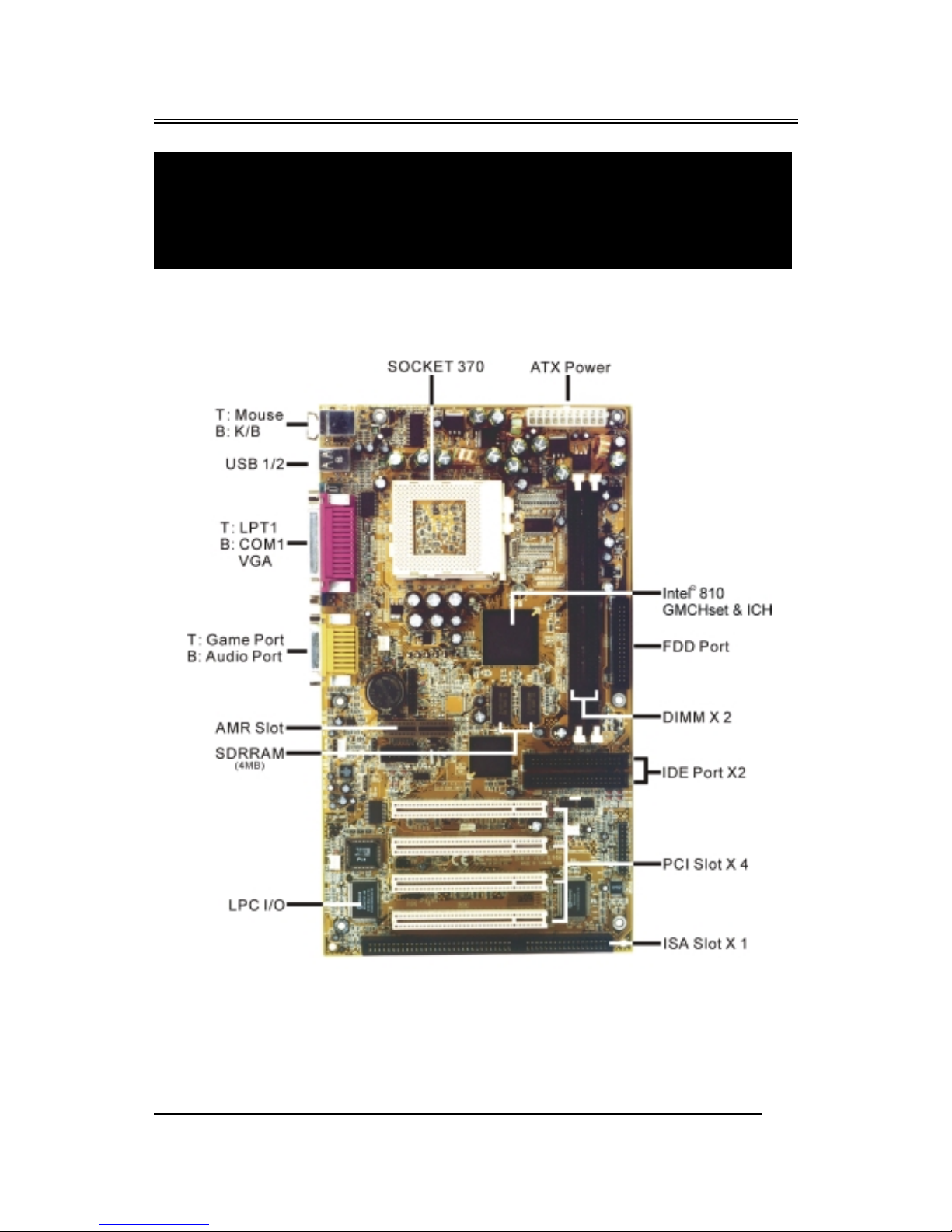
2.1 M therb ard lay ut
Chapter 2
Setup Guide

BIW1Aseries
~10~
2.2 C nnect r & Jumper Reference Chart
Intel
810 GMCH
set
S
USB 1/2
T: LPT1
B: COM1
GA
T : Mouse
B : K/B
T: Game Port
B: Audio Port
PCI 2
KB USB COM1 GA
MS
LPT
Speaker out
Line In
MIC
MIDI/Game port
Connector Front View
ISA 1
PCI 1
3
Battery
Socket 370
JP1
JP2
JP9
CPU FAN
AMR
COM2
J15
CD-IN
JP3
KQ2
KQ3
KQ4
KQ2
KQ3
KQ4
PCI 3
PCI 4
JP4
FAN3
FAN2
JP6
WOL
IDAr
J23
BIW1Aseries
~11~
2.3 The setup steps
Please refer to the following steps to setup your computer:
I. Refer to the Jumper Setup section to set up the jumpers correctly.
II. Install the DIMM modules on the motherboard; be sure to set up
safely.
III. Install the CPU on the motherboard (please refer to the CPU
installation manual).
IV. Choose a case and install the motherboard into this case.
V. Plug in all the interface cards of your system equipment.
VI. Connect the cable, power supply and other message lines in the
correct position.
VII. Reboot, and enter the Award BIOS setup Menu to correct the
definitions.
VIII. Turn on the power and set up your computer system software.
2.3-1 Jumper & Connector Setting
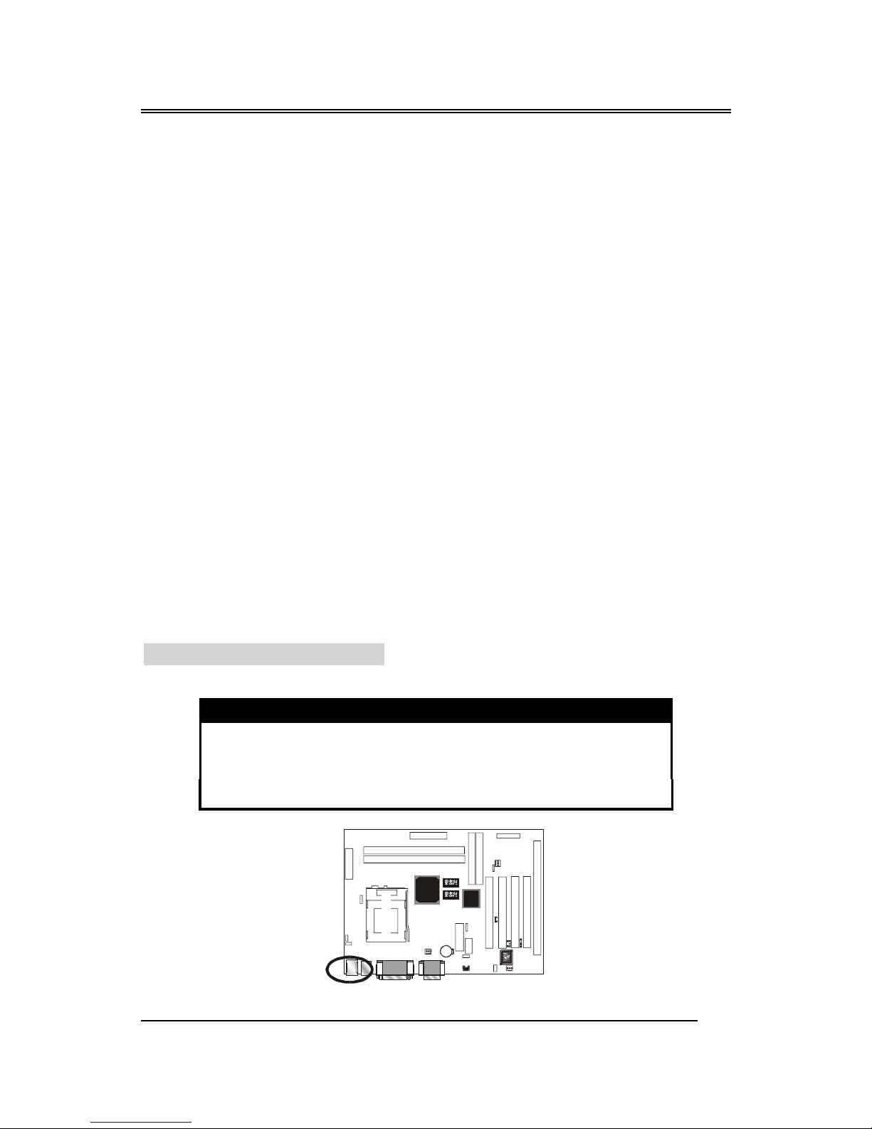
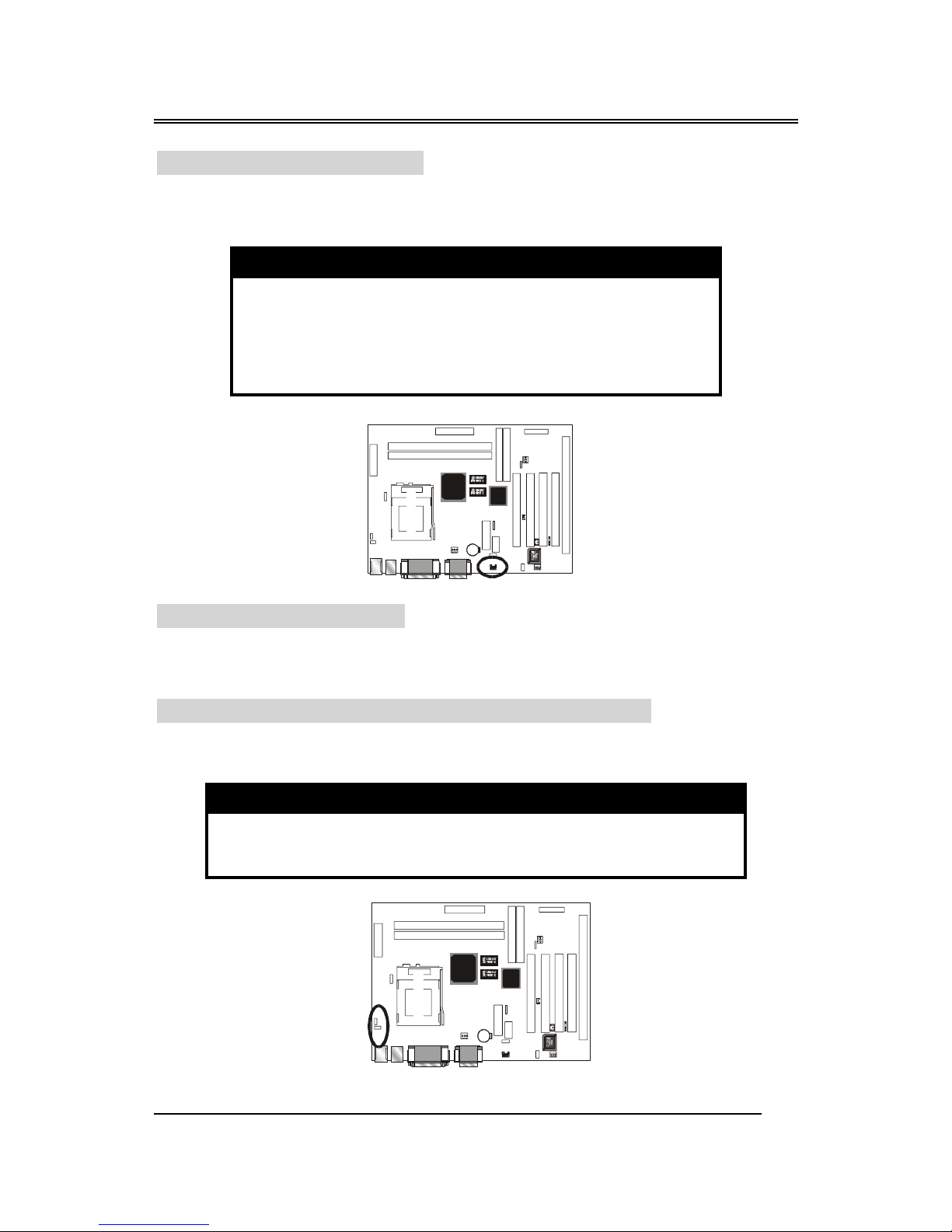
PS/2 Keybo rd Connector Color : Purple ; Panton : 2715C
This connector can connect PS/2 Keyboard and has better performance.
Pin Description Pin Description
1 Keyboard Data 2,6 N.C.
3 Ground 4 +5
5 Keyboard Clock
In t el
810 GMCH
set
S
3
Battery
Socket 370
KQ2
KQ3
KQ4
KQ2
KQ3
KQ4
JP6
IDAr

BIW1Aseries
~12~
PS/2 Mouse Connector Color : Green ; Panton : 3395C
This connector can connect PS/2 Mouse and has better performance.
Pin Description Pin Description
1 Mouse Data 2,6 N.C.
3 Ground 4 +5
5 Mouse Clock
ATX Power Supply Connector
This connector allows the motherboard to draw the power form ATX
power supply. It requires an ATX power supply of 250 watt at least.
Pin Description Pin Description
1,2,11 + 3.3 3,5,7,13,
15,16,17
Ground
4,6,19,20 + 5 8 POWER GOOD
9 5 SB 10 +12
12 -12 14 PS-ON
18 - 5
In t el
810 GMCH
set
S
3
Battery
Socket 370
KQ2
KQ3
KQ4
KQ2
KQ3
KQ4
JP6
IDAr
Intel
810 GMCH
set
S
3
Battery
Socket 370
KQ2
KQ3
KQ4
KQ2
KQ3
KQ4
JP6
IDAr
BIW1Aseries
~13~
Printer Connector Color : Burgundy ; Panton : 235C
This Connector can transfer the data to printer for printing on paper.
Pin Sign l N me Pin Sign l N me
1 Strobe- 14 AFD
2 Data Bit 0 15 Error
3 Data Bit 1 16 INIT
4 Data Bit 2 17 SLCTIN
5 Data Bit 3 18 GND
6 Data Bit 4 19 GND
7 Data Bit 5 20 GND
8 Data Bit 6 21 GND
9 Data Bit 7 22 GND
10 ACK 23 GND
11 Busy 24 GND
12 PE 25 GND
13 SLCT 26 GND
Intel
810 GMCH
set
S
3
Battery
Socket 370
KQ2
KQ3
KQ4
KQ2
KQ3
KQ4
JP6
IDAr

BIW1Aseries
~14~
COM1–Seri l Connectors Color : Turquoise ; Panton : 322C
These connectors allow mouse or the other device which use this type
connector for transferring data between computer and devices.
Pin Sign l N me Pin Sign l N me
1 DCD 6 DSR
2 SIN 7 RTS
3 SOUT 8 CTS
4 DTR 9 RI
5 GND 10 NC
VGA – VGA Out Connector Color : Blue ; Panton : 661C
This connector is for the external monitor. Use this port to connect to a
VGA or higher resolution display monitor.
Pin Sign l N me Pin Sign l N me
1 RED Signal 9 N.C.
2 GREEN Signal 10 GND
3 BLUE Signal 11 N.C.
4 N.C. 12 Display data channel data
5 GND 13 Horizontal Sync
6 GND 14 ertical Sync
7 GND 15 Display data channel clock
8 GND
Intel
810 GMCH
set
S
3
Battery
Socket 370
KQ2
KQ3
KQ4
KQ2
KQ3
KQ4
JP6
IDAr
Intel
81 0 GMC H
set
S
3
Battery
Socket 370
KQ2
KQ3
KQ4
KQ2
KQ3
KQ4
JP6
IDAr

BIW1Aseries
~15~
USB- Univers l Seri l Bus (USB1, USB2) Connectors
Color : Black ; Panton : 426C
These connectors allow the device which use this type connector for
transferring information between computer and devices.
USB1 Pin Sign l N me USB2 Pin Sign l N me
1 USB CC 0 1 USB CC 1
2 USB Data - 2 USB Data -
3 USB Data + 3 USB Data +
4 USB GND 0 4 USB GND 1
5 GND 5 GND
GAME/MIDI – For G me or MIDI Connector
Color: Gold ; Panton : 131C
You can use this port to connect a joystick or a MIDI device to your
system.
Pin Sign l
N me Pin Sign l
N me Pin Sign l
N me
1 CC6 TB 11 TC
2 SWA 7 SWD 12 MSD
3TA8 CC 13 TD
4 GND 9 CC 14 SWD
5 GND 10 SWC 15 MSI
In t el
81 0 GMC H
set
S
3
Ba t t e r y
Socket 370
KQ2
KQ3
KQ4
KQ2
KQ3
KQ4
JP6
IDAr
Intel
810 GM CH
set
S
3
Battery
Socket 370
KQ2
KQ3
KQ4
KQ2
KQ3
KQ4
JP6
IDAr
BIW1Aseries
~16~
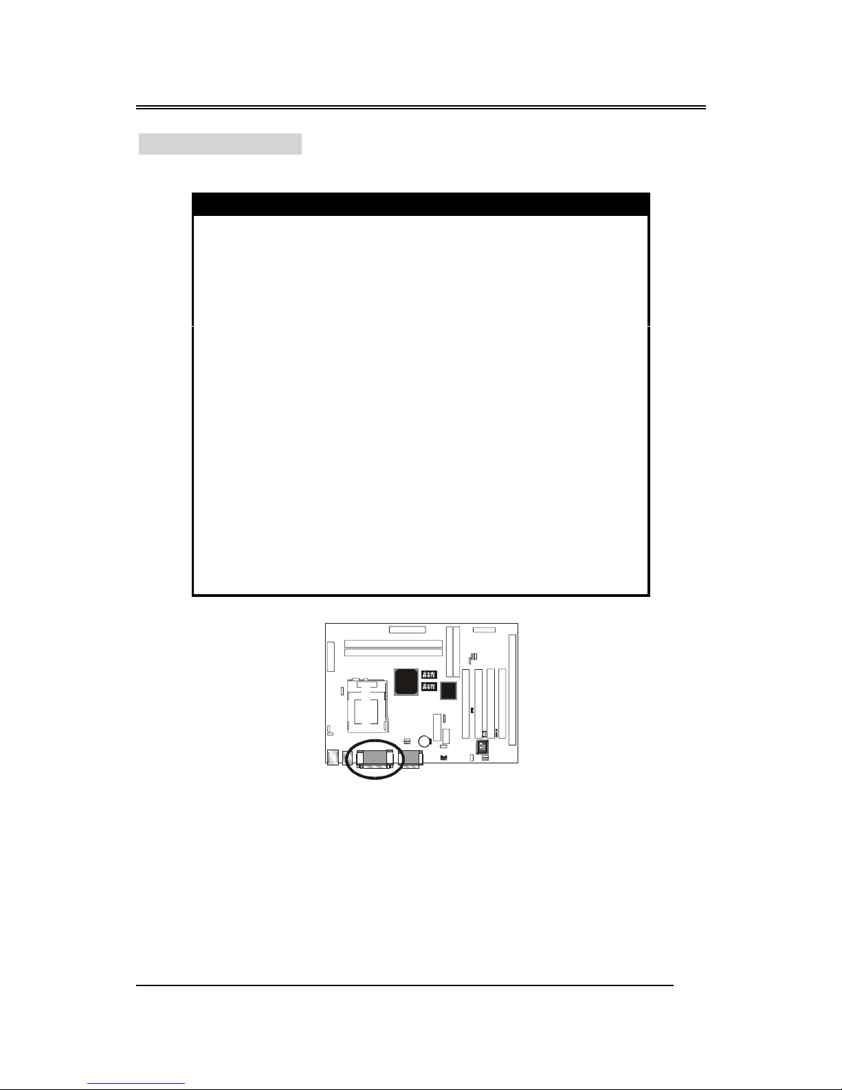
IrDA - Infr red Connector: IR
This connector is used to connect IR Device.
Pin Sign l N me
1 CC
2NC
3 SIRRX
4 GND
5 IRTX
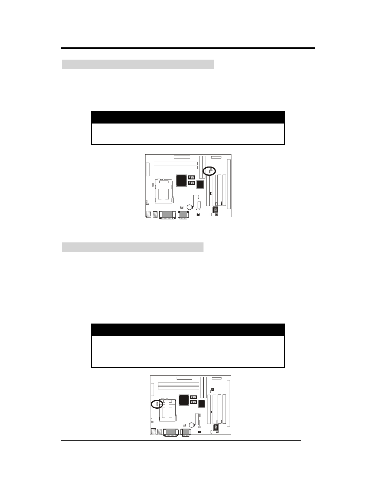
WOL – W ke-up On LAN Connector
This connector is used to connect an add-in NIC ( Network Interface
Card ) which gives WOL function to the motherboard. Enable this function
for remotely managing PC on a network. When a PC receives the wake up
command during sleep, the LAN controller will wake up the PC.
Pin Sign l N me
1 5 SB
2 GND
3 LID
Intel
810 GMCH
set
S
3
Battery
Socket 370
KQ2
KQ3
KQ4
KQ2
KQ3
KQ4
JP6
IDAr
Intel
810 GMCH
set
S
3
Battery
Socket 370
KQ2
KQ3
KQ4
KQ2
KQ3
KQ4
JP6
IDAr
BIW1Aseries
~17~
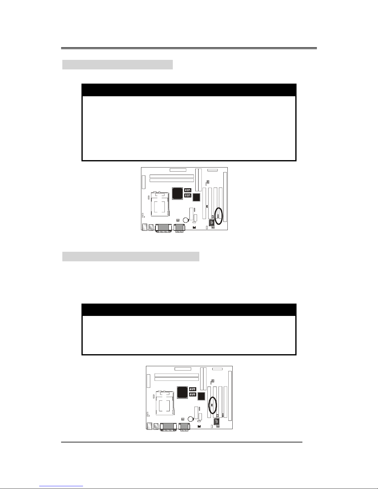
CD-IN: CD udio Connector
This connector is used to connect CD-ROM audio output to
motherboard, through this, the CD audio can output to audio chip directly.
Pin Description
1 Left
2 Ground
3 Ground
4 Right
JP1: Jump for Cyrix CPU
This jump only is reserved for Cyrix CPU, but the Cyrix CPU is not
available yet.
JP2 – Keybo rd & PS/2 Mouse ON NOW Connector
This connector is used to enable keyboard & PS/2 mouse power on with
hot keys or mouse button.
Pin Sign l N me
1-2 Enable
2-3 Disable
Intel
810 GMCH
set
S
3
Battery
Socket 370
KQ2
KQ3
KQ4
KQ2
KQ3
KQ4
JP6
IDAr
Intel
810 GMCH
set
S
3
Batte ry
Socket 370
KQ2
KQ3
KQ4
KQ2
KQ3
KQ4
JP6
IDAr

BIW1Aseries
~18~
JP3 – CMOS Cle r
This jumper is able to clear the current data stored in the CMOS
memory.
Pin Description
1-2 Normal (default)
2-3 Clear CMOS
JP4 – On Bo rd AC97 Sound Switch
This jumper is able to Open/Close the on board sound function.
Pin Description
1-2 Disable
2-3 Enable (Default)
Intel
810 GMCH
set
S
3
Battery
Socket 370
KQ2
KQ3
KQ4
KQ2
KQ3
KQ4
JP6
IDAr
Intel
810 GMCH
set
S
3
Battery
Socket 370
KQ2
KQ3
KQ4
KQ2
KQ3
KQ4
JP6
IDAr
BIW1Aseries
~19~
JP6 – P ssword Power on Jump Select
This jumper is able to Open/Close the Power On by Password function.
Your system will be under security, when you use this function. (When you
want to use this function, you should check the Integrated Peripherals of
BIOS utility is setup firstly.)
Pin Description
1-2 Enable (Default)
2-3 disable
JP9 – CPU Frequency Select Jump
JP9 can set your motherboard's external bus speed to 100MHz. Even if
your Intel Pentium®
CPU doesn't support an external bus speed of 100MHz.
(The Socket 370 processor supports external bus frequencies of both 66MHz
and 100MHz, but not all Intel Pentium®
CPUs can support both frequencies.
Please refer to your CPU specifications before setting the bus speed on your
motherboard.)
Pin 9 Description
Short 1-2 66 MHz
Short 2-3 Auto Detect (Default)
Open Jumper 100MHz
Intel
810 GMCH
set
S
3
Battery
Socket 370
KQ2
KQ3
KQ4
KQ2
KQ3
KQ4
JP6
IDAr
Intel
810 GMCH
set
S
3
Batte ry
Socket 370
KQ2
KQ3
KQ4
KQ2
KQ3
KQ4
JP6
IDAr
Table of contents
Other Procomp Motherboard manuals


