ProDetec Sintrol Dumo User manual
User Manual
IMPORTANT
READ CAREFULLY BEFORE USE
READ USER MANUAL FOR OPTIONAL PRODUCTS IF APPLICABLE
KEEP FOR FUTURE REFERENCE
Dumo and Dumo RF
Date: 11th November 2019
Version: 2.0
ProDetec Pty.Ltd.
P. +61 (02) 9620 8700
F. +61 (02) 9620 8755
E. info@prodetec.com.au
A. 17/38 Powers Rd,
Seven Hills NSW 2147
www.prodetec.com.au

Page 2 | 49
Table of Contents
1 General Information........................................................................................................................................5
1.1 Reading and storing the user manual......................................................................................................5
1.2 Checking the Dumo and Dumo RF package contents..............................................................................5
1.3 Overview of the life cycle operation .......................................................................................................5
1.4 Explanation of symbols............................................................................................................................6
2 General safety instructions..............................................................................................................................7
3 Intended use....................................................................................................................................................7
4 Dumo Overview...............................................................................................................................................9
4.1 Standard Scope of delivery....................................................................................................................10
4.2 Accessories and options ........................................................................................................................11
4.3 Illustrations of components and dimensions: Dumo and Dumo RF......................................................12
4.4 Cable gland specification.......................................................................................................................12
4.5 Terminal cover on the underside of the Dumo .....................................................................................12
4.6 Illustrations of installation components................................................................................................13
4.6.1 Wall/Din-rail mount bracket..........................................................................................................13
4.6.2 Adjustable installation arm............................................................................................................13
5 Principle of operation, physical effects, and limitations ...............................................................................14
5.1 Influence of particle material ................................................................................................................14
5.2 Particle size............................................................................................................................................15
5.3 Linearity, maximum concentrations, and calibration............................................................................15
5.4 Influence of relative humidity RH %, condensation, and droplets in the measurement gas................15
5.5 Influence of ambient temperature........................................................................................................15
5.6 Influence of flow velocity at the Dumo .................................................................................................16
6 Mechanical Installation .................................................................................................................................17
6.1 Height ....................................................................................................................................................17
6.2 Distances and grid layout ......................................................................................................................18
7 Electrical Installation and Wiring...................................................................................................................19
7.1 Wire-To-Board Terminal Block (Screw) .................................................................................................19
7.2 Grounding and usage of grounded power supply.................................................................................20
7.1 Connecting the voltage supply ..............................................................................................................20
7.2 Connecting the solid-state relays (SSR).................................................................................................21
7.3 Connecting via USB................................................................................................................................21
7.4 Connecting the mA-output....................................................................................................................22
7.5 Connecting the RS-485 bus....................................................................................................................23
7.6 Connecting a RS485 Network ................................................................................................................24

Page 3 | 49
8 Parametrization and calibration....................................................................................................................25
8.1 Relay, LED and Display functional logic .................................................................................................25
8.2 Auto setup description ..........................................................................................................................27
8.3 General usage of the Display and 4-Key user interface.........................................................................28
8.4 Selectable parameter sets SLOW, MEDIUM, FAST................................................................................29
8.5 Parameter table for the local display ....................................................................................................30
8.5.1 Parameter 1: Display scale ............................................................................................................30
8.5.2 Parameter 2: Averaging time [sec]:...............................................................................................30
8.5.3 Parameter 3: 20 mA scaling (Range setting) .................................................................................31
8.5.4 Parameter 4: Alarm limit A [%] of Range.......................................................................................31
8.5.5 Parameter 5: Alarm limit B [%] of Range.......................................................................................31
8.5.6 Parameter 6: Alarm delay time [sec].............................................................................................31
8.5.7 Parameter 9: Zero & Span check interval......................................................................................31
8.5.8 Parameter 10: Command parameter ............................................................................................32
8.5.9 Parameter 11: Display Intercept “a” (Integer) -99...099 [mg/m3] ................................................33
8.5.10 Parameter 12: Display Intercept “a” (Decimal) 000...999 [mg/m3]..............................................34
8.5.11 Parameter 13: Display Slope “b” (Integer) 000...999 [mg/m3/mA] ..............................................34
8.5.12 Parameter 14: Display Slope “b” (Decimal) 000...999 [mg/m3/mA].............................................34
8.5.13 Parameter 15: 20 mA scaling in 000…999 [IEU] x 1 000 000.........................................................34
8.5.14 Parameter 16: 20 mA scaling in 000…999 [IEU] x 1 000................................................................34
8.5.15 Info: Firmware Version ..................................................................................................................34
9 Sintrol DustTool Software..............................................................................................................................35
9.1 PARAMETERS tab...................................................................................................................................36
10 Wireless connectivity of DUMO ................................................................................................................37
11 Cleaning and Maintenance........................................................................................................................39
11.1 Cleaning the probe ................................................................................................................................40
11.2 Replacing the fan...................................................................................................................................41
12 Troubleshooting ........................................................................................................................................42
12.1 No output signals...................................................................................................................................42
12.2 No response after auto setup................................................................................................................42
13 Technical Data ...........................................................................................................................................43
14 Authorized Distributor and Service Center Information ...........................................................................44
15 Appendix....................................................................................................................................................45
15.1 ISO 9001 certificate ...............................................................................................................................45
15.2 MODBUS RTU register map...................................................................................................................46
16 Disposal......................................................................................................................................................49
16.1 Disposal of packaging ............................................................................................................................49

Page 4 | 49
16.2 Disposal of the Dumo ............................................................................................................................49
17 Notes .........................................................................................................................................................49
18 Acknowledgements ...................................................................................................................................49
List of Figures and Tables
Figure 1 Dumo structure and main parts ................................................................................................................9
Figure 2 Dumo main dimensions...........................................................................................................................12
Figure 3 Wall/Din-rail mounting bracket...............................................................................................................13
Figure 4 Adjustable installation arm......................................................................................................................13
Figure 5 Inductive Electrification Technology .......................................................................................................14
Figure 6: Illustration of un-calibrated measuring behavior..................................................................................15
Figure 7: Effect of Ambient Temperature.............................................................................................................16
Figure 8: Installation height...................................................................................................................................17
Figure 9: Installation Point in terms of air flow ....................................................................................................18
Figure 10: Installation Grid ....................................................................................................................................18
Figure 11: Connecting power input ......................................................................................................................20
Figure 12: Connecting Relays ................................................................................................................................21
Figure 13: mA loop connection.............................................................................................................................22
Figure 14: RS485 connections...............................................................................................................................23
Figure 15: Connecting a RS485 Network ..............................................................................................................24
Figure 16: Settings after Auto setup.....................................................................................................................27
Figure 17: Front view of display............................................................................................................................28
Figure 18: Bottom view of buttons.......................................................................................................................28
Figure 19: Example for display calibration ...........................................................................................................33
Figure 20: DustTool main window........................................................................................................................36
Figure 21: Sintrol Network Example.....................................................................................................................38
Figure 22 Remove bolts at the front cover............................................................................................................40
Figure 23: Cleaning the probe ...............................................................................................................................40
Figure 24: Removing the rear cover .....................................................................................................................41
Figure 25: Replacing the fan .................................................................................................................................41
Table 1: Relay functional logic...............................................................................................................................25
Table 2 LED and Display functional logic ...............................................................................................................26
Table 3 Selectable mode parameters....................................................................................................................29
Table 4: Parameter table .......................................................................................................................................30
Table 5: Technical specifications ..........................................................................................................................43

Page 5 | 49
1General Information
1.1 Reading and storing the user manual
This user manual accompanies the Dumo and Dumo RF dust measuring instrument (hereafter referred to as
the „Dumo”), and contains important information on installation, setup, calibration, handling and
maintenance.
Before using the Dumo, read the user manual carefully. This particularly applies to the safety instructions.
Failure to do so may result in personal injury or damage to the Dumo. This user manual must accessible to
those tasked with the installation and operation of the Dumo.
Store the user manual for further use. Make sure to include this user manual when passing the instrument on
to third parties.
1.2 Checking the Dumo and Dumo RF package contents
Risk of damage!
If you are not cautious when opening the packaging with a sharp knife or
other pointed object, you may quickly damage the instrument.
Be careful when opening and removing the instrument from the packaging.
1. Take the instrument out of the packaging.
2. Check to make sure that the delivery is complete (see 4.1 Standard Scope of delivery).
3. Check whether the Dumo or individual parts are damaged. If this is the case, do not
use the instrument and contact the Sintrol Customer Service Department.
1.3 Overview of the life cycle operation
After unpacking the instrument, the whole life cycle operation shall be handled as follows:
Choose the appropriate installation location (see chapter 6 Mechanical Installation)
Install the instrument mechanically (see chapter 6 Mechanical Installation)
Install the instrument electrically (see chapter 7 Electrical Installation and Wiring)
Run Auto setup at normal conditions while production is running (see chapter 8.2 Auto setup
description)
Change parameters and calibrate the instrument if necessary by using
oThe selectable parameter sets (see chapter 8.4 Selectable parameter sets )
oor the local user interface buttons (see chapter 8.5 Parameter table for the local display)
oor any of the Sintrol software (see chapter 9 Sintrol DustTool Software)
Use the instrument according to this manual
Clean and maintain the instrument periodically (see chapter 11 Cleaning and Maintenance)
If required do troubleshooting (see chapter 12 Troubleshooting)
If you relocate the instrument repeat the whole installation, Auto setup and calibration procedure
At the end of lifetime dispose the Instrument according to this manual (see chapter 16 Disposal)
Page 6 | 49
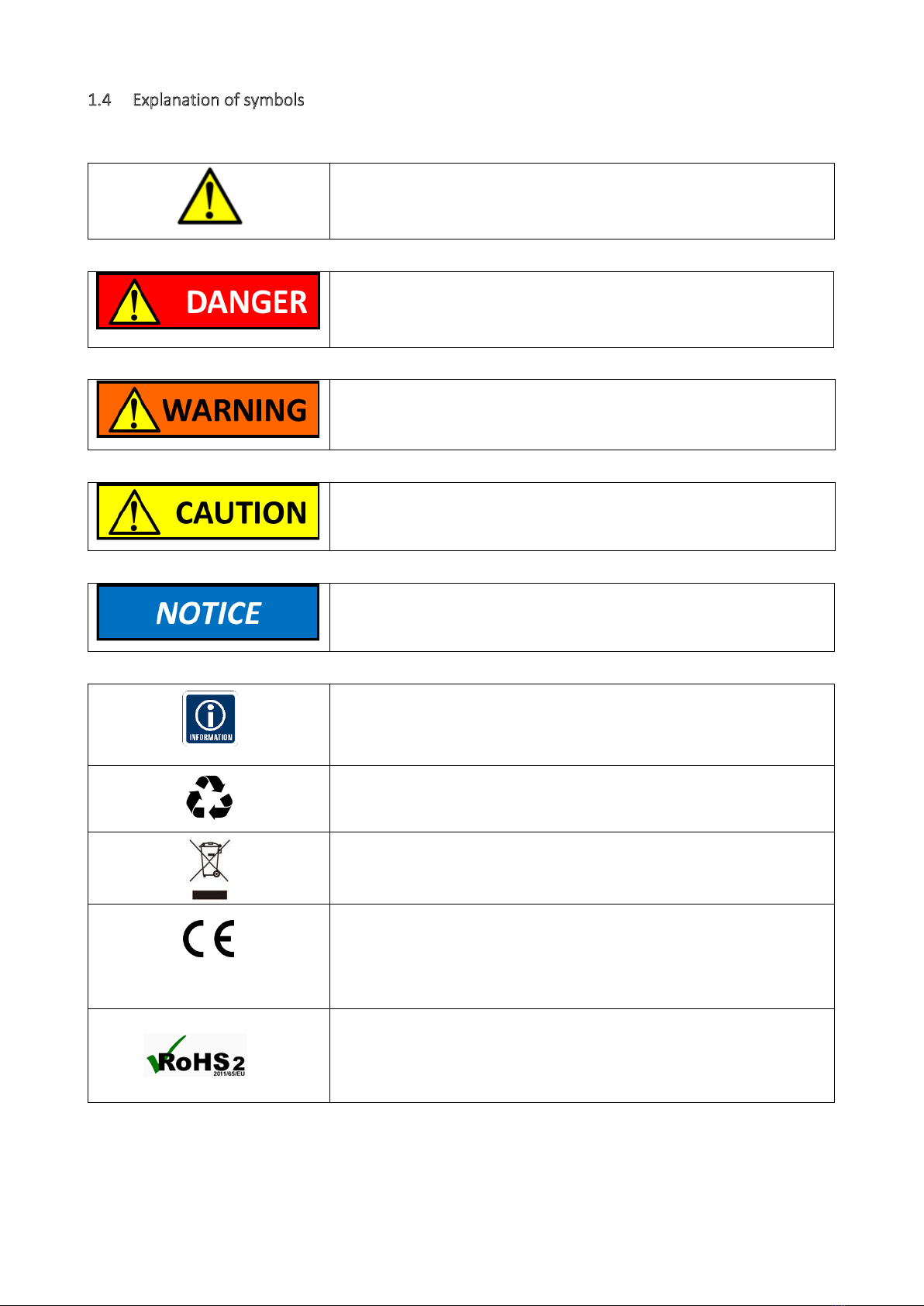
1.4 Explanation of symbols
The following symbols and signal words are used in this user manual, on the Dumo, or on the packaging.
This symbol indicates a hazard, a hazardous situation, a precaution to
avoid a hazard, a result of not avoiding a hazard or a combination of
them.
This signal symbol/word designates a hazard with a high degree of
risk, which will result in death or severe injury if not avoided.
This signal symbol/word designates a hazard with moderate risk,
which may result in death or severe injury if not avoided.
This signal symbol/word designates a hazard with low risk, which may
result in minor or moderate injury if not avoided.
This signal word warns of possible damage to property.
This symbol provides you with useful additional information on
handling and use.
Label for waste materials intended for recycling.
Electrical products may not be disposed of with household or other
garbage. Applicable in the European Union and other European
countries with separate collection systems of recyclable materials.
This instrument conforms to the following standards:
IEC 60079-0:2017
EN 60079-11:2012, EN 60079-31:2014
EN 61010-1:2001 Safety, LVD
EN 61326-1 A1 (1998) Electromagnetic Compatibility EMC
RoHOS2: Directive 2011/65/EU of the European Parliament and of the
Council of 8 June 2011 on the restriction of the use of certain
hazardous substances in electrical and electronic equipment Text with
EEA relevance.

Page 7 | 49
2General safety instructions
Only use the instrument as described in this user manual. Any other use is considered improper and may result
in damage to property or persons.
The manufacturer or vendor cannot be held liable for damages or injury or loss incurred through improper or
incorrect use.
These models are NOT UL/CSA or IECEX/ATEX certified and CANNOT be used in
explosion risk areas. Chose another model if required.
This product is intended for skilled technicians and trained and certified
operators. Make sure the Dumo is only operated by qualified personnel.
Electrical installation is only to be performed by qualified personnel.
Children may not install, operate, or maintain the Dumo. Make sure that children
do not play with the plastic wrapping. They may get caught in it when playing and
suffocate.
Do not modify, alter, or remove parts of the Dumo in any unforeseen way,
without prior written authorization from the Sintrol Customer Service
Department.
Do not use the instrument if it is damaged or if the power cord or plug is
defective.
For repairs always contact Sintrol authorized service partners. Do not perform
any mechanical or electrical repairs without prior consultation of Sintrol
authorized service partners
Only original Sintrol parts may be used for repairs. This device contains electrical
and mechanical parts which are essential for providing protection against sources
of danger.
3Intended use
The Dumo is exclusively designed to continuously measure the concentration of total suspended particles
(TSP) in ambient air under the conditions and limits outlined in this manual.
It is primarily meant for indoor operation in non-condensing conditions. (The instrument will recognize
droplets as particles and therefore cannot distinguish between water droplets and dust).
It is ideal for applications where any disruption in normal operation may result in an increase in particle
concentration in the workplace causing nuisance and harm to people or machinery. In areas requiring dust
extraction systems to lower particulate levels in the environment, Sintrol Dumo is the ideal complement to
monitor the efficiency of this dust removal process.
Only UL/CSA or IECEX/ATEX certified models, can be used in higher risk areas to detect abnormal levels of
potentially explosive dust concentrations.
SELLER HEREBY DISCLAIMS ANY AND ALL WARRANTIES AND REPRESENTATIONS (EXPRESS OR IMPLIED, ORAL
OR WRITTEN), INCLUDING ANY AND ALL IMPLIED WARRANTIES OF MERCHANTABILITY OR FITNESS FOR ANY
PURPOSE WHETHER OR NOT SELLER KNOWS, OR HAS REASON TO KNOW, HAS BEEN ADVISED, OR IS
OTHERWISE IN FACT AWARE OF ANY SUCH PURPOSE, WHETHER ALLEGED TO ARISE BY LAW, BY REASON OF
CUSTOM OR USAGE IN THE TRADE, OR BY COURSE OF DEALING OR PERFORMANCE.
PURCHASER UNDERSTANDS AND AGREES THAT IT SHALL BE PURCHASER’S SOLE RESPONSIBILITY TO ENSURE
THAT ALL PRODUCTS OBTAINED FROM SELLER SHALL ADHERE TO APPLICABLE LAWS, CODES AND STANDARDS
WITHIN THE TERRITORY OF USE. PURCHASER ABSOLVES AND HOLDS SELLER HARMLESS FOR ANY ALLEGED
VIOLATIONS OF SUCH LOCAL LAWS, CODES, AND STANDARDS WITHIN THE TERRITORY OF USE.

Page 8 | 49
Typical applications for the Dumo are:
Housekeeping applications
Control of unwanted dust accumulations and
general dust control
HVAC applications
Equipment safety
Employee hygiene,
To helps prevent explosions
To help the efficiency of dust removal systems
Welding fumes detection
Hazardous location monitoring
Typical industries in which the Dumo is used:
Steel and aluminum industries, foundries,
electroplating
Agriculture, food Industry, sugar and grain
mills, bakeries
Chemical and petrochemical industries,
fertilizer production, plastic production, color
and ink
Pulp and paper mills
Public facilities, subways
Mining, gravel pits, quarries
Power plants
Pharmaceutical industry
Wood and textile industries, cotton processing
Cement production, ceramic industry
Common dusts are:
Grains
Sugar
Coal
Cosmetics
Dyes
Ceramics
Textiles
Wood and paper
Soaps
Metals and metal oxides
Minerals
Ores
Cement
Plastics
Chemicals
Improper usage in CRITICAL APPLICATIONS,
such as but not limited to:
Worker protection, Health and Hygiene
Emissions monitoring
Process control
Explosions prevention
may lead to dangerous and hazardous situations and severe
consequential health impacts.
There are many factors which may influence the functionality of a dust measurement system.
These factors include but are not limited to the particle size of the dust, the dust material, design
and maintenance of ductwork as well as worker procedure and error. Therefore, the statements
made in Chapter3 Intended use, do not automatically imply the fitness of any of the Products for
a particular installation or application. This applies in particular when the dust monitor is only a
component of a whole system.
Sintrol recommends that all dust control system designs and functionality in the above listed
CRITICAL APPLICATIONS be reviewed and approved by an expert consultant who is responsible
for the integrity of the system design and compliance with locally accepted codes and
regulations.
Sintrol recommends using the instrument only within the limits set forth in Chapter 5.
Sintrol also recommends that proper maintenance procedures and work practices be followed to
maintain any dust control system in safe operating condition.
It is the responsibility of the customer to engage the services of qualified experts and certified
consultants in determining the suitability and application of the Sintrol products for any intended
use, in particular when the products are used as a part of systems used to monitor fire and
explosion risks and health or pollution related uses.

Page 9 | 49
4Dumo Overview
The instrument measures total suspended particles (TSP) in ambient air based on a signal generated from
moving particles. For parameterization and set up, Dumo can be accessed via USB with our DustTool software
(available free of charge on our website at http://www.sintrolproducts.com).
The instrument has a standard 4–20 mA output, which can easily be integrated into existing systems such as a
PLC in the control room. Dumo has “Alert” and “Alarm” signals which correspond to certain dust concentration
levels above the normal levels. By performing the Auto setup feature the normal dust level is determined and
the two “Alert” and “Alarm” levels are defined to factor five and factor 20 of that level. The instrument can
also be calibrated to show mg/m3by performing a reference measurement.
The instrument has a built-in fan, which draws in a steady and constant flow of ambient air through the
measuring chamber. Particulate flowing through the chamber will interact with the sensor rod causing a small
electrical charge to pass between the particulate and sensor. The small electric charges provide signals
monitored by the electronics. The generated signals are proportional to ambient dust levels.
The housing is made of aluminum. The measuring probe is stainless steel (316L) and the insulation material is
PTFE, commonly used as a high-performance thermoplastic).
Figure 1 Dumo structure and main parts

Page 10 | 49
4.1 Standard Scope of delivery
The standard scope of delivery of the Dumo includes:
One instrument
DustTool PC Software as a free download at www.sintrolproducts.com
X - Standard, O - Optional, -Blank- Not Available
Dumo
Dumo
RF
Rugged IP 65 rated Aluminum enclosure
X
X
Wall/DIN-rail mount bracket for easy installation in multiple angles and positions
O
O
Green, and red LED for status indication
X
X
Auto Setup function for efficient commissioning
X
X
Two solid state relays (SSR) to indicate dust alert and dust alarm
X
X
24 VDC power supply
X
X
USB interface for convenient connection during commissioning
X
X
DustTool PC software for parametrization and setup
X
X
Normalized during production to ensure identical instruments and quality
X
X
Linearized during production to standard test dust (Arizona Road Dust)
X
X
RS485 to communicate with Modbus RTU to your control system or with Sintrol
protocol to your PC and DustTool
XX
All possibly contaminated parts are easy to clean
X
X
Bright green illuminated 4- digit display and buttons for local setup and status
X
X
Isolated and active mA-output, to indicate the status ≥21 mA or ≤3.6 mA is used
X
X
Zero & span check with automatic drift compensation
X
X
Correlation possibility to read directly mg/m3
X
X
Long life, voltage-controlled fan with malfunction detection and early warning
X
X
Wireless network capability to avoid cabling cost and extensive installation
O
X
DustTool and DustLog compatible
X
X
Magnetic Switch to initiate Auto setup and fast parametrization
O
O
Parameter set selection and Auto Setup activation via Magnets
O
O
Page 11 | 49
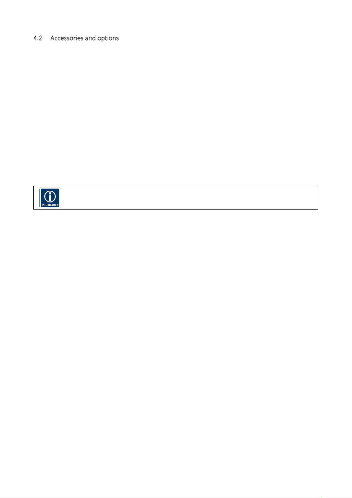
4.2 Accessories and options
According to the chosen Accessories and options, Dumo comes in the respective configuration.
Communication Accessories
RS485-to-USB converter
Network routers, wireless network routers and DustLog 8 reporting software.
These supplies have their own manuals which need to be read and followed.
Probe Coating
(Standard) No coating, stainless steel probe 316L
(Option) Teflon coating for wet processes in non-hazardous, non ATEX areas
Installation options
(Standard) Built-in mounting feet for wall, ceiling or tabletop mounting,
(Option) Wall/DIN-rail mount bracket
(Option) Adjustable installation arm
The standard, built-in mounting feet is the most suitable choice for installations with high
vibrations.
Power supply
Sintrol has thoroughly tested and can recommend the following power supplies to be used:
(Option) XP DNR120AS24 (DIN rail mount into cabinet)
(Option) Cool power CPS-24037C6 (Tabletop model)
If you would like to use a different power supply, it should meet the following specifications:
24VDC +-10%
Minimum 10W output power per Dumo which is connected to the power supply
Low output ripple, max 1% V p-p of output voltage

Page 12 | 49
4.3 Illustrations of components and dimensions: Dumo and Dumo RF
Figure 2 Dumo main dimensions
The built-in mounting feet can fit up to M6 fasteners.
4.4 Cable gland specification
Dumo has two M16x1,5 mm cable glands, capable of accepting cable diameters between 4,5 and 10 mm.
4.5 Terminal cover on the underside of the Dumo
On the underside of the device is a terminal cover with an O-ring. This is used to secure the device electronics
and the terminals.
The screw plug must be opened for electrical installation and should then be tightened and closed with 30Nm.
Terminal cover
35 mm or 60 mm
two-hole key
½” Ratchet handle
Page 13 | 49
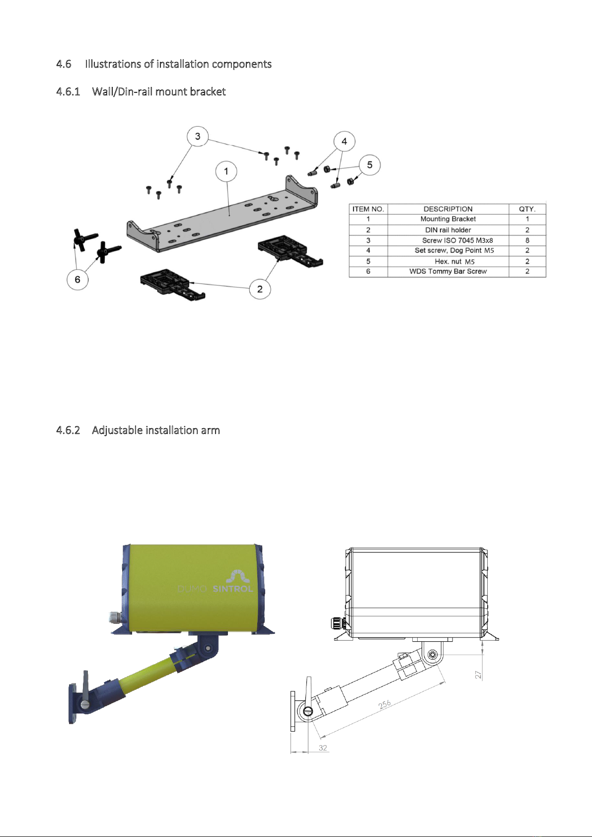
4.6 Illustrations of installation components
4.6.1 Wall/Din-rail mount bracket
Figure 3 Wall/Din-rail mounting bracket
The Dumo can be mounted onto a standard DIN-rail with the optional bracket. The bracket locks on to the
Dumo on various orientations, making the mounting easier in tight areas. This bracket can also be used to
mount the Dumo on to a ceiling with the display still being in the correct orientation.
4.6.2 Adjustable installation arm
The optional flexible installation arm allows the Dumo to be installed in a multitude of orientations and allows
for easy repositioning of the device. This option also leaves room to access the internal connection area while
the device is installed, making configuration changes easy and convenient. The arm has two adjustable joints
and the rotation between the joints can be adjusted as well. The Dumo can also be mounted in different
orientations in 90° steps.
Figure 4 Adjustable installation arm

Page 14 | 49
5Principle of operation, physical effects, and limitations
Sintrol dust monitors are based on a unique Inductive
Electrification technology. The measurement is based on particles
interacting with an isolated probe mounted into the duct or stack.
When moving particles pass nearby or hit the probe a signal is
induced. This signal is then processed through a series of Sintrol’s
advanced algorithms to filter out the noise and provide the most
accurate dust measurement output.
Classic triboelectric technology is based on the DC signal, which is
caused by particles contacting the sensor to transfer charges.
Compared to DC based measurements, the Inductive
Electrification technology is more sensitive and minimizes the
influence of sensor contamination, temperature drift and velocity
changes. By using the Inductive Electrification Technology it is possible to reach a detection limit as low as
0.01 mg/m3.
According to its position in the Triboelectric Table each material transfers a specific charge to the probe.
Inorganic, electro-conductive materials (metals) create the lowest signals, Inorganic dielectric materials
(cement, minerals) generate average signals, Organic dielectric materials (wood, flour) generate the highest
Signals. This charge is captured by our sensor and its signal level is proportional to the particle concentration.
As a unit for this signal level the Inductive Electrification Unit (IEU) is used.
The relation between Inductive Electrification Unit (IEU) and the mA output signal can be established by
performing the Auto Setup function.
The relation between Inductive Electrification Unit (IEU) and the dust concentration in mg/m3can be done by
calibrating the signal to a reference method e.g. to the results of a gravimetric sampling series.
5.1 Influence of particle material
The signals transmitted by different types of dust particles can vary greatly from one material to the other. For
example:
Inorganic electro-conductive materials (metals) create the lowest signals.
Inorganic dielectric materials (cement, minerals) generate average signals.
Organic dielectric materials (wood, flour) generate the highest signals.
This means that at the same concentration, different types of dusts generate different output signals. For
example, this behavior can be compared to the behavior of opacity monitors, which show a different result
depending on the color of the material: at the same concentration, white dust will show less opacity than black
dust.
The initial measuring values transmitted by this measuring technology are relative
measurements and the Dumo must not be relocated without a proper re-installation and
setup.
Figure 5 Inductive Electrification Technology

Page 15 | 49
5.2 Particle size
In terms of particle size, 425µm (40 mesh) is generally defined as the limiting size to classify a material as a
“dust.”
The minimum particle size which the Dumo is able to detect is 0.3 microns.
The best working range of the Dumo is between 1 and 200 microns.
5.3 Linearity, maximum concentrations, and calibration
The measuring range and the behavior of the Dumo depends on many factors, such as the dust material (as
explained in chapter 5.1 Influence of particle material), particle size, flow speed and installation location.
As an indication and averaging of different internal and external tests, Sintrol Products with Inductive
Electrification Technology show the following behavior over the measuring range:
Detection limit: 0.01 mg/m3
Linear range: from detection limit to several hundred mg/m3
Nonlinear range: from linear phase, up to several g/m3
Saturation: after nonlinear range
Figure 6: Illustration of un-calibrated measuring behavior
To measure higher concentrations than 200 mg/m3and it is critical to have a linear
behaviour we recommend performing reference measurements at the desired
concentration and add additional calibration points by using Sintrol
DustTool/calibration.
5.4 Influence of relative humidity RH %, condensation, and droplets in the measurement gas
Due to the working principle of the Dumo, the variation of relative humidity in the measurement gas only has
an insignificant effect on measurements as long as there is no condensation or droplets.
Condensate or droplets will be seen as dust particles and distort the measurement signal. A wrong signal will
be the consequence.
5.5 Influence of ambient temperature
As an indication and averaging of different internal and external tests, Sintrol Products with Inductive
Electrification Technology show very low influence of ambient temperature:

Page 16 | 49
Figure 7: Effect of Ambient Temperature
5.6 Influence of flow velocity at the Dumo
Since the Dumo is equipped with an internal sampling fan which provides a constant flow speed. The fan is
also monitored for changes in the performance to ensure a constant flow speed.
In situations with high winds (>5m/s), the surrounding airflow may affect the internal flow
speed of the Dumo and decrease the accuracy of the measurement.
Page 17 | 49
6Mechanical Installation
Critical installations in health or explosion-prone areas, as well as use in all dust control
systems, need to be reviewed and approved by an expert consultant who is responsible
for the integrity of the system design and compliance with locally accepted codes.
Critical installations are considered to be such installations where a failure may directly or
indirectly cause any damage to people or property.
Any information given or implied by Sintrol in any way regarding installation points, the overall
functionality of the system, or compatibility for a specific application are only suggestive and do
not replace approval by an expert consultant.
-Install the Dumo to the desired location with the mounting feet. Use up to M6 bolts or similarly sized
UNC/UNF fasteners. Optionally you can choose to buy the device with different mounting hardware,
including Wall/Din-rail mount bracket or the adjustable wall connecting system.
-For installations with the RF version, make sure that all the Dumos are oriented in the same direction
(antenna pointing in the same direction, vertical or horizontal) in order to avoid polarization losses in
the wireless communication.
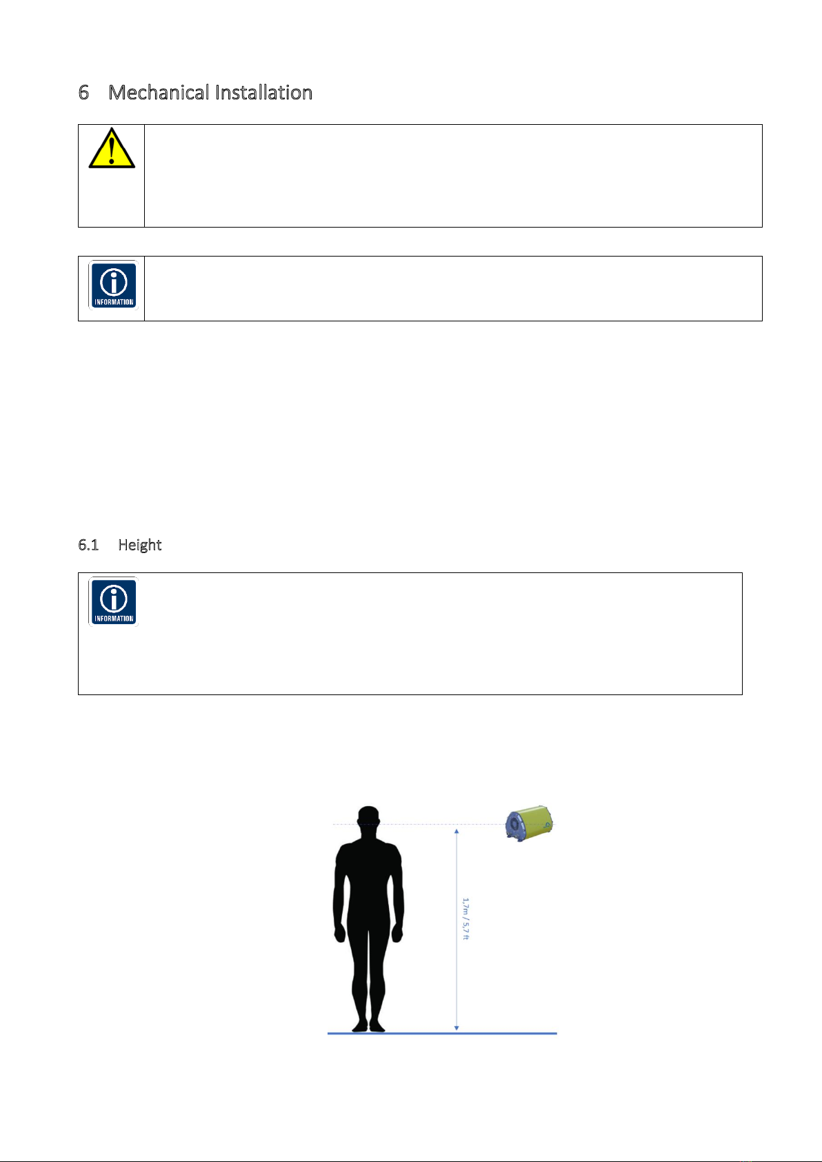
6.1 Height
In ambient air, larger airborne particles will generally collect and settle close to the
ground. Larger particles also represent the majority of the mass and volume of
airborne particles.
Because the Dumo measures Total Suspended Particles (TSP),it is reasonable to say
that it will show a higher signal closer to the ground as compared to an installation
point at some elevation higher than ground level.
-To survey certain machinery or a specific area of suspected dust emissions, place the Dumo as close as
possible to that location.
-To measure exposure to dust on humans, install the Dumo at a height relative to the respiratory tract
(see Figure 6).
Figure 8: Installation height

Page 18 | 49
6.2 Distances and grid layout
Dust always needs to move in form of airflows, winds, or clouds actively towards the
Dumo.
Dumo’s fan accelerates the gas towards the probe only once it is very close to the
duct inside the Dumo. The fan will NOT actively pull dust particles towards it. The
pulling effect of the fan is already negligible at less than ½ inch (1cm) from the Dumo.
The further away from the source of dust the Dumo is, the more diluted the
concentration of dust will be. This means that, while the dust concentration directly at
the source point may have already reached the minimum explosible concentration
(MEC), it may be well below this critical level further away.
The time delay between the appearance of the dust at its source point and the
measuring point will be longer, and the movement of the dust cloud slower, the
further away the two points are from each other.
Figure 9: Installation Point in terms of air flow
The more critical the installation is for worker safety, health, or explosion prevention, the
narrower the grid should be.
In case of an uncritical installation, where it can be assumed that the dust is fairly evenly
distributed and has time to spread, a grid of approximately (n) ~ 20 m / 65 ft. is recommended.
Figure 10: Installation Grid

Page 19 | 49
7Electrical Installation and Wiring
Pay attention when choosing the cable. It must meet and be installed according to all locally
applicable codes, and must be suitable for the environment it is going to be installed in.
Always use a shielded cable when possible. Make sure to connect the shield to a protective
earth potential at a single location.
Use a minimum of 0,3 mm2 or AWG 22 conductor size.
When connecting the cabling make sure to leave enough slack to allow for the device to be
removed from the process for cleaning without disconnecting the cables form the dust
monitor.
Risk of electric shock!
A faulty electrical installation, excessive line voltage, or incorrect
operation may result in an electric shock.
Always turn off and unplug the Dumo when you are not using it, when you intend to clean it, or in
the event of a malfunction.
Only connect the Dumo if the line voltage of the socket corresponds to the data on the rating plate.
Stand on an insulating pad and make it a habit to only use one hand when checking components.
Always work with another person in case an emergency should occur.
Disconnect power before checking the Dumo or performing maintenance.
Make sure all equipment is properly grounded.
Always wear safety glasses when working on the power supply.
Read and understand User Manual before installation.
7.1 Wire-To-Board Terminal Block (Screw)
The Dumo uses Wire-To-Board Terminal Blocks with the following specification:
Connection method: Screw thread M3, Tightening torque, min 0.5 Nm / max 0.6 Nm
Pitch: 5.08 mm
Connection direction: 55 °
Stripping length 8 mm
Conductor cross section solid min. 0.2 mm² / max. 4 mm²
Conductor cross section flexible min. 0.2 mm² max. 2.5 mm²
Conductor cross section AWG min. 24 / AWG max. 12

Page 20 | 49
7.2 Grounding and usage of grounded power supply
Risk of injury!
If the Dumo is not properly grounded, it may react to changes in the
ground potential and show false results, resulting in severe health
impacts to workers and/or a failure of the explosion prevention system.
Connect the grounding terminal next to the cable gland to stable ground potential.
The recommended grounding is where the Dumo external grounding terminal is connected to a
nearby grounding strip.
Telltale signs of improper grounding include base values of over 3000 in clean office air or
noticeable reaction to touching the Dumo series enclosure. Note that sub-par quality power
sources might also induce such effects.
7.1 Connecting the voltage supply
Figure 11: Connecting power input
Connect a 24 VDC power supply to the device in the internal connection area. Pay close attention to the
polarity of the power input.
In case of wrong polarity, the devices will not start up, however the device will not be harmed
or broken.
This manual suits for next models
1
Table of contents


