Prodigit 3110 Series User manual

3110 Series
Plug-In Electronic
Load Operation manual
S/N:900311002 REV:A

Material Contents Declaration
(材料含量宣称)
(Part Name)
零件名称
Hazardous Substance (
有毒有害物质或元素
)
铅
(Pb)
汞
(Hg)
镉
(Cd)
六价铬
(Cr6+)
多溴联
苯(PBB)
多溴二苯醚
(PBDE)
PCBA
(印刷电路装配件)
x
○
x
○
○
○
Electrical part not on
PCBA’s
未在
PCBA
上的电子零件
x
○
x
○
○
○
Metal parts
金属零件
○
○
○
x
○
○
Plastic parts
塑料零件
○
○
○
○
x
x
Wiring
电线
x
○
○
○
○
○
Package
封装
x
○
○
○
○
○
对销售之日的所售产品
,
本表显示
, PRODIGIT
供应链的电子信息产品可能包含这些物质。注意
:
在所售产品中可能
会也可能不会含有所有所列的部件。This table shows where these substances may be found in the supply chain
of Prodigit electronic information products, as of the date of sale of the enclosed product. Note that some of the
component types listed above may or may not be a part of the enclosed product. ○:表示该有毒有害物质在该部
件所有均质材料中的含量均在SJ/T 11363-2006 标准规定的限量要求以下。○:Indicates that the concentration of
the hazardous substance in all homogeneous materials in the parts is below the relevant threshold of the SJ/T
113632006 standard. ×:表示该有毒有害物质至少在该部件的某一均质材料中的含量超出SJ/T 11363-2006 标准
规定的限量要求。×:Indicates that the concentration of the hazardous substance of at least one of all
homogeneous materials in the parts is above the relevant threshold of the SJ/T 11363-2006 standard.
Note(注释):
1.Prodigit has not fully transitioned to lead-free solder assembly at this moment;However, most of the
components used are RoHS compliant.
(此刻,Prodigit 并非完全过渡到无铅焊料组装;但是大部份的元器件一至于RoHS的规定。)
2. The product is labeled with an environment-friendly usage period in years.
The marked period is assumed under the operating environment specified in the product specifications.
(产品标注了环境友好的使用期限制(年)。所标注的环境使用期限假定是在此产品定义的使用环境之下。)
Example of a marking for a 10 year period:
(例如此标制环境使用期限为10年)

SAFETY SUMMARY
The following general safety precautions must be observed during all phases of operation, service,
and repair of this instrument. Failure to comply with these precautions or with specific warnings
elsewhere in this manual violates safety standards of design, manufacture, and intended use of the
instrument. PRODIGIT assumes no liability for the customer's failure to comply with these
requirements.
GENERAL
This product is a Safety Class 1 instrument (provided with a protective earth terminal). The protective
features of this product may be impaired if it is used in a manner not specified in the operation
instructions.
ENVIRONMENTAL CONDITIONS
This instrument is intended for indoor use in an installation category I, pollution degree 2 environments.
It is designed to operate at a maximum relative humidity of 80% and at altitudes of up to 2000 meters.
Refer to the specifications tables for the ac mains voltage requirements and ambient operating
temperature range.
BEFORE APPLYING POWER
Verify that the product is set to match the available line voltage and the correct fuse is installed.
GROUND THE INSTRUMENT
This product is a Safety Class 1 instrument (provided with a protective earth terminal). To minimize
shock hazard, the instrument chassis and cabinet must be connected to an electrical ground. The
instrument must be connected to the ac power supply mains through a three conductor
power cable, with the third wire firmly connected to an electrical ground (safety ground) at the power
outlet. Any interruption of the protective (grounding) conductor or disconnection of the protective earth
terminal will cause a potential shock hazard that could result in personal injury.
FUSES
Only fuses with the required rated current, voltage, and specified type (normal blow, time delay, etc.)
should be used. Do not use repaired
Fuses or short circuited fuse holder. To do so could cause a shock or fire hazard.
DO NOT OPERATE IN AN EXPLOSIVE ATMOSPHERE.
Do not operate the instrument in the presence of flammable gases or fumes.
KEEP AWAY FROM LIVE CIRCUITS.
Operating personnel must not remove instrument covers. Component replacement and internal
adjustments must be made by qualified service personnel. Do not replace components with power
cable connected. Under certain conditions, dangerous voltages may exist even with the power cable
removed. To avoid injuries, always disconnect power, discharge circuits and remove external voltage
sources before touching components.
DO NOT SERVICE OR ADJUST ALONE.
Do not attempt internal service or adjustment unless another person, capable of rendering first aid and
resuscitation, is present.
DO NOT EXCEED INPUT RATINGS.
This instrument may be equipped with a line filter to reduce electromagnetic interference and must be
connected to a properly grounded receptacle to minimize electric shock hazard. Operation at line
voltages or frequencies in excess of those stated on the data plate may cause leakage currents in
excess of 5.0 mA peak.
DO NOT SUBSTITUTE PARTS OR MODIFY INSTRUMENT.
Because of the danger of introducing additional hazards, do not install substitute parts or perform any
unauthorized modification to the instrument. Return the instrument to a PRODIGIT ELECTRONICS
Sales and Service Office for service and repair to ensure that safety features
are maintained.
Instruments which appear damaged or defective should be made inoperative and secured against
unintended operation until they can be repaired by qualified service personnel.
DECLARATION OF CONFORMITY
Company Name: PRODIGIT ELECTRONICS CO., LTD
Address:8F, No.88, Baojhong Rd., Sindian District, New Taipei City, Taiwan.
Declares under sole responsibility that the product as originally delivered
Product Names:DC Electronic Loads
Model Numbers:3110, 3111, 3114, 3117, 3119
(And other customized products based upon the above)
Product Options:
Safety and EMC Information:
This declaration covers all options and customized products based on the above products.
Complies with the essential requirements of the Low Voltage Directive 2014/35/EU and the EMC
Directive 2014/30/EUand carries the CE Marking accordingly.
Safety standard:
Safety standards following:
IEC 61010-1:2010 / EN 61010-1:2010
EMC standard:
EN 61326-1:2012
EN 55011:2009+A1:2010
EN 61000-3-2:2006+A1:2009+A2:2009
EN 61000-3-3:2008
EN 61000-4-2:2009
EN 61000-4-3:2006+A1:2008+A2:2010
EN 61000-4-4:2004+A1:2010
EN 61000-4-5:2006
EN 61000-4-6:2009
EN 61000-4-8:2010
EN 61000-4-11:2004
9, 18, 2019
Date
The holder of the verification is authorized to use this verification in connection with the EC declaration
of conformity according to the Directives. The CE marking may only be used if all releveant and
effective EC Directives are complied with. Together with the manufacturer’s own documented
production control, The manufacturer (or his European authorized representative) can in his EC
Declaration of Conformity Verify compliance with the directives.
SAFETY SYMBOLS
Direct current (DC)
Alternating current (AC)
Both direct and alternating
Three-phase alternating current
Off (Supply)
On (Supply)
Protective earth (ground)
Caution!Refer to this manual before using the meter.
Caution, risk of electric shock
CAT IV – Is for measurements performed at the source of the low-voltage
installation.
CAT III – Is for measurements performed in the building installation.
CAT II – Is for measurements performed on circuits directly connected to the low-
voltage installation.
CAT I – Is for measurements performed on circuits not directly connected to Mains.
Fuse

3110 series module load operation manual
Table of Contents
Chapter 1 Introduction ···························································································1
1-1 General description ·······················································································1
1-2 Features ·····································································································7
1-3 Standard Accessories····················································································7
1-4 Specifications ······························································································9
Chapter 2 Installation··························································································· 10
2-1 Check line voltage ······················································································ 10
2-2 Input Fuse································································································· 11
2-3 Environmental requirements ········································································· 12
2-4 Observe the International Electrical Symbol listed below. ···································· 12
2-5 Cleaning ··································································································· 12
2-6 Power Up·································································································· 13
2-7 RS232 & USB Interface ··············································································· 13
2-8 Load wire inductance··················································································· 14
Chapter 3 Operation ···························································································· 17
3-1. Dimension································································································· 17
3-2. Front panel LCD description·········································································· 19
3-3. Initial setting of 3110 series load module ························································· 50
3-4. Input terminal and wire consideration ······························································ 53
3-5. . Protection features ···················································································· 54
Chapter 4 Communication Interface programming operation ········································ 56
4-1. Introduction ······························································································· 56
4-2. RS232 Set-up ···························································································· 56
4-3. 3110 series Communication Interface programming command list 1 ······················ 58
4-4. Communication Interface programming command list 2 ······································ 62
4-5. The description of abbreviation ······································································ 66
4-6. Communication Interface programming command syntax description ···················· 66
4-7. Communication Interface programming command description ······························ 67
Chapter 5 Applications ························································································· 78
5-1. Local sense connections ·············································································· 78
5-2. Remote sense connections··········································································· 79
5-3. Constant Current mode application································································· 80
5-4. Constant Resistance mode application···························································· 83
5-5. Constant Voltage mode application ································································ 86
5-6. Constant Power mode application ·································································· 88
5-7. Zero-Volt loading application ········································································· 91
5-8. 3110 series electronic load OCP, OPP, SHORT operation flow Chart ···················· 92
5-9. Power Supply OCP testing ··········································································· 93
5-10. Power Supply OPP testing········································································· 95
5-11. SHORT testing ························································································ 96

Figures
Fig 1-1 3110 80V/50A/250W power contour································································2
Fig 1-2 3111 80V/70A/350W power contour································································2
Fig 1-3 3114 500V/15A/350W power contour······························································2
Fig 1-4 3117 80V/140A/700W power contour ······························································3
Fig 1-5 3119 500V/30A/700W power contour ······························································3
Fig 1-6 Constant Current mode················································································3
Fig 1-7 Constant Resistance mode ···········································································4
Fig 1-8 Constant Voltage mode················································································4
Fig 1-9 Constant Power mode ·················································································4
Fig 1-10 Dynamic Wave form ··················································································5
Fig 1-11 Rise Time Transition Limitation ····································································6
Fig 2-1 SET OF SWITCH ····················································································· 10
Fig 2-2 FUSE RECEPTACLE ················································································ 11
Fig 2-3 Waveform example: Generate unstable oscillation ··········································· 15
Fig 2-4 Length of wiring························································································ 16
Fig 3-1 Front panel of 3110 Series LCD ··································································· 19
Fig 3-2 typical connection of 3110 series load module ················································ 44
Fig 3-3 An equivalent circuit in terms of the current monitor ········································· 45
Fig 3-4 (Correct) Connections to an oscilloscope ······················································· 46
Fig 3-5 (Wrong) Connections to an oscilloscope ························································ 46
Fig 3-6 Hook Terminal Y type large size terminal connections ······································ 53
Fig 5-1 Local voltage sense connections·································································· 78
Fig 5-2 Remote voltage sense connections ······························································ 79
Fig 5-3 constant CURRENT mode application··························································· 80
Fig 5-4 Dynamic load current with independent programmed Rise/Fall slew rate ·············· 81
Fig 5-5 Constant Resistance mode Application·························································· 84
Fig 5-6 Constant Voltage mode application······························································· 86
Fig 5-7 CONSTANT POWER MODE APPLICATION ·················································· 89
Fig 5-8 Zero-Volt loading connection······································································· 91
Fig 5-9 3110 series electronic load OCP, OPP, SHORT operation flow chart ··················· 92
Tables
Table 1-1 3110 Series Specification··········································································9
Table 3-1 3110 initialize ······················································································· 50
Table 3-2 3111 initialize ······················································································· 51
Table 3-3 3114 initialize ······················································································· 51
Table 3-4 3117 initialize ······················································································· 52
Table 3-5 3119 initialize ······················································································· 52
Table 3-6 Stranded Copper Wire Ampere Capacity ···················································· 54
Table 4-1 Communication Interface programming Setting command summary················· 58
Table 4-2 Communication Interface programming query command summary··················· 59
Table 4-3 Communication Interface programming limit command summary····················· 60
Table 4-4 STAGE COMMAND SUMMARY······························································· 61
Table 4-5 SYSTEM COMMAND SUMMARY····························································· 61
Table 4-6 MEASURE COMMAND SUMMARY ·························································· 61
Table 4-1B Communication Interface programming Setting command summary··············· 62
Table 4-2B Communication Interface programming query command summary················· 63
Table 4-3B Communication Interface programming limit command summary··················· 64
Table 4-4B STAGE COMMAND SUMMARY····························································· 65

Table 4-5B SYSTEM COMMAND SUMMARY··························································· 65
Table 4-6B MEASURE COMMAND SUMMARY ························································ 65
Table 4-7 COMMAND TERMINATOR ····································································· 66
Table 4-8 module for each series ··········································································· 73
Table 4-9 register of PROT status ·········································································· 75
Table 4-10 MODEL NUMBER ··············································································· 76

3110 Series Operation Manual 1
Chapter 1 Introduction
1-1 General description
More and more electronic products, such as mobile phones, laptops, tablet chargers, mobile
power supplies, wireless chargers, electric hand tool chargers, etc., are currently using a single
input voltage. In response to this trend, Electronics introduced the single-machine 3110 series
of five electronic loads, including 80V and 500V, 350W and 700W four loads, and a 250W / 80V
/ 50A low wattage load to meet the needs of various tests on the market. .
3110 series electronic load continues the functions of various electronic load modes, including
constant current, constant resistance, constant voltage, and constant power, dynamic and
short-circuits mode, high-precision 5bit voltage, current, and power meter display
simultaneously, full range RS232 and USB interfaces are standard.
For fast-charging mobile phones and mobile power supplies, the 3110 Series electronic load
can be used with the 9922 or 9922-R Fast Charge Controller to test and validate USB-C and
QC 2.0, QC 3.0 and other specifications. In addition, it also includes various complete
performance tests for battery CC, CP, timed discharge, etc., and Surge function for simulating
electronic product startup overcurrent and hot plugging instantaneous current.
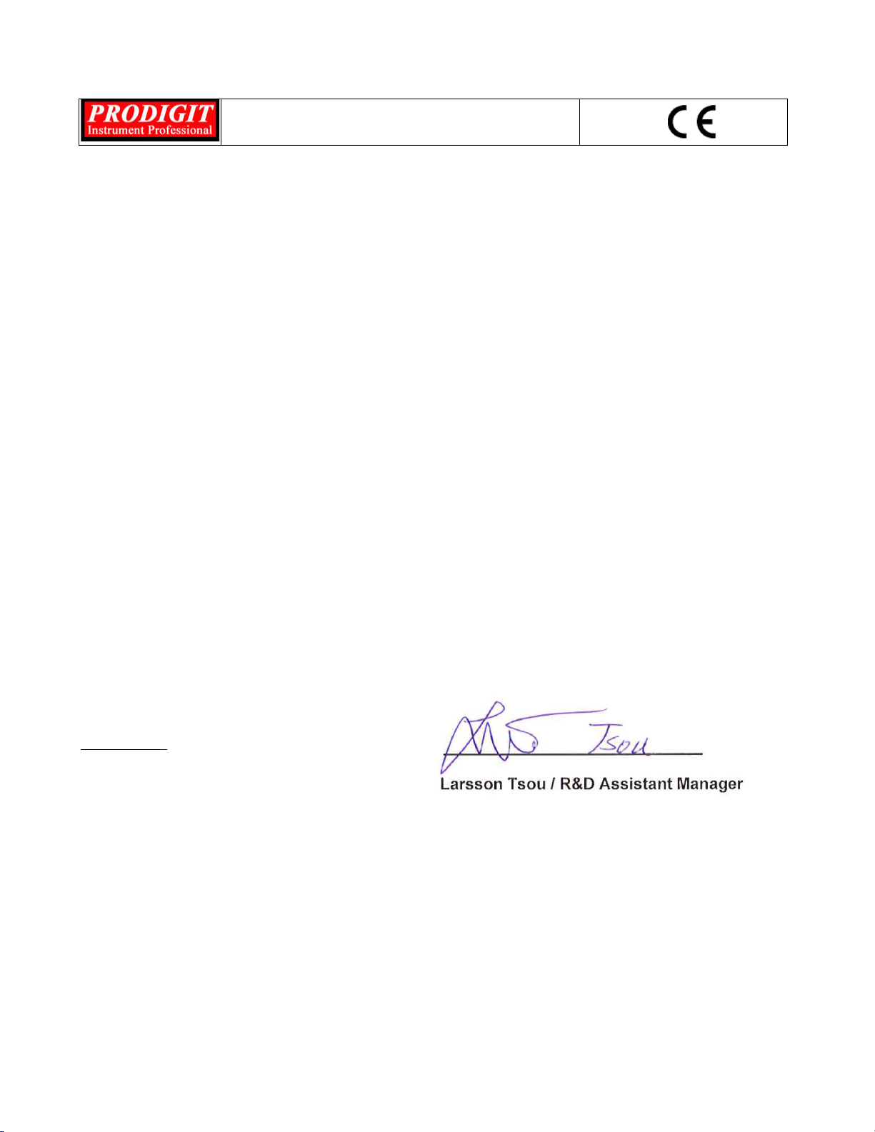
Each load module is capable of sinking a wide range of voltage and current values. The load
modules are limited by the maximum power they can sink. For example the 3110 can sink up to
50A and 80Vdc at a maximum of 250W. So if the maximum voltage of 80Vdc is present at the
load’s input terminals a maximum load current of 3.125A is possible. Conversely if the 3110 is
required to sink 50A the voltage must be limited to 5V.
The power contour of each load module in the 3110 series is shown in Fig 1-1, to 1-5.
2PRODIGIT
80V
5V
1V
50A3.125A
250W
Power Curve
Current
Voltage
Fig 1-1 3110 80V/50A/250W power contour
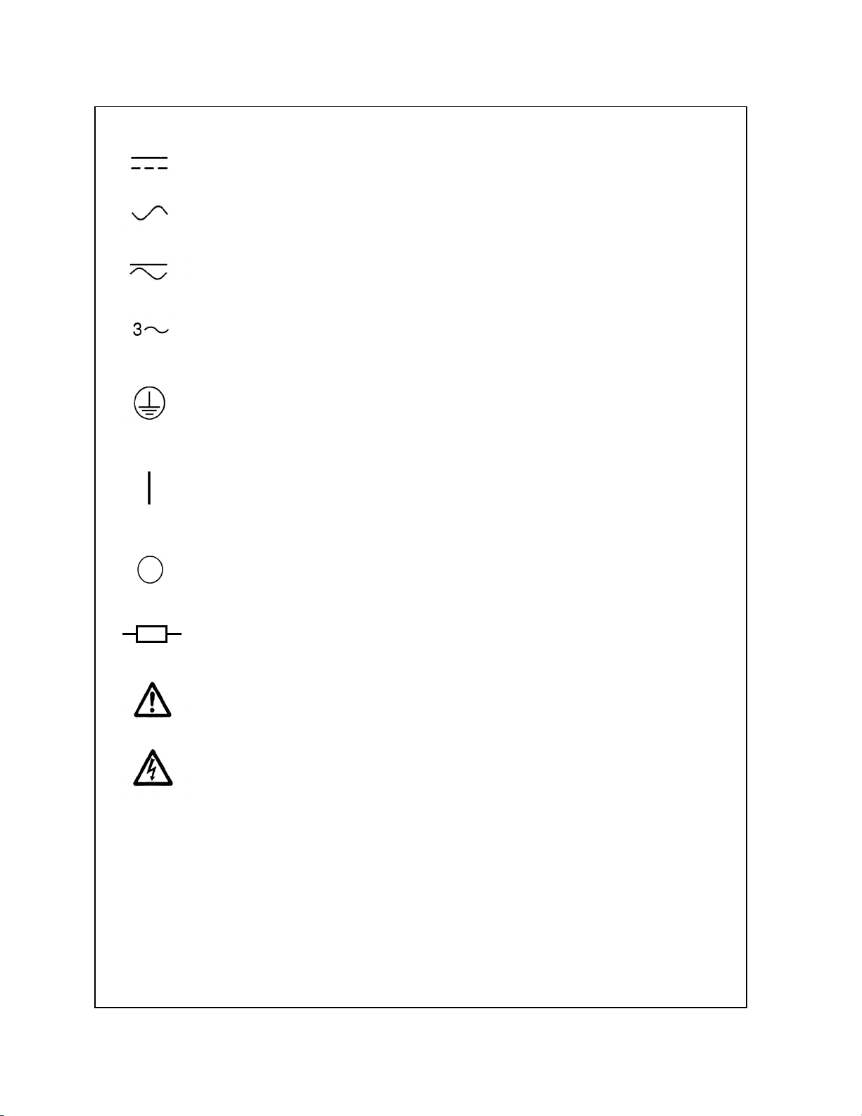
80V
5V
1.2V
70A4.375A
350W
Power Curve
Current
Voltage
Fig 1-2 3111 80V/70A/350W power contour
500V
23.3V
6V
15A0.7A
350W
Power Curve
Current
Voltage
Fig 1-3 3114 500V/15A/350W power contour
3110 Series Operation Manual 3
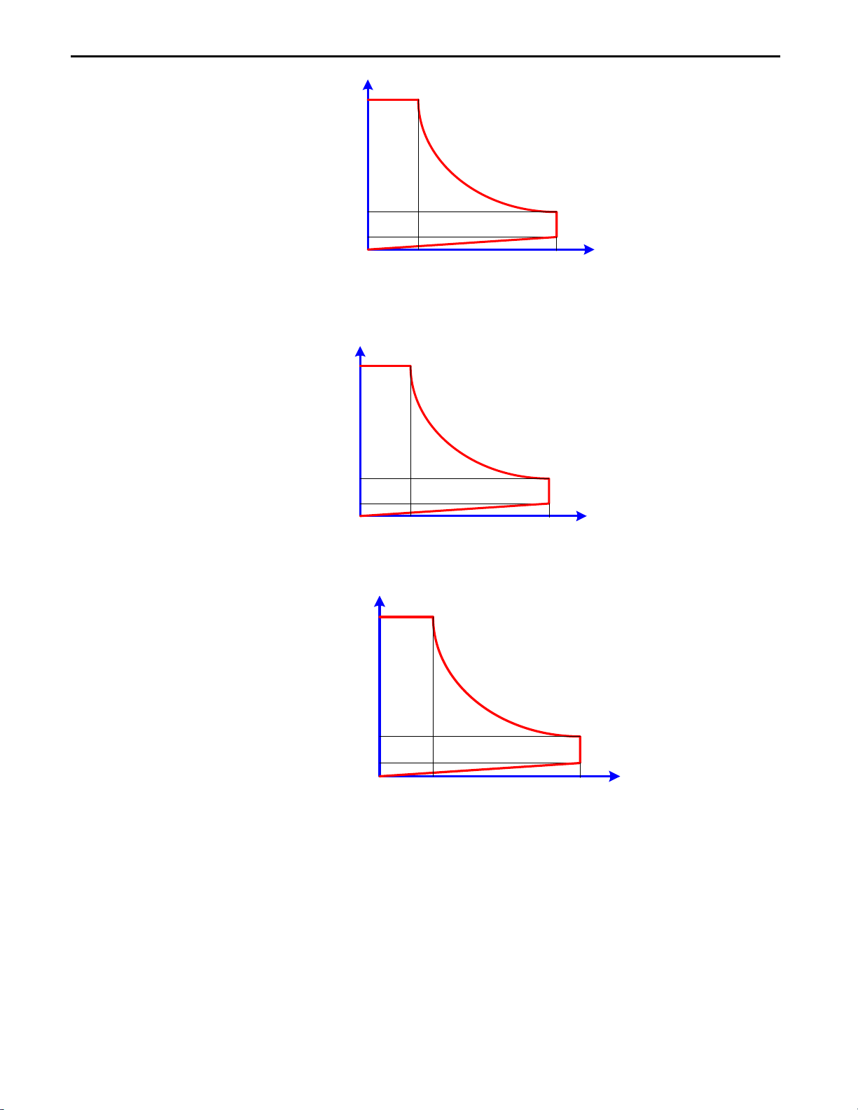
80V
25V
0.9V
140A8.75A
700W
Power Curve
Current
Voltage
Fig 1-4 3117 80V/140A/700W power contour
500V
23.33V
3V
30A1.4A
700W
Power Curve
Current
Voltage
Fig 1-5 3119 500V/30A/700W power contour
The 3110 series of electronic load modules feature 4 operating modes. These are
Constant Current (CC) mode, Constant Resistance (CR) mode, Constant Voltage (CV)
mode, and Constant Power (CP) mode.
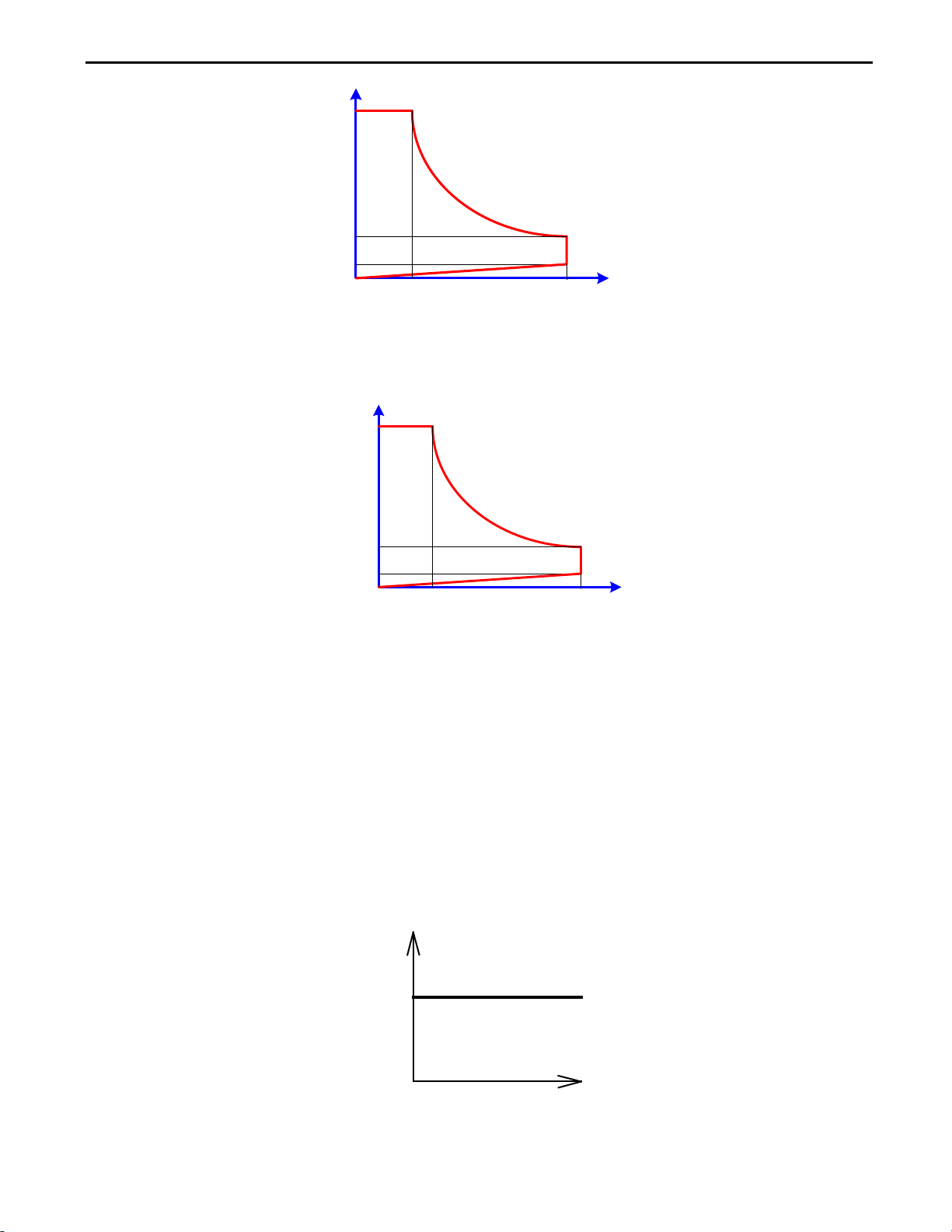
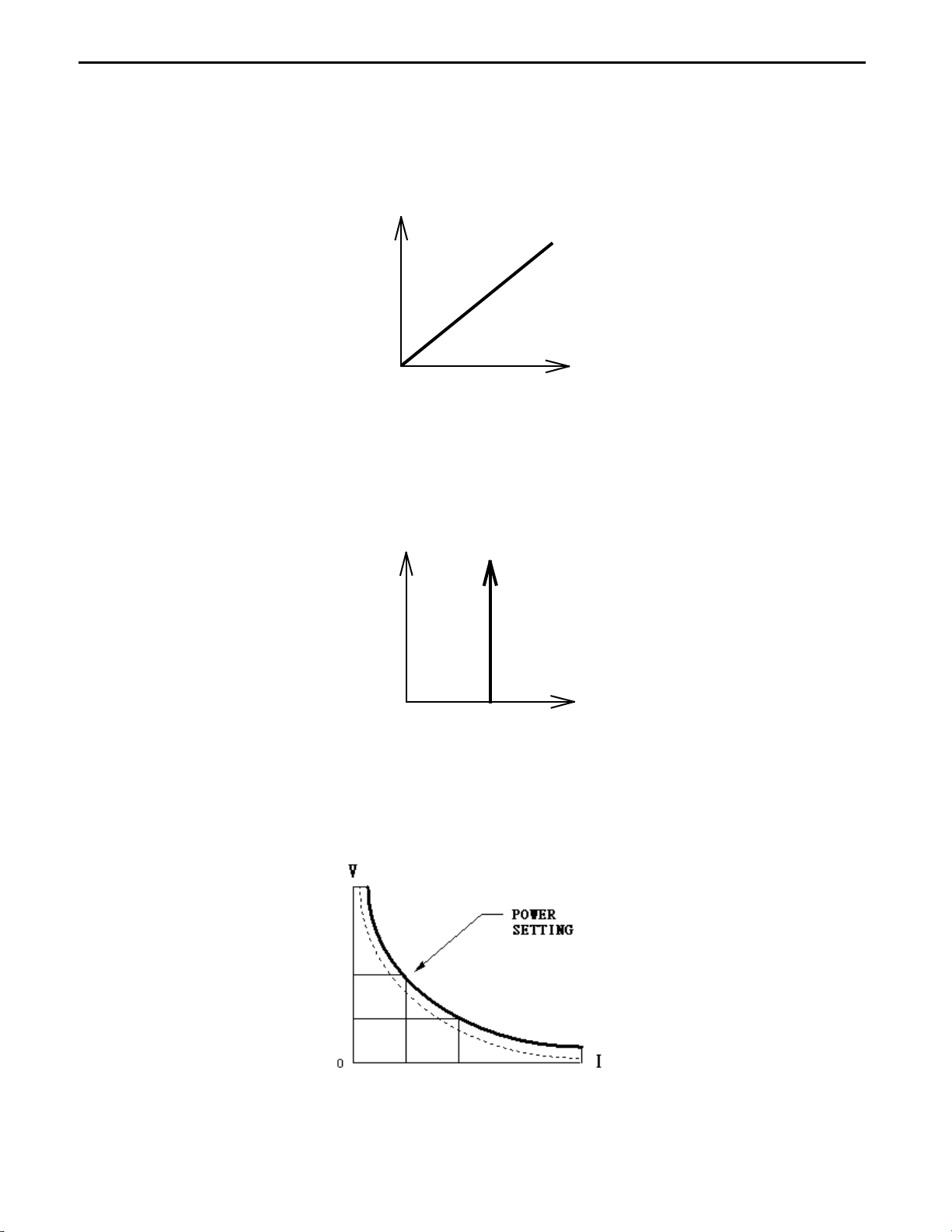
1.1.1. CC Mode
With the operating mode of Constant Current, the 3110 series electronic load will sink a
current in accordance with the programmed value regardless of the input voltage (see
Fig.1-6).
I
V
CC
LOAD
CURRENT
CURRENT SETTING
INPUT VOLTAGE
Fig 1-6 Constant Current mode
4PRODIGIT
1.1.2. CR Mode:
At Constant Resistance mode, the 3110 series Electronic Load will sink a current linearly
proportional to the load input voltage in accordance with the programmed resistance setting
(see Fig 1-7).
I
V
LOAD
CURRENT
INPUT VOLTAGE
RESISTANCE
SETTING
Fig 1-7 Constant Resistance mode
1.1.3. CV Mode:
At Constant Voltage mode, the 3110 series Electronic Load will attempt to sink enough
current until the load input voltage reaches the programmed value (see Fig 1-8).
I
V
LOAD
CURRENT
INPUT VOLTAGE
VOLTAGE
SETTING
Fig 1-8 Constant Voltage mode
1.1.4. CP Mode:
At Constant Power mode, the 3110 series Electronic Load will attempt to sink load power
(load voltage * load current) in accordance with the programmed power. (See Fig 1-9).
Fig 1-9 Constant Power mode

3110 Series Operation Manual 5
1.1.5. Dynamic Waveform Definition
Along with static operation the 3110 load modules are built with a Dynamic mode for
operation in Constant Current (CC), Constant Resistance (CR) or Constant Power (CP).
This allows the test engineer to simulate real world pulsing loads or implement a load profile
that varies with time.
A dynamic waveform can be programmed from the front panel of the 3110 load module. The
user would first set a High and low value of load current using the Level button. The
Dynamic Setting then allows for the rise and fall time between these 2 current values to be
adjusted. The time period that the waveform is high (Thigh) along with the time period that
the waveform is low (Tlow) can also be set.
The dynamic waveform is illustrated below in Fig 1-10.
I
V
LOAD
CURRENT
RISE
SLEW RATE
HIGH LOAD
LOAD
LOW LOAD
LEVEL
T
HIGH
T
LOW
FALL SLEW RATE
Fig 1-10 Dynamic Wave form
The dynamic waveform can also be set up via the optional computer interface. Dynamic
waveform settings made from the front panel of the load module can also be saved in the
memory of the mainframe. For the store/recall procedure and the computer command set
please refer to the relevant operating manual for the 3300G/3302G/3305G mainframes.
Further dynamic waveform definitions are:
•The period of dynamic waveform is Thigh + Tlow
•The dynamic frequency = 1 /( Thigh + Tlow )
•The duty cycle = Thigh / ( Thigh + Tlow )
1.1.6. Slew Rate
Slew rate is defined as the change in current or voltage over time. A programmable slew
rate allows for a controlled transition from one load setting to another. It can be used to
minimize induced voltage drops on inductive power wiring, or to control induced transients
on a test device (such as would occur during power supply transient response testing).
In cases where the transition from one setting to another is large, the actual transition time
can be calculated by dividing the voltage or current transition by the slew rate. The actual
transition time is defined as the time required for the input to change from 10% to 90% or
from 90% to 10% of the programmed excursion.

6PRODIGIT
In cases where the transition from one setting to another is small, the small signal
bandwidth (of the load) limits the minimum transition time for all programmable slew rates.
Because of this limitation, the actual transition time is longer than the expected time based
on the slew rate, as shown in Figure 1-11
Slew Rate
Expected time
Actual Time
10 %
0 %
100 %
90 %
Voltage (Volts)
Or
Current (Amps)
Slew Rate
Time
mS
Fig 1-11 Rise Time Transition Limitation
Therefore, both minimum transition time and slew rate must be considered when
determining the actual transition time.
Following detail description is exclude in operation manual.
The minimum transition time for a given slew rate as about a 30% or greater load change,
The slew rate increases from the minimum transition time to the Maximum transition time at
a 100% load change. The actual transition time will be either the minimum transition time,
Or the total slew time (transition divided by slew rate), whichever is longer.
EX: 3110 80V/50A/250W (CCH - CCL >50.4Ax 30%)
Use the following formula to calculate the minimum transition time for a given slew rate
Min transition time=18A/slew rate (in amps/second).
7.56uS (15.12A/2) x 0.8(10%~90%) =6.048uS
Use the following formula to calculate the maximum transition time for a given slew rate
Max transition time=60/slew rate (in amps/second).
25.2uS (50.4A/2) x 0.8(10~90%) = 20.16uS
EX. CCH=10.08A, CCL=0A Slew Rate =2A/uS, the expected time is 128uS but the actual
Transition Time will be limited to 144uS
5.04uS (10.08A/2) x 0.8(10%~90%) = 4.032uS
3110 Series Operation Manual 7
1-2 Features
The main features of the 3110 series of load modules are highlighted below.
•5 digital V / A / W Meter.
•High-speed measurement and communication transmission.
•V.A.W. values can be displayed simultaneously.
•Large LCD Display、setting values can be adjusted by rotary knob or push button.
•Short, OCP, OPP, Battery and Surge test function.
•Battery test function with stop condition: Vbatt, Discharge capacity and discharge time.
•Surge test with boot-on inrush simulation and hot-swap simulation.
•Flexible CC. CR, CV, CP, Dynamic and Short operation modes.
•SHORT time setting and SHORT_VH, SHORT_VL setting function.
•Protections against V, I, W, and °C.
•Voltage meter display the polarity positive(” +”)or negative(” -”)is selectable.
•Interface : RS232、USB
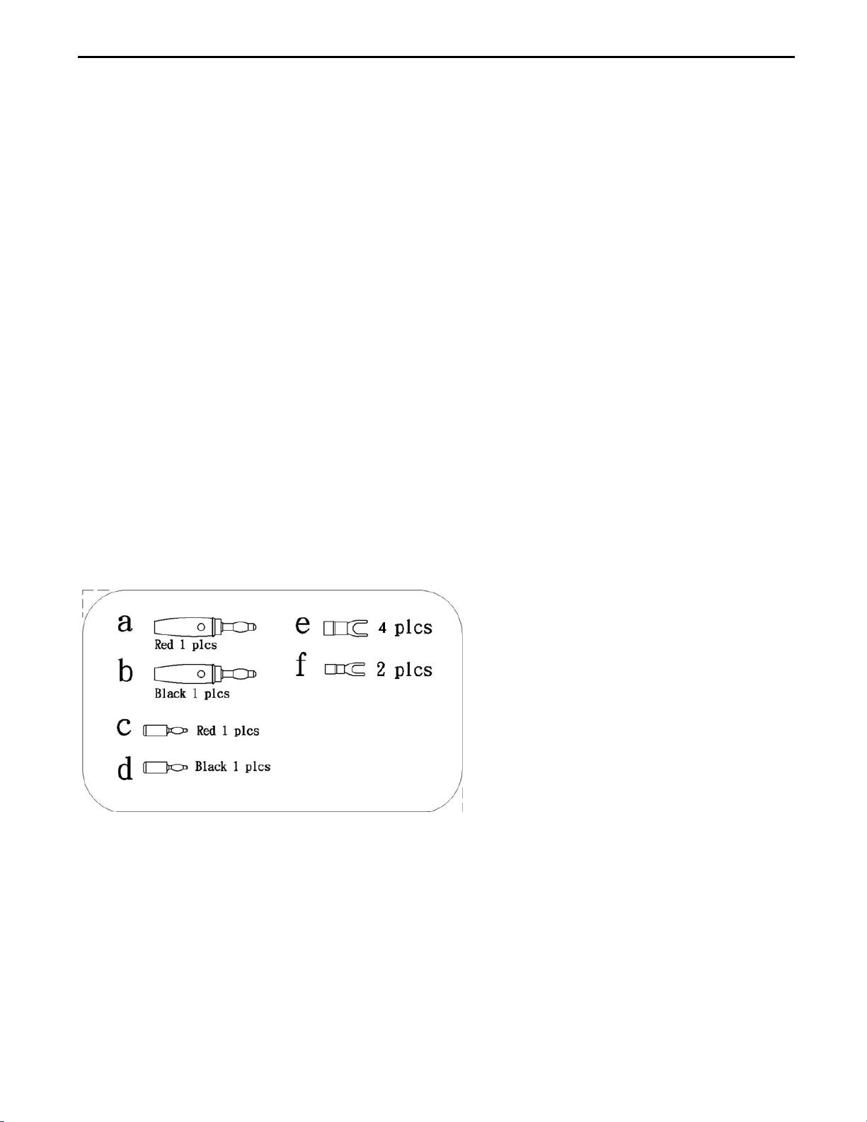
1-3 Standard Accessories
a 4mm Banana Plug (Red) 1 PC
b 4mm Banana Plug (Black) 1 PC
c 2mm Banana Plug (Red) 1 PC
d 2mm Banana Plug (Black) 1 PC
e Hook Terminal Y type Large size terminal 4 PCS
f Hook Terminal Y type small size terminal 2 PCS
g BNC Cable 1 PC
h 3110 series operation manual 1 PC
8PRODIGIT
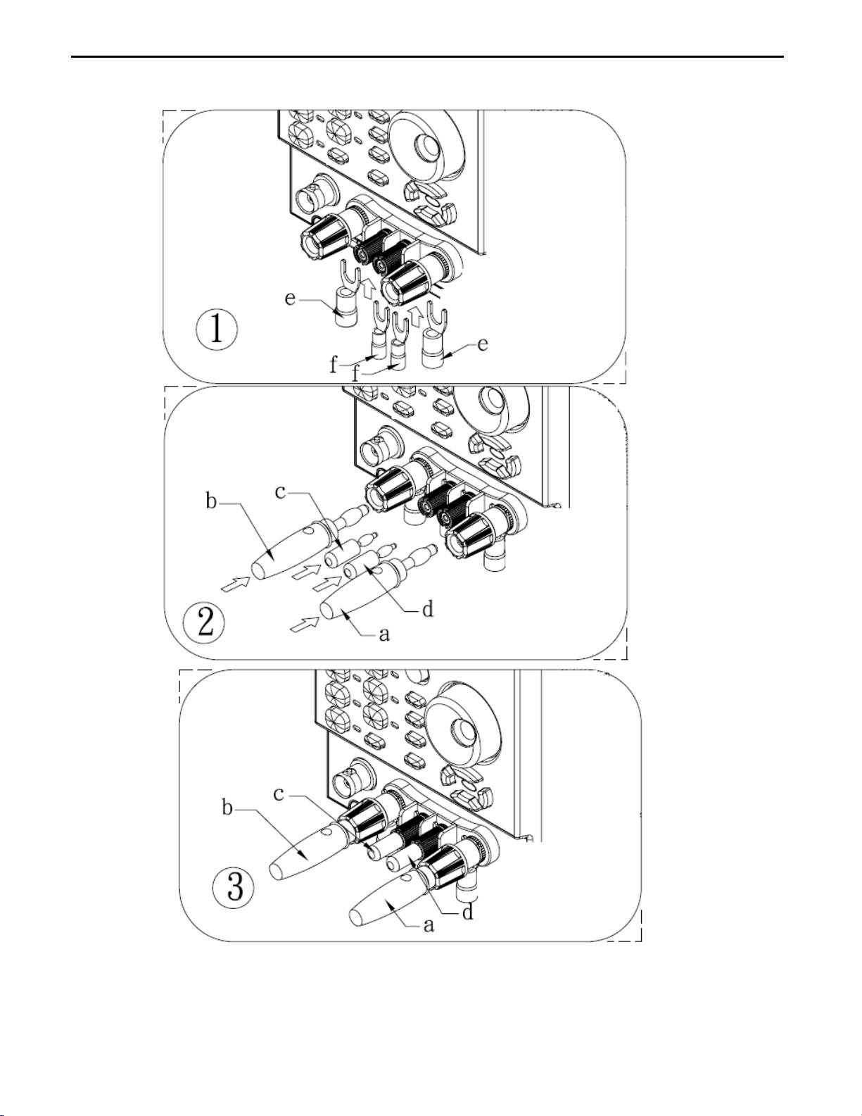
1.3.1 Accessories Installation Description
3110 Series Operation Manual 9
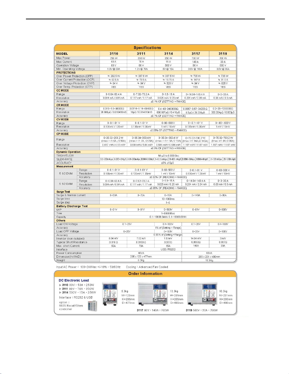
1-4 Specifications
Table 1-1 3110 Series Specification

10 PRODIGIT
Chapter 2 Installation
The 3110 Series was carefully inspected, tested and calibrated before shipment. If damage to
the instrument has occurred during transport, please inform Prodigit's sales and service office or
representative. Your 3110 series was shipped with a power cord for the type of outlet used at
your location. If the appropriated cord was not included, please contact your nearest sales office
to obtain the correct cord. Refer to "check line voltage" to check the line voltage selection and
fuse type.
2-1 Check line voltage
The 3110 Series can be operated from a 100/115 or 200/230Vac input as indicated on the
label on the rear panel. The input is switchable so please make sure that the switch is set
correctly for your nominal mains input before turning on the mains power. The procedure
below details how to change the switch position:
2.1.1 With the 3110 series power OFF, disconnect the power cord.
2.1.2 Refer the drawing on the rear panel in Fig 2-1, set the switches to the
Proper voltage as described in the following:
a. Set Switch to 100V/115V for 115Vac line voltage
b. Set Switch to 200V/230V for 230Vac
Note: 100Vac and 200Vac is used for Japan only (Option)
Fig 2-1 SET OF SWITCH

3110 Series Operation Manual 11
2-2 Input Fuse
This product is fitted with a mains input fuse. If it needs to be replaced please adhere to the
Following procedure.
2.2.1 Check the rating of the mains input fuse. Replace only with the correct
Type and rating.
For 100V/115Vac Input use T1A/250V (5*20mm),
For 200V/230Vac Input useT0.5A/250V (5*20mm)
2.2.2 The AC line fuse is located below the AC line socket (see Fig 2-2). Use
A small screwdriver to remove the fuse holder. Replace the failed fuse
With the appropriate type and rating according to your mains voltage.
(See Table 1-2)
2.2.3 Refit the fuse holder and connect the power cord.
Fig 2-2 FUSE RECEPTACLE
BEFORE replacing the fuse you must switch off the unit and mains power outlet and
disconnect the plug of the AC Power cable from the input socket of the 3110 series.
If prior to
exchanging the fuse, there is any abnormal noise or odour do not use the unit.
Please inform your local sales office to organise repair of the 3110 series.
To avoid the risk of fire or electronic shock the fuse must only be replaced with same type
and rating as the original. Any replacement fuse used should meet your national safety
standards. Any use of improper fuse or shorting the Fuse holder would be extremely
dangerous and would be strictly prohibited.
T1A/250V (5*20mm
)
T0.5A/250V (5*20mm)

12 PRODIGIT
2-3 Environmental requirements
•Indoor use.
•Measurement Category I.
•Pollution Degree 2.
•Relative Humidity 80% Max.
•Ambient Temperature 0 to +40°C
•Altitude up to 2000m.
•The equipment is not for measurements performed for CAT II, III and IV.
•Transient Overvoltage on the mains supply can be 2500V.
2-4 Observe the International Electrical Symbol listed below.
Warning!Risk of electric shock
Caution!Carefully read and understand the guidance in the operating manual
Before performing any action.
2-5 Cleaning
Use a soft or slightly damp cloth to clean this product.
BEFORE you clean the unit, switch the mains power off and disconnect the input lead.
・Please do NOT use any organic solvent capable of changing the nature of the plastic
such as benzene or acetone.
・Please ensure that no liquid is allowed to penetrate this product.
This manual suits for next models
5
Table of contents
Popular Laboratory Equipment manuals by other brands


COOK
COOK K-FTH-1012 Instructions for use

Zymo Research
Zymo Research ZymoPURE Plasmid Miniprep instruction manual

Agilent Technologies
Agilent Technologies Bravo Platform quick guide

Thermoline Scientific Equipment
Thermoline Scientific Equipment TO-152G operating instructions

Costway
Costway BB4878DE user manual

Halma
Halma Ocean Optics QE65000 Installation and operation manual