COOK K-FTH-1012 User manual

TEST TUBE HEATER
TEST TUBE HEATER
K-FTH-1012 Instructions for Use
K-FTH-1012
Instructions for Use
Manufacturer
WILLIAM A. COOK AUSTRALIA PTY. LTD.
95 Brandl Street, Brisbane Technology Park, Eight Mile Plains, Brisbane
QLD 4113, AUSTRALIA
EC Representative
COOK IRELAND LTD.
O’Halloran Road, National Technology Park, Limerick, IRELAND
© COOK 2019 IFU-KF TH-8

Language Index
Section
English ...............................................................................................................................................................
Kapitola
Česky ..................................................................................................................................................................
Afsnit
Dansk..................................................................................................................................................................
Abschnitt
Deutsch .............................................................................................................................................................
Apartado
Español..............................................................................................................................................................
Chapitre
Français .............................................................................................................................................................
Ενότητα
Ελληνικά............................................................................................................................................................
Sezione
Italiano...............................................................................................................................................................
Gedeelte
Nederlands ......................................................................................................................................................
Rozdział
Polski ..................................................................................................................................................................
Secção
Português.........................................................................................................................................................
Раздел
Русский.............................................................................................................................................................
Časť
Slovenčina........................................................................................................................................................
Luku
Suomi .................................................................................................................................................................
Avsnitt
Svenska .............................................................................................................................................................
Bölüm
Türkçe.................................................................................................................................................................
1
2
3
4
5
6
7
8
9
10
11
12
13
14
15
16
K-FTH-1012 Instructions for Use

K-FTH-1012 Instructions for Use English
1-1
General information
Copyright
This manual contains information that is subject to copyright. All rights reserved. This manual should
not be photocopied, duplicated on microlm or otherwise copied or distributed, completely or in part,
without the approval of William A. Cook Australia Pty. Ltd.
WARNING: Any adjustment, modication or repairs to the equipment should be carried out by persons
authorised to perform them.
WARNING: The equipment is to be used only with electrical systems complying with all IEC, CEC and NEC
requirements.
Some of the parts and equipment referred to in this manual bear registered trademarks but are not
identied as such. It should therefore not be assumed that the absence of the trademark indicates that
any given designation is not subject to trademark protection.
Users of William A. Cook Australia Pty. Ltd. products should not hesitate to contact us if there are any
unclear points or ambiguities in this manual.
Disposal of this product must be undertaken with regard to the WEEE directive (2002/96/EC).
This symbol indicates that this product may not be treated as municipal waste. Please ensure that this
product is properly disposed of as inappropriate waste handling of this product may cause potential
hazards to the environment and human health. For more detailed information about disposal of this
product, please contact your local city oce or Cook Medical Representative.
Cook fullls its legal obligations with regards to WEEE and Waste Packaging compliance through our
own takeback initiatives and through national takeback schemes.
Please see https://www.cookmedical.com/about/sustainability-environmental-practices/waste-
electrical-electronic-equipment-directive/ for details on how to properly recycle WEEE or waste
packaging in your country.
© Cook 2019
Document No: IFU-KFTH-8
Service Address:
Please refer to your local Cook Medical distributor for details of your nearest authorised service agent.
1

K-FTH-1012 Instructions for Use English
1-2
Table of contents
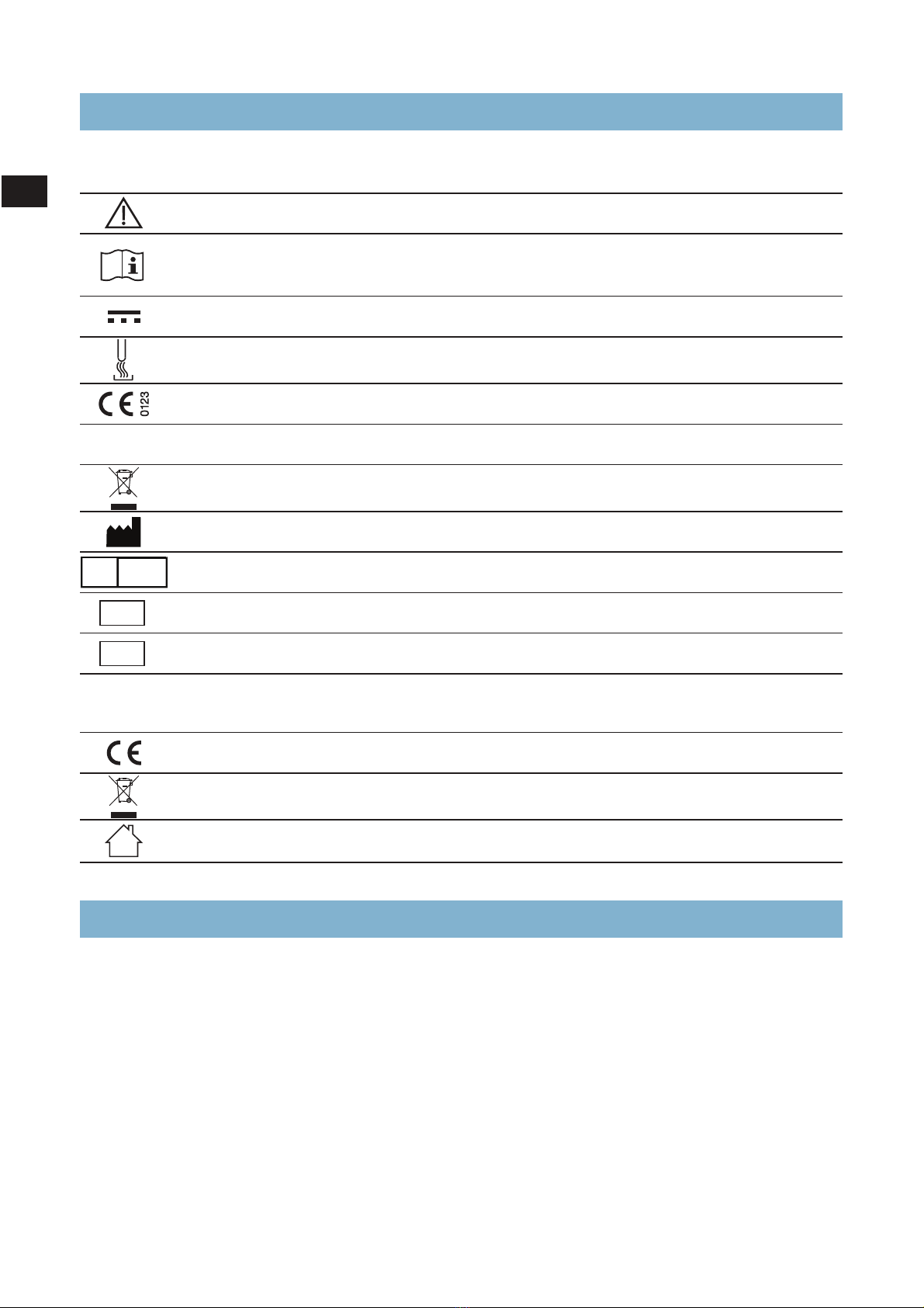
EXPLANATION OF PICTOGRAMS ..................................................................13
HOW TO USE THIS MANUAL .......................................................................13
1. SAFETY INSTRUCTIONS .........................................................................14
1.1 Warnings . . . . . . . . . . . . . . . . . . . . . . . . . . . . . . . . . . . . . . . . . . . . . . . . . . . . . . . . . . . . . . . . . . . . . . . . . . . . . . . . . . . . . . . . . 1-5
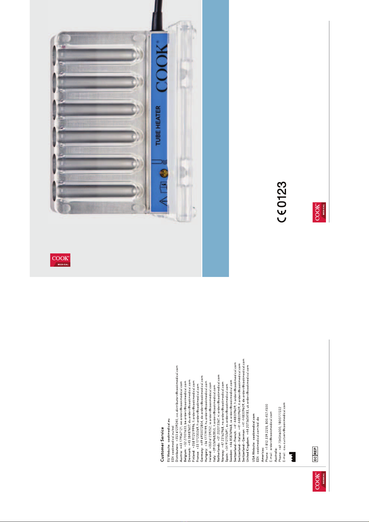
2. ABOUT THE KFTH1012 TEST TUBE HEATER . . . . . . . . . . . . . . . . . . . . . . . . . . . . . . . . . . . . . . . . . . . . . . . . . . 16
2.1 Intended use . . . . . . . . . . . . . . . . . . . . . . . . . . . . . . . . . . . . . . . . . . . . . . . . . . . . . . . . . . . . . . . . . . . . . . . . . . . . . . . . . . . . . 1-6
2.1.1 Intended users and use environment. . . . . . . . . . . . . . . . . . . . . . . . . . . . . . . . . . . . . . . . . . . . . . . . . . . . . . . . 1-6
2.2 Contraindications . . . . . . . . . . . . . . . . . . . . . . . . . . . . . . . . . . . . . . . . . . . . . . . . . . . . . . . . . . . . . . . . . . . . . . . . . . . . . . . . 1-6
2.3 Device description. . . . . . . . . . . . . . . . . . . . . . . . . . . . . . . . . . . . . . . . . . . . . . . . . . . . . . . . . . . . . . . . . . . . . . . . . . . . . . . . 1-6
2.4 Precautions for device use . . . . . . . . . . . . . . . . . . . . . . . . . . . . . . . . . . . . . . . . . . . . . . . . . . . . . . . . . . . . . . . . . . . . . . . . 1-6
3. INSTALLATION AND SETUP.................................................................... 16
3.1 Unpacking. . . . . . . . . . . . . . . . . . . . . . . . . . . . . . . . . . . . . . . . . . . . . . . . . . . . . . . . . . . . . . . . . . . . . . . . . . . . . . . . . . . . . . . . 1-6
3.2 Device placement . . . . . . . . . . . . . . . . . . . . . . . . . . . . . . . . . . . . . . . . . . . . . . . . . . . . . . . . . . . . . . . . . . . . . . . . . . . . . . . . 1-6
3.3 Supply voltage selection . . . . . . . . . . . . . . . . . . . . . . . . . . . . . . . . . . . . . . . . . . . . . . . . . . . . . . . . . . . . . . . . . . . . . . . . . 1-7
3.4 Electromagnetic compatibility . . . . . . . . . . . . . . . . . . . . . . . . . . . . . . . . . . . . . . . . . . . . . . . . . . . . . . . . . . . . . . . . . . . 1-7
4. OPERATION OF THE DEVICE. . . . . . . . . . . . . . . . . . . . . . . . . . . . . . . . . . . . . . . . . . . . . . . . . . . . . . . . . . . . . . . . . . . . . 18
4.1 Front of the device. . . . . . . . . . . . . . . . . . . . . . . . . . . . . . . . . . . . . . . . . . . . . . . . . . . . . . . . . . . . . . . . . . . . . . . . . . . . . . . . 1-8
4.2 Rear of the device . . . . . . . . . . . . . . . . . . . . . . . . . . . . . . . . . . . . . . . . . . . . . . . . . . . . . . . . . . . . . . . . . . . . . . . . . . . . . . . . 1-8
4.3 Turning the unit on . . . . . . . . . . . . . . . . . . . . . . . . . . . . . . . . . . . . . . . . . . . . . . . . . . . . . . . . . . . . . . . . . . . . . . . . . . . . . . . 1-9
4.4 Initial heating of the unit . . . . . . . . . . . . . . . . . . . . . . . . . . . . . . . . . . . . . . . . . . . . . . . . . . . . . . . . . . . . . . . . . . . . . . . . . 1-9
4.5 Placement of test tubes. . . . . . . . . . . . . . . . . . . . . . . . . . . . . . . . . . . . . . . . . . . . . . . . . . . . . . . . . . . . . . . . . . . . . . . . . . . 1-9
4.6 Turning the unit o . . . . . . . . . . . . . . . . . . . . . . . . . . . . . . . . . . . . . . . . . . . . . . . . . . . . . . . . . . . . . . . . . . . . . . . . . . . . . . . 1-9
5. ALARM CONDITIONS ........................................................................... 19
5.1 Unit insuciently heated . . . . . . . . . . . . . . . . . . . . . . . . . . . . . . . . . . . . . . . . . . . . . . . . . . . . . . . . . . . . . . . . . . . . . . . . . 1-9
5.2 Unit at operating temperature. . . . . . . . . . . . . . . . . . . . . . . . . . . . . . . . . . . . . . . . . . . . . . . . . . . . . . . . . . . . . . . . . . . . 1-9
5.3 Overheating Alarm . . . . . . . . . . . . . . . . . . . . . . . . . . . . . . . . . . . . . . . . . . . . . . . . . . . . . . . . . . . . . . . . . . . . . . . . . . . . . . . 1-9
5.4 Disconnection Alarm . . . . . . . . . . . . . . . . . . . . . . . . . . . . . . . . . . . . . . . . . . . . . . . . . . . . . . . . . . . . . . . . . . . . . . . . . . . . 1-10
5.5 Insucient Power Alarm. . . . . . . . . . . . . . . . . . . . . . . . . . . . . . . . . . . . . . . . . . . . . . . . . . . . . . . . . . . . . . . . . . . . . . . . . 1-10
6. SERVICE AND MAINTENANCE. . . . . . . . . . . . . . . . . . . . . . . . . . . . . . . . . . . . . . . . . . . . . . . . . . . . . . . . . . . . . . . . . 110
6.1 Cleaning the device. . . . . . . . . . . . . . . . . . . . . . . . . . . . . . . . . . . . . . . . . . . . . . . . . . . . . . . . . . . . . . . . . . . . . . . . . . . . . . 1-10
6.2 Periodic inspection . . . . . . . . . . . . . . . . . . . . . . . . . . . . . . . . . . . . . . . . . . . . . . . . . . . . . . . . . . . . . . . . . . . . . . . . . . . . . . 1-10
6.3 Inspection by an authorised service agent. . . . . . . . . . . . . . . . . . . . . . . . . . . . . . . . . . . . . . . . . . . . . . . . . . . . . . . 1-11
6.4 Returning the device . . . . . . . . . . . . . . . . . . . . . . . . . . . . . . . . . . . . . . . . . . . . . . . . . . . . . . . . . . . . . . . . . . . . . . . . . . . . 1-11
7. TECHNICAL DATA .............................................................................. 112
8. TROUBLESHOOTING. . . . . . . . . . . . . . . . . . . . . . . . . . . . . . . . . . . . . . . . . . . . . . . . . . . . . . . . . . . . . . . . . . . . . . . . . . . 117
9. LIMITED WARRANTY . . . . . . . . . . . . . . . . . . . . . . . . . . . . . . . . . . . . . . . . . . . . . . . . . . . . . . . . . . . . . . . . . . . . . . . . . . 117
9.1 Liability . . . . . . . . . . . . . . . . . . . . . . . . . . . . . . . . . . . . . . . . . . . . . . . . . . . . . . . . . . . . . . . . . . . . . . . . . . . . . . . . . . . . . . . . . . 1-18
9.2 Life of Product . . . . . . . . . . . . . . . . . . . . . . . . . . . . . . . . . . . . . . . . . . . . . . . . . . . . . . . . . . . . . . . . . . . . . . . . . . . . . . . . . . . 1-18
1

K-FTH-1012 Instructions for Use English
1-3
The following pictograms appear on the K-FTH-1012 Test Tube Heater
Before connection, read the manual
Consult the operating instructions for information needed for the proper use
of the device
Direct current
Test Tube Heater
CE Mark Approval
Degree of enclosure protection from dust and water sprayed from all directions
Dispose of in accordance with WEEE directive (2012/19/EU)
Manufacturer
EC Representative
Catalogue Code
Serial Number
The following pictograms appear on the K-APS-300 Power Supply
CE Mark Approval
Dispose of in accordance with WEEE directive (2012/19/EU)
For indoor use only
IP64
EC
REP
REF
SN
Explanation of pictograms
Please read this manual completely and follow its instructions carefully. The words WARNING, CAUTION
and NOTE carry special meanings and they should be read carefully.
WARNING:
The personal safety of the patient may be involved. Disregarding this information could result in injury
to the patient or operator, or damage to the device or contents.
CAUTION:
These instructions point out special service procedures or pre-cautions that you must follow to avoid
damaging the device.
NOTE:
This provides special information that facilitates maintenance or claries important instructions.
Please pay particular attention to the Safety Instructions.
How to use this manual
1

K-FTH-1012 Instructions for Use English
1-4
1
Read this manual
Please familiarise yourself with the contents of the manual before using the device. Failure to follow
these instructions may result in injuries to both the patient and the user. Medical accessories and
devices may be used only by physicians or medical assistants under the direction of a physician with
the appropriate technical qualication.
Who should use this manual?
The manual is addressed to physicians or medical assistants with an appropriate qualication. These
persons are authorised to operate this device.
Federal law
Federal Law (U.S.A.) restricts this device to use by or on the order of a physician.
Care and maintenance
To guarantee safe operation, it is absolutely necessary to carry out proper care and maintenance of the
device and accessories. For the protection of the patient and the operating team, check that the device
is complete and functional before each use.
Brand new products as well as repaired products must be prepared and tested according to the
manual instructions before you use them for the rst time.
Service agent
The manufacturer has the exclusive right to train and certify authorised service agents.
Biohazard
All devices or accessory parts that are sent in to be repaired must be prepared for transportation as
described in the manual, for the protection of the service personnel and for safety during transportation.
If this is not possible, the contaminated product must be clearly marked with a contamination warning
and should be doubly sealed in safety foil.
1. Safety instructions

K-FTH-1012 Instructions for Use English
1-5
1.1 Warnings
Reading the manual
This manual describes the operation and the intended use of the device and the accessories.
It is essential to use this manual to familiarise yourself with the functions and the operation of the
device before using it in the operating room.
Not following the manual instructions can result in serious injury to the patient or the operating team
and can lead to damage or breakdown of the device and accessories.
Professional qualication
This manual does not provide a detailed description of operation technologies, nor is it suitable for
introducing a beginner to this operating technique. Medical accessories and devices may be used only
by physicians and medical assistants under the direction of a physician with the appropriate technical
qualication.
Replacement device and accessories
In case the device fails during an operation, a replacement device and replacement accessories should
be kept within reach so that the operation may be completed.
Available voltage
Determine if the available voltage corresponds to your device. Working with the wrong voltage will
cause malfunction or destruction of the device.
Not explosion proof
Electrical components are not explosion proof. Do not use in an area where ammable gases are
present.
Risk of electrical shock
To reduce the risk of electrical shock, do not remove cover (or back). Refer servicing to qualied service
personnel.
No user serviceable parts inside.
Internal temperature setting
The set temperature of the device is factory pre-set to 36.9°C prior to delivery. The set temperature
may not be that required by a doctor during an operation, for which the doctor is responsible.
Cleaning the device
Do not sterilise the device. Do not immerse the device.
Power supply
Electrical shock hazard present. Do not use in the presence of ammable anaesthetics. No attempt
should be made to open the unit casing. Should any electrical or mechanical fault occur while using
the K-FTH-1012, please contact your nearest authorised service agent or Cook Distributor.
1

K-FTH-1012 Instructions for Use English
1-6
1
2.1 Intended use
The K-FTH-1012 Test Tube Heater is intended to hold test tubes containing aspirated follicular uid at a
specied temperature.
2.1.1 Intended users and use environment
The Test Tube Heater is intended to be used by obstetrician-gynaecologists and nursing sta who have
received specialised training in the eld of obstetrics and gynaecology.
The Test Tube Heater is intended to be used in a sterile environment, such as an operation theatre, day
surgery theatre or fertility clinic.
2.2 Contraindications
There are no known contraindications for these devices.
2.3 Device description
The Test Tube Heater is an electronically controlled heating unit powered by a 12 V DC power supply
and is designed to accept up to six 14 mL test tubes.
2.4 Precautions for device use
In the event of any electrical or mechanical fault during use, cease use of the device until it has been
checked by an authorised service agent. Use only with the provided Cook K-APS-300 Power Supply.
3. Installation and set-up
3.1 Unpacking
Check the device and all accessories immediately upon receipt to make sure the contents are complete
and that nothing is damaged. The manufacturer will only honour claims for compensation which are
forwarded immediately to the sales representative or the authorised service company.
3.2 Device placement
Do not allow the Power Supply to come into contact with liquids. Place the Test Tube Heater on a level
surface away from strong draughts.
The device is factory calibrated to maintain the contents of test tubes at 36.9°C when operated in an
ambient temperature of 23°C ± 2°C.
If a dierent set temperature is desired or the device is to be used in ambient temperature conditions
which are dierent to the conditions used during factory calibration, the device shall require
re-calibration by an authorised service agent.
Position the device such that quick and easy disconnection of the power supply plug is not impeded.
WARNING: The Test Tube Heater should not be used adjacent to or stacked with other equipment. If adjacent
or stacked use is necessary, the device should be monitored to verify normal operation in the conguration in
which it will be used.
2. About the K-FTH-1012 Test Tube Heater

K-FTH-1012 Instructions for Use English
1-7
1
IMPORTANT NOTE: Use of cables other than those specied or provided by the manufacturer of this
equipment could result in increased electromagnetic emissions or decreased electromagnetic immunity of
this equipment and result in improper operation.
3.3 Supply voltage selection
The Test Tube Heater can operate from supply voltages ranging from 100 to 240 VAC, 50 to 60 Hz. No
fuse selection is required. To avoid the risk of electric shock, equipment must only be connected to a
supply mains with protective earth.
WARNING: EXPLOSION HAZARD: Do not use the Test Tube Heater in the presence of ammable gases!
CAUTION: Determine if the available voltage corresponds to your device. Working with the wrong voltage
will cause the device to malfunction or may permanently damage the device.
The electrical components are not explosion proof. Do not use in an area where ammable gases are present.
3.4 Electromagnetic compatibility
The Test Tube Heater is designed to maintain the temperature of aspirated follicular uid within a test
tube at a specied temperature with infrequent failures. It has been tested and found to comply with
the electromagnetic compatibility (EMC) limits for medical devices as specied by IEC 60601-1-2:2014.
These limits are designed to provide reasonable protection against harmful interference in a typical
medical installation.
Medical electrical equipment requires special precautions regarding EMC and must be installed and
operated according to these instructions. It is possible that high levels of radiated or conducted radio-
frequency electromagnetic interference (EMI) from portable and mobile RF communications equipment
or other strong or nearby radio-frequency sources could result in performance disruption of the Test
Tube Heater. Evidence of disruption may include erratic ashing of the indicator light, equipment
ceasing to operate, or other incorrect functioning. If this occurs cease using the Test Tube Heater and
contact your Cook authorised service agent.
Refer to the tables in §7 of this manual for guidance on electromagnetic emissions,
electromagnetic immunity, and recommended separation distance between portable and mobile RF
communications equipment and the Test Tube Heater.

K-FTH-1012 Instructions for Use English
1-8
1
4.1 Front of the device
Representative view only.
1. Removable acrylic cover (re-order code K-FTH-1012-CP)
2. Test Tube heating compartments
3. Heater On indicator light
4. Removable acrylic K-FTH-1012 stand
5. Power cable entry
4.2 Rear of the device
Representative view only.
1
2
3
4
5
4. Operation of the device

K-FTH-1012 Instructions for Use English
1-9
4.3 Turning the unit on
Connect the power cable of the Test Tube Heater to the K-APS-300 power supply.
The amber indicator light (3) will glow and a short single tone will sound when the power supply is
turned on.
4.4 Initial heating of the unit
1. When the power supply has been turned on, the amber indicator light (3) will glow continuously, if
the unit is not already heated to the operating temperature.
NOTE: If beginning at ambient room temperature the unit takes approximately ve minutes to heat up to
the optimal operating temperature. During this time the amber indicator light (3) will glow continuously.
2. When the unit has reached the set operating temperature the amber indicator light (3) will begin to
ash slowly. The unit is now ready to be used.
3. Throughout the use of the unit the operating temperature will be thermostatically maintained.
4. If the output voltage of the power supply is inadequate, an audible tone will sound indicating that
the device may not be able to maintain the set temperature.
4.5 Placement of test tubes
5. The Test Tube Heater has been designed to accept Falcon® 2001 Series test tubes. Any number, up to
six, can be used at the same time.
6. All test tubes should be placed in the test tube heating compartments (2) through the openings in
the top of the unit. The test tube should t snug in the appropriate test tube heating compartment
(2) without using excessive force.
7. No lubricant should be used on the outside of the test tube or in the heating compartment (2).
4.6 Turning the unit o
8. When the power supply to the Test Tube Heater is disconnected, the amber indicator light (3) will
turn o. A single audible tone will also sound to alert the user to power disconnection.
5. Alarm conditions
The Test Tube Heater uses both audible and visual indicators for a variety of conditions.
5.1 Unit insuciently heated
When the unit is “ON” but not at the operating temperature the amber indicator light (3) will glow
continuously. The unit should not be used when in this condition.
5.2 Unit at operating temperature
When the unit has reached its operating temperature (within approx. 1°C) the amber indicator light (3)
will begin to ash slowly. The unit should only be used when in this condition.
5.3 Overheating Alarm
If the temperature of the unit exceeds the preset temperature a secondary safety circuit will be activated
preventing overheating of the test tube contents. In this alarm condition:
• The amber indicator light will turn o and no further heating of the unit will occur.
• A continuous audible tone will sound until the temperature drops to preset temperature.
Note: If the ambient temperature of the environment is high, the overheating alarm may activate.
The unit will not commence heating until the ambient temperature falls below the preset temperature.
The overheating alarm will activate again when the temperature of the unit exceeds the preset
temperature. This cycle will be repeated as long as the ambient temperature remains high.
1

K-FTH-1012 Instructions for Use English
1-10
1
5.4 Disconnection Alarm
Each time the power supply to the unit is disconnected or turned o a single audible tone will sound to
alert the user.
5.5 Insucient Power Alarm
If the output voltage of the power supply is inadequate, an audible tone will sound.
6. Service and maintenance
To preserve the device and ensure its proper functioning, proper service, maintenance and storage
must be provided for. To protect the patient from infections, all accessory items that come into contact
with human tissue (example test tubes and tubing) must be sterile. Accessory items must be discarded
after each patient use.
6.1 Cleaning the device
WARNING: Electric shock hazard.
CAUTION: Do not sterilise the Test Tube Heater or Power Supply. Do not immerse the Test Tube Heater or
Power Supply. Do not clean the Power Supply with uids. After each use of the Test Tube Heater, disconnect
the device from the Power Supply.
Use a hydrous disinfecting solution or a 70% isopropyl alcohol solution to clean the exterior of the Test
Tube Heater. Follow instructions provided by the disinfectant manufacturer to determine the correct
uid concentration. Moisten a cloth with the disinfectant solution and wipe the surface of the device.
The front acrylic panel may be removed in order to facilitate cleaning. Do not submerge the unit in the
disinfectant solution.
The Power Supply may be cleaned with a dry cloth only. It is not suitable for any other methods of
cleaning. Never clean the Power Supply with uids.
6.2 Periodic inspection
To maintain the device integrity and functionality, it is recommended that the device be inspected
regularly by the device owner or user for any sign of wear or deterioration, e.g. if the cable sheath is
cracked or broken, or damage to the enclosure which may allow liquids to enter the device.
Regular inspections will assist in early detection of possible malfunctions. This helps preserve the
device and maintains its safety.
It is recommended that the temperature set point is tested on a biannual basis using the following
method:
Turn the unit on as described in §4.3.
To measure the temperature:-
1. Insert a capped test tube into each of the wells except the second left.
2. Insert a modied test tube in the second left well.
3. Pour 6.5 mL of water into the modied test tube and insert the thermometer through the hole in the
cap.
4. Ensure that the water level now covers the entire bulb and that the bulb is centred in the test tube,
ie not touching tube wall.
5. Ensure the device is tested where it is intended to be used
6. Allow enough time for the thermometer to thermally equilibrate.

K-FTH-1012 Instructions for Use English
1-11
11. Thermometer
2. Modied Test Tube Cap to allow a thermometer to be inserted
3. 6.5 mL of water
1
2
3
The temperatures measured should be the set temperature ± 1.0°C. (Standard factory set point is 36.9°C)
6.3 Inspection by an authorised service agent
Inspections at least once a year
For ongoing operational safety of the device, the device must be maintained at regular intervals by an
authorised service agent as per SMM30004. The service agent will verify the performance of the device.
Depending on the duration and frequency of use, the device should be maintained at least once a year.
Failure to adhere to this maintenance schedule will result in the manufacturer refusing liability for the
operational safety of the device.
Authorised service agents
All services such as alterations, repairs, calibrations etc., may only be performed by the manufacturer or
by service agents who are authorised by the manufacturer as per SMM30004.
Liability
The manufacturer is free from all liability for the operational safety of the device if the device has been
wilfully opened and unauthorised persons have performed repairs or alterations on it.
Certication
The device owner should receive a certicate from the service technician for all inspections or repairs.
This certicate states the type and scope of the services rendered, the service date and the name of the
service company. The certicate should be signed.
Technical documentation
If the manufacturer provides you with technical documentation, this does not authorise the user to
perform repairs, adjustments or alterations to the device or accessories.
6.4 Returning the device
If it becomes necessary to return the device, use of the original packaging is required. The
manufacturer does not take responsibility for damage that has occurred during transportation if the
damage was caused by inadequate transport packaging. Please enclose the following information with
the device:
• owner’s name
• owner’s address
• model type
• Unique Device Identier of the equipment (printed under barcode on the rear of the device)
• description of the damage or fault
The manufacturer has the right to refuse to carry out repairs if the products it receives are contaminated.

K-FTH-1012 Instructions for Use English
1-12
1
7. Technical data
Classication according to IEC 60601-1
Type of protection against electric shock: Class I equipment
Degree of protection against electric shock: Type B
Degree of protection against harmful
ingress of solids and water:
Test Tube Heater: IP64
Power Supply: IP20
General specications
Power supply (voltage): 100 - 240 VAC
Frequency: 50 - 60 Hz
Maximum current: 1.1 A
Environmental Operating Conditions: +15 to +30°C
10 to 90% RH
700 hPa to 1060 hPa
Storage and transport directions: -10 to +50°C
5 to 90% RH
Manufactured and tested to the following
standards:
IEC 60601-1: 1988+A1:1991+A2:1995
IEC 60601-1: 2005 + A1: 2012(E)
IEC 60601-1-2: 2014
Set temperature accuracy: ± 1 °C
Dimensions:
Test Tube Heater:
150 x 100 x 28 mm (excluding base/cable)
Power Supply:
121 x 50 x 31 mm (excluding cables)
Weight: Test Tube Heater: 0.7 kg
Power Supply: 0.3 kg
Guidance and manufacturer’s declaration – electromagnetic emissions
The Test Tube Heater is intended for use in the electromagnetic environment specied below. The
customer or the end user of the Test Tube Heater should assure that it is used in such an environment.
Emissions Test Compliance Electromagnetic Environment Guidance
RF emissions
CISPR 11 Group 1
The Test Tube Heater uses RF energy only for its
internal function. Therefore, its RF emissions are very
low and are not likely to cause any interference in
nearby electronic equipment.
RF emissions
CISPR 11 Class B The Test Tube Heater is suitable for use in all
establishments, including domestic establishments and
those directly connected to the public low voltage
power supply network that supplies buildings used for
domestic purposes.
Harmonic emissions
IEC 61000-3-2 Class A
Voltage uctuations/
icker emissions
IEC 61000-3-3
Complies

K-FTH-1012 Instructions for Use English
1-13
1
Guidance and manufacturer’s declaration – electromagnetic immunity
The Test Tube Heater is intended for use in the electromagnetic environment specied below. The
customer or the end user of the Test Tube Heater should assure that it is used in such an environment.
Immunity Test IEC 60601 Test Level Compliance Level Electromagnetic Environment
Guidance
Electrostatic
discharge (ESD)
IEC 61000-4-2
± 8 kV contact
± 15 kV air
± 8 kV contact
± 15 kV air
Floors should be wood,
concrete or ceramic tile. If oors
are covered with synthetic
material, the relative humidity
should be at least 30%.
Electrical fast
transient
(EFT)
IEC 61000-4-4
± 2 kV for power
supply lines
± 1 kV for
input/output lines
± 2 kV for power
supply lines
Not applicable for
input/output lines
Mains power quality should be
that of a typical commercial or
hospital environment.
Surge
IEC 61000-4-5
± 1 kV line-to-line
± 2 kV line-to-ground
± 1 kV line-to-line
± 2 kV line-to-ground
Mains power quality should be
that of a typical commercial or
hospital environment.
Voltage dips, short
interruptions and
voltage variations
on power supply
input lines
IEC 61000-4-11
0% UT for 0.5 cycle at
0°, 45°, 90°, 135°, 180°,
225°, 270° and 315°
0% UT for 1 cycle
and
70% for 0.5 seconds
0% UT for 5 seconds
0% UT for 0.5 cycle at
0°, 45°, 90°, 135°, 180°,
225°, 270° and 315°
0% UT for 1 cycle
and
70% for 0.5 seconds
0% UT for 5 seconds
Mains power quality should be
that of a typical commercial or
hospital environment. If the
user of the Test Tube Heater
requires continued operation
during power mains
interruptions, it is
recommended that the Test
Tube Heater be powered from
an uninterruptible power
supply or a battery.
Power frequency
(50/60Hz) magnetic
eld IEC 61000-4-8
30 A/m 30 A/m Power frequency magnetic
elds should be at levels
characteristic of a typical
location in a typical commercial
or hospital environment.

K-FTH-1012 Instructions for Use English
1-14
1
Guidance and manufacturer’s declaration – electromagnetic immunity (continued)
Conducted RF
IEC 61000-4-6
3Vrms
0.15 to 80MHz
6Vrms in ISM bands
Between 0.15MHz
and 80MHzc
80% AM at 1kHz
3Vrms
0.15 to 80MHz
6Vrms in ISM bands
Between 0.15MHz
and 80MHzc
80% AM at 1kHz
Portable and mobile RF communications
equipment should be used no closer to
any part of the Test Tube Heater,
including cables, than the recommended
separation distance calculated from the
equation applicable to the frequency of
the transmitter.
Recommend separation distance
d = 0.6 √P
Recommend separation distance
d = 1.2 √P 80 MHz to 800 MHz
d = 2.3 √P 800 MHz to 2.5 GHz
where P is the maximum output power
rating of the transmitter in watts (W)
according to the transmitter
manufacturer and d is the
recommended separation distance in
metres (m).
Field strengths from xed RF
transmitters, as determined by an
electromagnetic site surveyashould be
less than the compliance level in each
frequency rangeb. Interference may
occur in the vicinity of equipment
marked with the following symbol:
Radiated RF
IEC 61000-4-3
3V/m
80MHz to 2.5GHz
80% AM at 1kHz
3V/m
80MHz to 2.5GHz
80% AM at 1kHz
Proximity elds from RF wireless communications equipment IEC 61000-4-3.
Note 1: At 80 MHz and 800 MHz, the higher frequency range applies.
Note 2: These guidelines may not apply in all situations. Electromagnetic propagation is aected by
absorption and reection from structures, objects and people.
aField strengths from xed transmitters, such as base stations for radio (cellular/cordless) telephones
and land mobile radios, amateur radio, AM and FM radio broadcast and TV broadcast cannot be
predicted theoretically with accuracy. To assess the electromagnetic environment due to xed RF
transmitters, an electromagnetic site survey should be considered. If the measured eld strength in
the location in which the Test Tube Heater is used exceeds the applicable RF compliance level above,
the Test Tube Heater should be observed to verify normal operation. If abnormal performance is
observed, additional measures may be necessary, such as reorienting or relocating the Test Tube
Heater.
bOver the frequency range 150 kHz to 80MHz, eld strengths should be less than 3 V/m.
cThe ISM (industrial. scientic and medical) bands between 0.15MHz and 80MHz are 6.765MHz to
6.795MHz; 13.553MHz to 13.567MHz; 26.957MHz to 27.283MHz; and 40.66MHz to 40.70MHz. The
amateur radio bands between 0.15MHz and 80MHz are 1.8MHz to 2.0MHz; 3.5MHz to 4.0MHz; 5.3MHz
to 5.4MHz; 7.0MHz to 7.3MHz; 10.1MHz to 10.15MHz; 14MHz to 14.2MHz, 18.07MHz to 18.17MHz;
21.0MHz to 21.4MHz; 24.89MHz to 24.99MHz; 28.0MHz to 29.7MHz; and 50.0 MHz to 54.0MHz.

K-FTH-1012 Instructions for Use English
1-15
1
Recommended separation distance between portable and mobile RF communications
equipment and the Test Tube Heater
The Test Tube Heater is intended for use in an electromagnetic environment in which radiated RF
disturbances are controlled. The customer or the user of the Test Tube Heater can help prevent
electromagnetic interference by maintaining a minimum distance between portable and mobile RF
communications equipment (transmitters) and the Test Tube Heater as recommended below,
according to the maximum output power of the communications equipment.
Rated maximum
output power
of transmitter
W
Separation distance according to frequency of transmitter
m
150 kHz to 80 MHz
d = 1.2 √P
80 MHz to 800 MHz
d = 1.2 √P
800 MHz to 2.5 GHz
d = 2.3 √P
0.01 0.12 0.12 0.23
0.1 0.38 0.38 0.73
1 1.2 1.2 2.3
10 3.8 3.8 7.3
100 12 12 23
For transmitters rated at a maximum output power not listed above, the recommended separation
distance d in metres (m) can be estimated using the equation applicable to the frequency of the
transmitter, where P is the maximum output power rating of the transmitter in watts (W) according to
the transmitter manufacturer.
Note 1: At 80 MHz and 800 MHz, the separation distance for the higher frequency range applies.
Note 2: These guidelines may not apply in all situations. Electromagnetic propagation is aected by
absorption and reection from structures, objects, and people

K-FTH-1012 Instructions for Use English
1-16
1
Proximity elds from RF wireless communication equipment
Test
frequency
(MHz)
Banda
(MHz)
ServiceaModulationb
Maximum
power
(W)
Distance
(m)
Immunity
test level
(V/m)
Minimum
separation
distance
(m)
385 360-390 TETRA 400
Pulse
modulationb
18 Hz
1.8 0.3 27 0.3
450 430-470 GMRS 460
FRS 460
FMC
±5 kHz deviation
1 kHz sine
2 0.3 28 0.3
710
704-787 LTE Band 13,17
Pulse
modulationb
217 Hz
0.2 0.3 9 0.3745
780
810
800-960
GSM 800/900
TETRA 800
iDEN 820
CDMA 850
LTE Band 5
Pulse
modulationb
217 Hz
2 0.3 28 0.3
870
930
1720
1700-1990
GSM 1800
CDMA 1900
DECT
LTE Band 1, 3,
4, 25; UMTS
Pulse
modulationb
217 Hz
2 0.3 28 0.3
1845
1970
2450 2400-2570
Bluetooth
WLAN
802.11 b/g/n
RFID 2450
LTE Band 7
Pulse
modulationb
217 Hz
2 0.3 28 0.3
5240
5100-5800 WLAN 802.11
a/n
Pulse
modulationb
217 Hz
0.2 0.3 9 0.35500
5785
Note: if necessary to achieve the IMMUNITY test level, the distance between the transiting antenna
and the ME equipment or ME system may be reduced to 1m. The 1m test distance is permitted
by IEC 61000-4-3.
aFor some services, only the uplink frequencies are included.
bThe carrier shall be modulated using a 50% duty cycle square wave signal.
cAs an alternative to FM modulation, 50% pulse modulation at 18Hz may be used because while it does
not represent actual modulation, it would be worst case.

K-FTH-1012 Instructions for Use English
1-17
1
8. Troubleshooting
Error and alarm indicator Source of error Elimination of error
Indicator light does not
illuminate.
Power supply is not connected. Check the power supply
connection.
Incorrect voltage. Contact your nearest service
agent.
Indicator light does not
illuminate and a single
continuous tone sounds.
Factors in the environment
may have warmed the unit
above the set temperature.
Check the ambient temperature
and remove the unit to cooler
environment. Allow the unit to
cool for 10 minutes and then turn
on. If the unit heats up but then
sounds the overheating alarm
again, contact your nearest
service agent.
A continuous audible tone
sounds.
Power supply inadequate. Check that the power supply lead
of the Test Tube Heater is rmly
connected to the K-APS-300
Power Supply.
William A. Cook Australia Pty. Ltd. warrants to the purchasers of this device that at time of manufacture,
the product was prepared and tested in accordance with good manufacturing practices and guidelines
specied by the relevant competent authority.
In the event of product failure under normal use, due to defects in material or workmanship, within a
period of one (1) year from the date of purchase, the product will be repaired, or at Cook’s option,
replaced, at no charge. This limited warranty does not apply to products subjected to abnormal use,
conditions, improper storage or damaged by accident, misuse, improper line voltage or to products
altered or serviced by anyone other than William A. Cook Australia Pty. Ltd. or its authorised agent.
The foregoing limited warranty is exclusive and in lieu of all other warranties whether written, oral,
expressed or implied. In particular, William A. Cook Australia Pty. Ltd. does not warrant that the
product is suitable for the needs of the purchaser and there are no warranties given as to merchant-
ability or tness for a particular purpose. William A. Cook Australia Pty. Ltd. representations concerning
tness for purpose or suitability for use by any purchaser does not extend beyond those representations
set out in the William A. Cook Australia Pty. Ltd. literature that accompanies the product. William A.
Cook Australia Pty. Ltd. assumes that the purchaser is experienced in the use of this device and is able
to judge from his/her own expertise the suitability or otherwise of the product for the intended use.
William A. Cook Australia Pty. Ltd. conducts a technical advisory service which can be consulted by a
purchaser or intended purchaser on an advisory basis.
After one (1) year from the date of purchase, this device will be repaired for a repair charge equal to the
cost of parts, labour and transport.
Before returning a product for any reason, please contact your nearest Cook distributor for assistance
and instructions.
William A. Cook Australia Pty. Ltd. reserves the right to change or discontinue this product without
notice.
9. Limited warranty

K-FTH-1012 Instructions for Use English
1-18
1
9.1 Liability
Because William A. Cook Australia Pty. Ltd. has no control or inuence over the conditions under which
this device is used, over its method of use or administration, or on handling of the product after it
leaves its possession, William A. Cook Australia Pty. Ltd. takes no responsibility for the results, use and/
or performance of the product. William A. Cook Australia Pty. Ltd. expects that use of the product will
be conned to trained and expert users.
In no event will William A. Cook Australia Pty. Ltd. be liable for any direct or indirect damages including
incidental, consequential or special damages, arising out of or in connection with the use or performance
of the product.
If the manufacturer provides you with technical documentation, this does not authorise you to perform
repairs, adjustments or alterations on the device or disposables.
No representative of William A. Cook Australia Pty. Ltd. and no vendor or lessor of the product is
authorised to change any of the foregoing terms and conditions, and the purchaser accepts the
product subject to all terms and conditions herein, subject always to any contrary provisions which are
necessarily implied by stature or law notwithstanding the within terms and conditions.
9.2 Life of Product
The expected service life of this product is deemed to be seven (7) years. After this time William A.
Cook Australia Pty. Ltd. will no longer be responsible for this product.
Table of contents
Languages: