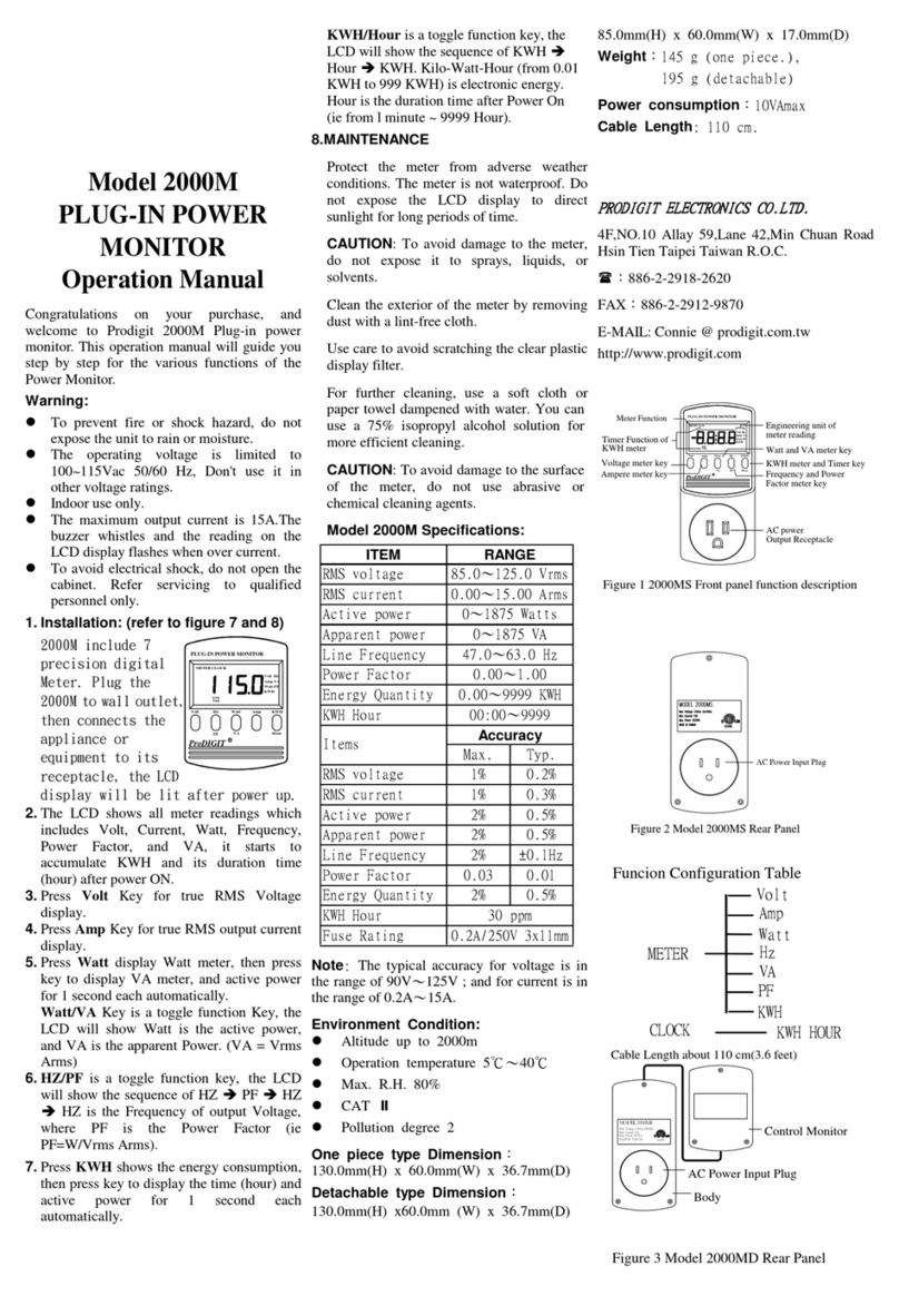
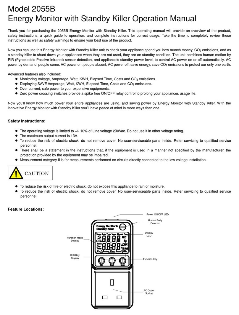
Prodigit 3330F User manual

3330F 系列
電子負載(抽取式模組)
使用手冊
深圳铨博科技整理出品
咨询热线:13823598552 QQ:54390204
经营产品:示波器、信号产生器、万用表、安规测试器、
LCR 电桥、功率计、失真仪、毫伏表、频谱分析仪、电源供应器、
电子负载、逻辑分析仪、变压器综合测试仪、电阻计、电池测试仪、
及各种常用仪器及专用配件。

S/N: 9003330F01 REV:A

Material Contents Declaration
(材料含量宣称)
(Part Name)
Note(注释):
1.Prodigit has not fully transitioned to lead-free solder assembly at this moment;However, most of the components used
are RoHS compliant.
(此刻,Prodigit 并非完全过渡到无铅焊料组装;但是大部份的元器件一至于 RoHS 的规定。)
2. The product is labeled with an environment-friendly usage period in years.
The marked period is assumed under the operating environment specified in the product specifications.
(产品标注了环境友好的使用期限制(年)。所标注的环境使用期限假定是在此产品定义的使用环境之下。)
Example of a marking for a 10 year period:
(例如此标制环境使用期限为 10 年)
Hazardous Substance (
有毒有害物质或元素
)
零件名称
铅(Pb) 汞(Hg)
镉(Cd)
六价铬
(Cr6+)
多溴联苯
(PBB)
多溴二苯醚
(PBDE)
PCBA
(印刷电路装配件) x ○ x ○ ○ ○
Electrical part not on
PCBA’s
未在 PCBA 上的电子零件 x ○ x ○ ○ ○
Metal parts
金属零件 ○ ○ ○ x ○ ○
Plastic parts
塑料零件 ○ ○ ○ ○ x x
Wiring
电线 x ○ ○ ○ ○ ○
Package
封装 x ○ ○ ○ ○ ○
对销售之日的所售产品,本表显示, PRODIGIT 供应链的电子信息产品可能包含这些物质。注意:在所售产品中可能会也可能不
会含有所有所列的部件。This table shows where these substances may be found in the supply chain of Prodigit electronic
information products, as of the date of sale of the enclosed product. Note that some of the component types listed above
may or may not be a part of the enclosed product. ○:表示该有毒有害物质在该部件所有均质材料中的含量均在 SJ/T 11363-
2006 标准规定的限量要求以下。○:Indicates that the concentration of the hazardous substance in all homogeneous
materials in the parts is below the relevant threshold of the SJ/T 113632006 standard. ×:表示该有毒有害物质至少在该部
件的某一均质材料中的含量超出 SJ/T 11363-2006 标准规定的限量要求。×: Indicates that the concentration of the
hazardous substance of at least one of all homogeneous materials in the parts is above the relevant threshold of the SJ/T
11363-2006 standard.

SAFETY SUMMARY
The following general safety precautions must be observed during all phases of operation, service, and
repair of this instrument. Failure to comply with these precautions or with specific warnings elsewhere in
this manual violates safety standards of design, manufacture, and intended use of the instrument.
PRODIGIT assumes no liability for the customer's failure to comply with these requirements.
GENERAL
This product is a Safety Class 1 instrument (provided with a protective earth terminal). The protective
features of this product may be impaired if it is used in a manner not specified in the operation
instructions.
ENVIRONMENTAL CONDITIONS
This instrument is intended for indoor use in an installation category I, pollution degree 2 environments. It
is designed to operate at a maximum relative humidity of 80% and at altitudes of up to 2000 meters.
Refer to the specifications tables for the ac mains voltage requirements and ambient operating
temperature range.
BEFORE APPLYING POWER
Verify that the product is set to match the available line voltage and the correct fuse is installed.
GROUND THE INSTRUMENT
This product is a Safety Class 1 instrument (provided with a protective earth terminal). To minimize shock
hazard, the instrument chassis and cabinet must be connected to an electrical ground. The instrument
must be connected to the ac power supply mains through a three conductor
power cable, with the third wire firmly connected to an electrical ground (safety ground) at the power
outlet. Any interruption of the protective (grounding) conductor or disconnection of the protective earth
terminal will cause a potential shock hazard that could result in personal injury.
FUSES
Only fuses with the required rated current, voltage, and specified type (normal blow, time delay, etc.)
should be used. Do not use repaired
Fuses or short circuited fuse holder. To do so could cause a shock or fire hazard.
DO NOT OPERATE IN AN EXPLOSIVE ATMOSPHERE.
Do not operate the instrument in the presence of flammable gases or fumes.
KEEP AWAY FROM LIVE CIRCUITS.
Operating personnel must not remove instrument covers. Component replacement and internal
adjustments must be made by qualified service personnel. Do not replace components with power cable
connected. Under certain conditions, dangerous voltages may exist even with the power cable removed.
To avoid injuries, always disconnect power, discharge circuits and remove external voltage sources
before touching components.
DO NOT SERVICE OR ADJUST ALONE.
Do not attempt internal service or adjustment unless another person, capable of rendering first aid and
resuscitation, is present.
DO NOT EXCEED INPUT RATINGS.
This instrument may be equipped with a line filter to reduce electromagnetic interference and must be
connected to a properly grounded receptacle to minimize electric shock hazard. Operation at line
voltages or frequencies in excess of those stated on the data plate may cause leakage currents in excess
of 5.0 mA peak.
DO NOT SUBSTITUTE PARTS OR MODIFY INSTRUMENT.
Because of the danger of introducing additional hazards, do not install substitute parts or perform any
unauthorized modification to the instrument. Return the instrument to a PRODIGIT ELECTRONICS Sales
and Service Office for service and repair to ensure that safety features are maintained.
Instruments which appear damaged or defective should be made inoperative and secured against
unintended operation until they can be repaired by qualified service personnel.

Company Name: PRODIGIT ELECTRONICS CO., LTD
Address: 8/F, No.88, Baojhong Rd., Sindian City, Taipei County, Taiwan, R.O.C.
Declares under sole responsibility that the product as originally delivered
Product Names: DC Electronic Loads
Model Numbers: 3330F、3332F、3336F、3300F、3302F、3305F
(And other customized products based upon the above)
Product Options:
This declaration covers all options and customized products based on the above products.
Complies with the essential requirements of the Low Voltage Directive 73/23/EEC and the EMC Directive
89/336/EEC (including 93/68/EEC) and carries the CE Marking accordingly.
EMC Information:
Class I a sample of the product has been assessed with respect to CE-marking according to the
Low
Voltage Directive (73/23/EEC& 93/68/EEC) and EMC Directive (89/336/EEC,92/31/EEC, & 93/68/EEC)
and Found to comply with the essential requirements of the Directives.
The Standard(s) used for showing the compliance and the full details of the results are given in the Test
Reports as detailed below:
Safety Information:
Safety standards following:
IEC 61010-1:2001 / EN 61010-1:2001
Jun 25, 2010
Date
The holder of the verification is authorized to use this verification in connection with the EC declaration Of
conformity according to the Directives. The CE marking may only be used if all releveant and
effective
EC Directives are complied with. Together with the manufacturer’s own documented production control,
The manufacturer (or his European authorized representative) can in his EC Declaration of Conformity
Verify compliance with the directives.
DECLARATION OF CONFORMITY

安全標誌
直流電源符號(DC)
交流電源符號(AC)
交流和直流電源符號
3相交流電源符號
機體接地符號
開(電源)
關(電源)
保險絲
高電壓警告符號 , 請參考手冊上所列的警告和注意說明,以避免人員受傷
危險標誌,可能會有高電壓存在,請避免接觸

3330F 系列電子負載使用手冊目錄
第一章、概 論 .............................................................................................................................................................................. 1
1-1 、整體說明 ..............................................................................................................................................................................
1-2 、3330F 系列電子負載之特性 .............................................................................................................................................
1-3 、附件 .......................................................................................................................................................................................
1-4 、規格 .......................................................................................................................................................................................
第二章、裝機 ...............................................................................................................................................................................11
2-1 、裝入及拔出 3330F 系列電子負載 .................................................................................................................................
2
2-2 、環境要求 ............................................................................................................................................................................
3
2-3 、注意安全標制列表如下 .........................................................................................................................................
.......... 13
2-4 、清潔方式 ............................................................................................................................................................................
3
2-5 、開機 .....................................................................................................................................................................................
3
2-6 、負載輸入端的連接............................................................................................................................................................ 13
2-7 、電子負載模組的操作流程
............................................................................................................................................... 14
第三章、操作 ...............................................................................................................................................................................15
3-1 、操作說明 ............................................................................................................................................................................
6
3-2 、負載輸入連接器與連接引線之考慮事項 ..................................................................................................................... 2
3-3 、保護特性 ............................................................................................................................................................................
4
第四章、應用 ...............................................................................................................................................................................35
4-1 、本地電壓檢知連接法 ...............................................................................................................................................
........ 35
4-2 、遠地電壓檢知連接法
....................................................................................................................................................... 36
4-3 、固定電流模式 (C.C. MODE) 的應用 ...............................................................................................................................
7
4-4 、固定電阻模式(C.R. MODE)的應用 ...................................................................................................................................
9
4-5 、固定電壓模式 (C.V. MODE)的應用 .................................................................................................................................
0
4-6 、固定功率模式(C.P. MODE)的應用 ...................................................................................................................................
1
4-7 、多組輸出之電源供應器與電子負載之連接 ................................................................................................................. 2
4-8 、並聯操作 ............................................................................................................................................................................
3
4-9 、最低工作電壓為零伏特之連接方式 ............................................................................................................................. 44
4-10、3330F 系列電子負載 OCP 、OPP 、SHORT 操作流程圖
.......................................................................................... 45
4-11 、電源供應器 OCP 測試 ...........................................................
........................................................................................ 46
4-12 、電源供應器 OPP 測試 ..............................................................................................................................................
..... 51
4-13 、電源供應器短路測試
..................................................................................................................................................... 56

圖形
圖 1-1 3330F CHA 0-80V / 0-60A 250W 電子負載功率圖 ................................................................................................. 1
圖 1-2 3330F CHB 0-80V/0-6A 50W 電子負載功率曲線圖 ............................................................................................... 1
圖 1-3 3332F 0-80V/0-24A 120W 電子負載功率曲線圖 .................................................................................................... 2
圖 1-4 3336F 0-80V/0-3A 40W 電子負載功率曲線圖 ........................................................................................................ 2
圖 1-5 固定電流模式特性圖 ................................................................................................................................................ 3
圖 1-6 固定電阻模式特性圖 ................................................................................................................................................ 3
圖 1-7 固定電壓模式特性圖 ................................................................................................................................................ 4
圖 1-8 固定功率模式特性圖 ................................................................................................................................................ 4
圖 1-9 動態負載模式特性圖 ................................................................................................................................................ 5
圖 1-10 回轉率(SLEW RATE)曲線圖 ..................................................................................................................................... 6
圖 2-1 負載輸入連接器 ....................................................................................................................................................... 11
圖 2-2 電子負載裝入及拔出 .............................................................................................................................................. 12
圖 2-3 3330F 系列電子負載操作流程圖 ........................................................................................................................... 14
圖 3-1 前面板圖 .................................................................................................................................................................... 15
圖 3-2 典型的 3330F 系列電子負載連接方式 ............................................................................................................... 28
圖 3-3 Y型端子連接圖 ......................................................................................................................................................... 32
圖 4-1 本地電壓檢知連接圖 .............................................................................................................................................. 35
圖 4-2 遠地電壓檢知連接圖 .............................................................................................................................................. 36
圖 4-3 固定電流操作模式之應用 ...................................................................................................................................... 37
圖 4-4 動態負載電流 ........................................................................................................................................................... 38
圖 4-5 固定電阻操作模式之應用 ...................................................................................................................................... 39
圖 4-6 固定電壓操作模式之應用 ...................................................................................................................................... 40
圖 4-7 固定功率操作模式之應用 ...................................................................................................................................... 41
圖 4-8 多組輸出電源供應器與電子負載之連接圖 ........................................................................................................ 42
圖 4-9 電子負載多組並聯之連接圖 ................................................................................................................................. 43
表格
表 1-1 3330F 系列電子負載規格表 ................................................................................................................................... 10
表 3-1 3330F CHA 起始狀態設定 .......................................................................................................................................
30
表 3-2 3330F CHB 起始狀態設定 ....................................................................................................................................... 30
表 3-3. 3332F CHA & CHB 起始狀態設定 ........................................................................................................................ 31
表 3-4. 3336F CHA & CHB 起始狀態設定 ........................................................................................................................ 31
表 3-5 標準電線電流容量 ................................................................................................................................................... 33

第一章、概 論
1-1 、整體說明
3330F 系列電子負載操作手冊 1
3330F 系列電子負載是用來測試評估直流電源供應器之規格特性,蓄電池之壽命特性以及電子元件之規
格等用途。
3330F 系列電子負載模組可工作於 3300F、3302F、3305F 機框上,工作於 3300F、3302F、3305F 機框
時,具有 150 組儲存/呼叫記憶,GPIB/RS232/USB/LAN 介面及面板手動操作均可動作,關於 3300F、
3302F、3305F 的機框請參考機框之操作手冊。
3300F、3302F、3305F 機框均可以安裝 1 至 4 組的 3330F 系列電子負載,其組合方式可以任意規格之組
合,主要為依應用時之需求規格而定,3330F CHA 250W 的工作區域曲線如圖 1-1 所示,其電壓與電流
之工作範圍分別為 0 -80V 及 0 -60A,3330F CHB 50W 的工作區域曲線如圖 1-2 所示,其電壓與電流
之工作範圍分別為 0 -80V 及 0 -6A。
圖 1-1 3330F CHA 0-80V / 0-60A 250W 電子負載功率圖
3330F CHB 50W 的工作區域曲線如圖 1-2 所示,其電壓與電流之工作範圍分別為 0-80V 及 0-6A。
圖 1-2 3330F CHB 0-80V/0-6A 50W 電子負載功率曲線圖

2 博計電子
3332F CHA & CHB 120W 的工作區域曲線如圖 1-3 所示,其電壓與電流之工作範圍分別為 0-80V 及 0-
24A。
圖 1-3 3332F 0-80V/0-24A 120W 電子負載功率曲線圖
3336F CHA & CHB 40W 的工作區域曲線如圖 1-4 所示,其電壓與電流之工作範圍分別為 0-80V 及 0-
3A。
圖 1-4 3336F 0-80V/0-3A 40W 電子負載功率曲線圖

3330F 系列電子負載操作手冊 3
3330F 系列 電子負載的工 作模式包含 、固定電流 (C.C.),固 定電阻 (C.R.), 固定電壓(C.V.),固定功率
(C.P),動態負載 (Dynamic Load)。於固定電流及固定功率模式動態負載時上升與下降負載電流斜率可以
分別設定控制,又於 3300F/3302F/3305F 背板上的類比輸入可依輸入訊號來控制所需之任意負載電流波
形。
固定電流模式 (C.C. Mode)
於固定電流工作模式時,3330F 系列電子負載所流入的負載電流係依所設定之電流值而與輸入電壓之大
小無關,如圖 1-5 所示,意即負載電流保持設定值不變。
CC
CURRENT SETTING
LOAD
CURRENT
固定電阻模式 (C.R. Mode)
INPUT VOLTAGE
圖 1-5 固定電流模式特性圖
V
於固定電阻工作模式時,3330F 系列電子負載所流入的負載電流係依據所設定負載電阻之大小而定,此
時負載電流與輸入電壓呈一正比例,如圖 1-6 所示,意即負載電阻保持設定值不變。
I
LOAD
CURRENT RESISTANCE
SETTING
INPUT VOLTAGE
圖 1-6 固定電阻模式特性圖
V
I

4 博計電子
固定電壓模式 (C.V. Mode)
於固定電壓工作模式時,3330F 系列電子負載所流入的負載電流係依據所設定之負載電壓而定,此時
負載電流的大小將會增加直到負載電壓等於設定值為止,如圖 1-7 所示,意即負載電壓保持設定值不
變。
I
VOLTAGE
LOAD
CURRENT
固定功率模式 (C.P Mode)
INPUT VOLTAGE
圖 1-7 固定電壓模式特性圖
V
於固定功率工作時,3330F 系列電子負載所流入的負載電流係依據所設定之功率之大小而定,此時負
載電流與輸入電壓的乘積等於功率設定值,如圖 1-8。
V
POWER
SETTING
0 I
動態負載 (Dynamic Load)
圖 1-8 固定功率模式特性圖
共有六個設定參 數來產生動態負載之脈 波電流波形,其分別為高 /低負載準位, 上升/下降負載 電流斜
率,高準位/低準位負載週期。
動態負載電流波形之定義和圖 1-9 所示,其中動態負載頻率及動態負載工作週期如下列式子所示:
Dynamic Frequency =
(THigh + TLow)
Duty Cycle = THigh
(THigh + TLow)
SETTING
1

3330F 系列電子負載操作手冊 5
LOAD
CURREN
T
I
FALL SLEW
RATE
HIGH LOAD
LOAD
LOW LOAD
LEVEL
V
RISE
SLEW RATE T
HIGH T
LOW
圖 1-9 動態負載模式特性圖
回轉率(Slew Rate):
3330F 系列回轉率僅適用於電流模式(CC Mode ),3330F 系列可控回轉率允許控制一負載電流由一
負載電流轉換電流轉換至另一負載電流以模擬待測物對此瞬態響應現象時的電壓降情形,或可稱為電源
供應器的瞬態響應測試。當負載電流從一個設定值轉換至另一個設定值的轉換時間是足夠大的時候實際
的轉換時間藉由回轉率是可以被計算出來的。
回轉率的計算是指電流變化的 10%到90%或者 90%到10%。
但是當負載電流從一個設定值轉換至另一個設定值的轉換時間比較小時,則會被限制在 3330F 系列的最
小轉換時間內,實際的轉換時間將大於等於預期的轉換時間。如圖 1-10
因此, 當要決定實際轉換時間時必須考慮到本機之最小轉換時間與回轉率
3330F 最小的轉換時間約為 30% 規格或者以上的負載變化( CCH - CCL > 60Ax 30%)
負載變化為規格的 100% 時, 回轉率在最小轉換時間到最大轉換時間會是最快的。
實際轉換時間會是最低的轉換時間,或總回轉時間(轉換除以回轉率),以較長者為準。
可利用下列公式計算最低轉換時間
最低轉換時間 =18A/ 設定的回轉率 (in amps/second)
7.2uS(18A/2.5) x 0.8(10%~90%) =5.76uS
最高的轉換時間 = 60A/設定的回轉率 (in amps/second)
24uS(60A/2.5) x 0.8(10~90%) = 19.2uS
例 : 使用者設定 CCH = 12A, CCL= 0A, 回轉率(Slew Rate) = 2.5A/uS, 期望的轉換時間為
4.8uS( 12/2.5)x 0.8(10%~90%) = 3.84uS
但實際量測到的轉換時間會在約最低轉換時間 5.76uS

6 博計電子
圖 1-10 回轉率(Slew Rate)曲線圖

1-2 、3330F 系列電子負載之特性
1.2.1 具有非常彈性組合之插入式電子負載模組及機框。
3330F 系列電子負載操作手冊 7
1.2.2
1.2.3
1.2.4
1.2.5
1.2.6
1.2.7
1.2.8
1.2.9
負載模組具備 CC、CR、CV、CP、 Dynamic 及 Short 等操作模式。
完全 RS-232 / GPIB / USB / LAN 控制之介面功能,包含負載狀態之設定及電壓電流表讀回。
雙高精確度/高解析度 16 位元電壓、電流錶與功率錶,並具有 GO/NG 判別能力。
內含寬範圍之脈波產生器,其中上昇/下降負載電流斜率可以獨立控制。
負載電流斜率可控制性:如負載準位改變,Load ON/OFF 切換,及電源供應器開機時電壓上升
瞬間等。以上負載電流之斜率可以依上升/下降負載電流斜率來控制設定。
短路負載測試功能,及短路電流量測功能。
自動電壓檢知能力,及可程式化 Vsense 開啟/關閉之設定功能。
保護功能包含過電壓、過電流、過功率、過溫度及逆向極性保護等。
1.2.10 數位式校正。
1.2.11 風扇轉速依負載功率自動調整。
1.2.12 配合機框具備 150 組記憶功能。
1-3 、附件
a 紅色大型香蕉插頭 4mm 2 PC
b 黑色大型香蕉插頭 4mm 2 PC
c 紅色小型香蕉插頭 2mm 2 PC
d 黑色小型香蕉插頭 2mm 2 PC
e 大型 Y型接頭 4 PC
f 3330F 系列使用手冊 1 PC

8 博計電子
1-3.1、附件使用說明

1-4 、規格
3330F 系列電子負載操作手冊 9
Model
Power
Current
Voltage
Min. Operating Voltage
Constant Current Mode
Range*1
Resolution
250W
0~60A
0~80V
0.8V @ 60A
0~6A/60A
0.1mA/1mA
3330F
50W
0~6A
0~80V
0.8V @ 6A
0~0.6A/6A
0.01mA/0.1mA
0~24A
0~80V
0.8V @ 24A
0~2.4A/24A
3332F
120Wx2
0.04mA/0.4mA
0~24A
0~80V
0.8V @ 24A
0~2.4A/24A
0~3A
0~80V
0.4V @ 3A
0~0.3A/3A
3336F
40Wx2
0.005mA/0.05mA
0~3A
0~80V
0.4V @ 3A
0~0.3A/3A
Accuracy
Constant Resistance Mode
Range
Resolution
Accuracy
Constant Voltage Mode
Range
Resolution
Accuracy
Constant Power Mode
Range
Resolution
Accuracy
Dynamic Mode -CC
Timing
Thigh & Tlow
Resolution
Accuracy
Slew rate
Resolution
Accuracy
Min. Rise Time
Current
Range
Resolution
Accuracy
Measurement
Voltage Read Back
Range (5 Digital)
Resolution
Accuracy
Current Read Back
Range (5 Digital)
Resolution
Accuracy
Power Read Back
Range (5 Digital)
Accuracy
Program mode(Mainframe)
Sequence No.
T1/T2 (Dwell)
GO/NG Check
Protections
Over Power
Over Current
Over Voltage
Over Temp.
Reverse polarity
± 0.1% (Setting + Range)
0.01335~1.335~80.1KΩ 0.1335~13.35~801KΩ
22.25μ Ω/12.484μ S 222.5μ Ω/1.2484μ S
0.2% OF (Setting + Range)
6V/80V 6V/80V
0.135mV/1.35mV
± 0.05% (Setting + Range)
25W(Imax.=6A)/250W 5W(Imax.=0.6A)/50W
0.417mW/4.17mW 0.084mW/0.84mW
± 0.5% (Setting + Range)
0.050~9.999 / 99.99 / 999.9 / 9999mS
0.001 / 0.01 / 0.1 / 1mS
1uS/10uS/100uS/1mS + 50ppm
4mA~250mA/uS 0.4mA~25mA/uS
40mA~2500mA/uS 4mA~250mA/uS
1mA/10mA 0.1mA/1mA
24uS(typical)
6/60A 0.6A/6A
0.1mA/1mA 0.01mA/0.1mA
± 0.1% (Setting + Range)
0~6V/81V 0~6V/81V
0.1mV/1.35mV
± 0.025% (Reading + Range)
0~6A/60A 0~0.6A/6A
0.1mA/1mA 0.01mA/0.1mA
± 0.1% (Reading + Range)
0~250W 0~50W
± 0.125% (Reading + Range)
105% of Rated Power
105% of Rated Current
105% of Rated Voltage
Yes
Yes
± 0.1% (Setting + Range)
0.0333~3.33~199.8KΩ 0.0333~3.33~199.8KΩ
55.55μ Ω /5μ S
0.2% OF (Setting + Range)
6V/80V 6V/80V
0.135mV/1.35mV
± 0.05% (Setting + Range)
12W(Imax.=2.4A)/120W 12W(Imax.=2.4A)/120W
0.2mW/2mW 0.2mW/2mW
± 0.5% (Setting + Range)
0.050~9.999 / 99.99 / 999.9 / 9999mS
0.001 / 0.01 / 0.1 / 1mS
1uS/10uS/100uS/1mS + 50ppm
1.6mA~100mA/uS 1.6mA~100mA/uS
16mA~1000mA/uS 16mA~1000mA/uS
0.4mA/4mA
(5% of setting) ± 10 uS
24uS(typical)
2.4/24A 2.4/24A
0.04mA/0.4mA
± 0.1% (Setting + Range)
0~6V/81V 0~6V/81V
0.1mV/1.35mV
± 0.025% (Reading + Range)
0~2.4A/24A 0~2.4A/24A
0.04mA/0.4mA
± 0.1% (Reading + Range)
0~120W 0~120W
± 0.125% (Reading + Range)
F1~9/16 Steps
0.1S~9.9S/Repeat 9999
Voltage/Current/Power
105% of Rated Power
105% of Rated Current
105% of Rated Voltage
Yes
Yes
± 0.1% (Setting + Range)
0.267~26.7~1602KΩ 0.267~26.7~1602KΩ
445μ Ω /0.6242μ S
0.2% OF (Setting + Range)
6V/80V 6V/80V
0.135mV/1.35mV
± 0.05% (Setting + Range)
4W(Imax.=0.3A)/40W 4W(Imax.=0.3A)/40W
0.067mW/0.67mW 0.067mW/0.67mW
± 0.5% (Setting + Range)
0.050~9.999 / 99.99 / 999.9 / 9999mS
0.001 / 0.01 / 0.1 / 1mS
1uS/10uS/100uS/1mS + 50ppm
0.2mA~12.5mA/uS 0.2mA~12.5mA/uS
2mA~125mA/uS 2mA~125mA/uS
0.05mA/0.5mA
24uS(typical)
0.3/3A 0.3A/3A
0.005mA/0.05mA
± 0.1% (Setting + Range)
0~6V/81V 0~6V/81V
0.1mV/1.35mV
± 0.025% (Reading + Range)
0~0.3A/3A 0~0.3A/3A
0.005mA/0.05mA
± 0.1% (Reading + Range)
0~40W 0~40W
± 0.125% (Reading + Range)
105% of Rated Power
105% of Rated Current
105% of Rated Voltage
Yes
Yes

10 博計電子
Interface(Mainframe)
RS-232
GPIB
USB
Ethernet
Remote Controller
Others
Load ON Voltage
Range
Resolution
Accuracy
Load OFF Voltage
Range
Resolution
Temperature Coefficient
Power
Operating Temperature*3
Dimension(HxWxD)
Weight
Safety & EMC
Dimension(HxWxD)
Weight
Safety & EMC
Optional
Optional
Optional
Optional
Optional
100ppm/℃(typical)
Supply from Mainframe
0~40℃
143 x 108 x 405 mm/5.6x4.3x15.9 inch
3.5 kg / 7.7 lbs
CE
143 x 108 x 405 mm/5.6x4.3x15.9 inch
3.5 kg / 7.7 lbs
CE
Optional
Optional
Optional
Optional
Optional
0.1~25.0V
0.1V
1% of Setting + 0.25V
0~25V
0.1mV/1.35mV
100ppm/℃(typical)
Supply from Mainframe
0~40℃
143 x 108 x 405 mm/5.6x4.3x15.9 inch
3.5 kg / 7.7 lbs
CE
143 x 108 x 405 mm/5.6x4.3x15.9 inch
CE
Optional
Optional
Optional
Optional
Optional
100ppm/℃(typical)
Supply from Mainframe
0~40℃
143 x 108 x 405 mm/5.6x4.3x15.9 inch
3.5 kg / 7.7 lbs
CE
143 x 108 x 405 mm/5.6x4.3x15.9 inch
CE
表 1-1 3330F 系列電子負載規格表
備註 1: 強制 Range II 功能只適用於 CC MODE
備註 2: Power F.S. = Vrange F.S. x Irange F.S.
備註 3 : 操作溫度的範圍是 0°C 40°C,所有的規格均於 25℃±5℃之下測試

第二章、裝機
3330F 系列電子負載操作手冊 11
本章中 討論關於 裝入或 拔出 3330F 系 列電子 負載模 組於 3300F/3302F/3305F 機框 的步驟與 方法,
3330F 系列電子負載於裝入 3300F/3302F/3305F 機框後可立即使用,並不需要任何之調整等步驟。
圖 2-1 負載輸入連接器

12 博計電子
2-1 、裝入及拔出 3330F 系列電子負載
除非 3300F/3302F/3305F 機框與 3330F 系列電子負載於訂購時分開購買,否則於出貨時 3330F 系列電
子負載將被裝置於 3300F/3302F/3305F 機框內一起出貨。
3330F 系列電子負載裝置於 3300F/3302F/3305F 機框時除面板手動操作外,尚可利用 3300F/3302F/3305F
機 框 上 , 的 GPIB 、 RS232 、 LAN 或 USB 等 遙 控 介 面 由 外 接 電 腦 以 軟 體 程 式 來 控 制 , 而 且
3300F/3302F/3305F 機框上各有 150 組儲存/記憶功能(註)。當您要將 3330F 系列電子負載模組裝入或拔
出 3300F 機框,重新組合時,請依下列之程序進行。
2.1.1 3330F 系列電子負載裝入步驟:
2.1.1.1 於裝入 3330F 系列電子負載前將 3300F/3302F/3305F 機框之電源開關關閉,以免損
壞模組及機框內部之元件。
2.1.1.2 對準欲裝入之機框內模組位置的上下導槽,將 3330F 系列電子負載置於此位置。
2.1.1.3 依圖 2-2 所示,將 3330F 系列電子負載推入機框內,並手持前面板的負載輸入端子
上向機框方向推,直到完全接合為止。
2.1.1.4 鎖緊位於前面板右下方的固定螺絲,螺絲之位置如圖 2-1 所示。
2.1.1.5 於所有 3330F 系列電子負載均裝入妥當之後,打開 3300F/3302F/3305F 機框之電
源。
2.1.2 拔出 3330F 系列電子負載之步驟:
2.1.2.1 首先將 3300F/3302F/3305F 機框之電源開關置於關閉 OFF 位置,否則介面電路可能
受損壞。
2.1.2.2 使用螺絲起子將模組面板右下角的螺絲卸下。
2.1.2.3 使用單指退出裝置將 3330F 系列模組退出。
圖 2-2 電子負載裝入及拔出
This manual suits for next models
2
Table of contents
Other Prodigit Measuring Instrument manuals
Popular Measuring Instrument manuals by other brands

Hilti
Hilti PSA 200 manual
AESSEAL
AESSEAL FLOWTRUE FTP-50-145 Installation, operation & maintenance manual
BRONKHORST
BRONKHORST EL-FLOW Prestige series instruction manual
Applent Instruments
Applent Instruments Anbai AT510PRO user manual
Milwaukee
Milwaukee MW101 user manual
Industrial Fiber Optics
Industrial Fiber Optics IF-RL05 Operator's manual
Panametrics
Panametrics HydroProII user manual
HP
HP E4418B user guide

Katronic Technologies
Katronic Technologies FLUXUS ADM 6725 Operating instruction

Kensington
Kensington KS-PH-221-DELUXE user manual
Extech Instruments
Extech Instruments 445580 user manual

GERMAN METERING
GERMAN METERING OP-735 user manual
