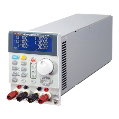
Prodigit 3270 Series User manual

3270 Series
AC/DC High power
Electronic Load
Operation manual
S/N:900327002REV:D

Material Contents Declaration
(材料含量宣称)
(Part Name)
零件名称
Hazardous Substance (
有毒有害物质或元素
)
铅(Pb) 汞(Hg)
镉(Cd)
六价铬
(Cr6+)
多溴联
苯(PBB)
多溴二苯醚
(PBDE)
PCBA
(印刷电路装配件)
x
○
x
○
○
○
Electrical part not on
PCBA’s
未在
PCBA
上的电子零件
x
○
x
○
○
○
Metal parts
金属零件
○
○
○
x
○
○
Plastic parts
塑料零件
○
○
○
○
x
x
Wiring
电线
x
○
○
○
○
○
Package
封装
x
○
○
○
○
○
对销售之日的所售产品
,
本表显示
, PRODIGIT
供应链的电子信息产品可能包含这些物质。注意
:
在所售产品中可能
会也可能不会含有所有所列的部件。This table shows where these substances may be found in the supply chain
of Prodigit electronic information products, as of the date of sale of the enclosed product. Note that some of the
component types listed above may or may not be a part of the enclosed product. ○:表示该有毒有害物质在该部
件所有均质材料中的含量均在SJ/T 11363-2006 标准规定的限量要求以下。○:Indicates that the concentration of
the hazardous substance in all homogeneous materials in the parts is below the relevant threshold of the SJ/T
113632006 standard. ×:表示该有毒有害物质至少在该部件的某一均质材料中的含量超出SJ/T 11363-2006 标准
规定的限量要求。×:Indicates that the concentration of the hazardous substance of at least one of all
homogeneous materials in the parts is above the relevant threshold of the SJ/T 11363-2006 standard.
Note(注释):
1.Prodigit has not fully transitioned to lead-free solder assembly at this moment;However, most of the
components used are RoHS compliant.
(此刻,Prodigit 并非完全过渡到无铅焊料组装;但是大部份的元器件一至于RoHS的规定。)
2. The product is labeled with an environment-friendly usage period in years.
The marked period is assumed under the operating environment specified in the product specifications.
(产品标注了环境友好的使用期限制(年)。所标注的环境使用期限假定是在此产品定义的使用环境之下。)
Example of a marking for a 10 year period:
(例如此标制环境使用期限为10年)

SAFETY SUMMARY
The following general safety precautions must be observed during all phases of operation, service,
and repair of this instrument. Failure to comply with these precautions or with specific warnings
elsewhere in this manual violates safety standards of design, manufacture, and intended use of the
instrument. PRODIGIT assumes no liability for the customer's failure to comply with these
requirements.
GENERAL
This product is a Safety Class 1 instrument (provided with a protective earth terminal). The protective
features of this product may be impaired if it is used in a manner not specified in the operation
instructions.
ENVIRONMENTAL CONDITIONS
This instrument is intended for indoor use in an installation category I, pollution degree 2 environments.
It is designed to operate at a maximum relative humidity of 80% and at altitudes of up to 2000 meters.
Refer to the specifications tables for the ac mains voltage requirements and ambient operating
temperature range.
BEFORE APPLYING POWER
Verify that the product is set to match the available line voltage and the correct fuse is installed.
GROUND THE INSTRUMENT
This product is a Safety Class 1 instrument (provided with a protective earth terminal). To minimize
shock hazard, the instrument chassis and cabinet must be connected to an electrical ground. The
instrument must be connected to the ac power supply mains through a three conductor
power cable, with the third wire firmly connected to an electrical ground (safety ground) at the power
outlet. Any interruption of the protective (grounding) conductor or disconnection of the protective earth
terminal will cause a potential shock hazard that could result in personal injury.
FUSES
Only fuses with the required rated current, voltage, and specified type (normal blow, time delay, etc.)
should be used. Do not use repaired
Fuses or short circuited fuse holder. To do so could cause a shock or fire hazard.
DO NOT OPERATE IN AN EXPLOSIVE ATMOSPHERE.
Do not operate the instrument in the presence of flammable gases or fumes.
KEEP AWAY FROM LIVE CIRCUITS.
Operating personnel must not remove instrument covers. Component replacement and internal
adjustments must be made by qualified service personnel. Do not replace components with power
cable connected. Under certain conditions, dangerous voltages may exist even with the power cable
removed. To avoid injuries, always disconnect power, discharge circuits and remove external voltage
sources before touching components.
DO NOT SERVICE OR ADJUST ALONE.
Do not attempt internal service or adjustment unless another person, capable of rendering first aid and
resuscitation, is present.
DO NOT EXCEED INPUT RATINGS.
This instrument may be equipped with a line filter to reduce electromagnetic interference and must be
connected to a properly grounded receptacle to minimize electric shock hazard. Operation at line
voltages or frequencies in excess of those stated on the data plate may cause leakage currents in
excess of 5.0 mA peak.
DO NOT SUBSTITUTE PARTS OR MODIFY INSTRUMENT.
Because of the danger of introducing additional hazards, do not install substitute parts or perform any
unauthorized modification to the instrument. Return the instrument to a PRODIGIT ELECTRONICS
Sales and Service Office for service and repair to ensure that safety features
are maintained.
Instruments which appear damaged or defective should be made inoperative and secured against
unintended operation until they can be repaired by qualified service personnel.

DECLARATION OF CONFORMITY
Company Name: PRODIGIT ELECTRONICS CO., LTD
Address:8F, No.88, Baojhong Rd., Sindian District, New Taipei City,Taiwan.
Declares under sole responsibility that the product as originally delivered
Product Names:AC/DC Electronic Loads
Model Numbers:3270, 3271, 3272, 3273, 3274
(And other customized products based upon the above)
Product Options:
Safety and EMC Information:
This declaration covers all options and customized products based on the above products.
Complies with the essential requirements of the Low Voltage Directive 2014/35/EU and the EMC
Directive 2014/30/EUand carries the CE Marking accordingly.
Safety standard:
Safety standards following:
IEC 61010-1:2010 / EN 61010-1:2011
EMC standard:
EN 61326-1:2006
EN 61326-2-1:2006
EN 55011:2009+A1:2010
EN 61000-3-2:2006+A1:2009+A2:2009
EN 61000-3-3:2008
EN 61000-4-2:2009
EN 61000-4-3:2006+A1:2008+A2:2010
EN 61000-4-4:2004+A1:2010
EN 61000-4-5:2006
EN 61000-4-6:2009
EN 61000-4-8:2010
EN 61000-4-11:2004
Oct, 18, 2017
Date
The holder of the verification is authorized to use this verification in connection with the EC declaration
of conformity according to the Directives. The CE marking may only be used if all releveant and
effective EC Directives are complied with. Together with the manufacturer’s own documented
production control, The manufacturer (or his European authorized representative) can in his EC
Declaration of Conformity Verify compliance with the directives.

SAFETY SYMBOLS
Direct current (DC)
Alternating current (AC)
Both direct and alternating
Three-phase alternating current
Off (Supply)
On (Supply)
Protective earth (ground)
Caution!Refer to this manual before using the meter.
Caution, risk of electric shock
CAT IV – Is for measurements performed at the source of the low-voltage
installation.
CAT III – Is for measurements performed in the building installation.
CAT II – Is for measurements performed on circuits directly connected to the low-
voltage installation.
CAT I – Is for measurements performed on circuits not directly connected to Mains.
Fuse

3270 series AC/DC load operation manual
Table of Contents
Chapter 1 Introduction ···························································································1
1-1. GENERAL DESCRIPTION ·············································································1
1-2. FEATURES ·························································································· 11
1-3. STANDARD ACCESSORIES ········································································ 11
1-4. OPTION ····························································································· 12
1-5. SPECIFICATIONS 1 ················································································· 12
1-6. SPECIFICATIONS 2 ················································································· 13
Chapter 2 Installation···························································································15
2-1 INSPECTION························································································· 15
2-2 CHECK LINE VOLTAGE ············································································ 15
2-3 FUSE EXCHANGE ·················································································· 15
2-4 GROUNDING REQUIREMENTS····································································· 16
2-5 ENVIRONMENTAL REQUIREMENTS······························································· 17
2-6 REPAIR······························································································ 17
2-7 CLEANING ·························································································· 17
2-8 POWER UP·························································································· 17
2-9 CONNECTION TO THE LOAD INPUT TERMINAL ON THE REAR PANEL························· 18
2-10 GPIB &RS232 CONNECTION OPTION··························································· 18
2-11 RS232 CONNECTION OPTION····································································· 18
2-12 GPIB CONNECTION OPTION ······································································ 19
2-13 USB CONNECTION OPTION ······································································· 19
2-14 LAN CONNECTION OPTION······································································· 19
2-15 I/O CONNECTION··················································································· 19
2-16 LOAD WIRE INDUCTANCE ········································································· 20
Chapter 3 Operation····························································································23
3-1. 3270 SERIES SIZE DESCRIPTION·································································· 23
3-2. 3270 SERIES PANEL DIAGRAM ···································································· 24
3-3. LCD DISPLAY DESCRIPTION:····································································· 25
3-4. 3270 SERIES OPERATING INSTRUCTIONS (1) ··················································· 74
3-5. 3270 SERIES SYSTEM OPERATING INSTRUCTIONS (3) ········································· 75
3-6. INITIAL SETTING OF 3270 SERIES LOAD ························································· 88
3-7. PROTECTION FEATURES··········································································· 91
Chapter 4 Remote control programming operation·····················································92
4-1. INTRODUCTION ···················································································· 92
4-2. THE SUMMARY OF RS232 INTERFACE AND COMMAND········································ 92
4-3. 3270 SERIES REMOTE CONTROL COMMAND LIST1 ··································· 94
4-4. 3270 SERIES REMOTE CONTROL COMMAND LIST2 ··································· 99
4-5. THE DESCRIPTION OF ABBREVIATION···························································104
4-6. REMOTE CONTROL COMMAND LANGUAGE DESCRIPTION····································104
4-7. REMOTE CONTROL COMMAND DESCRIPTION ··················································104
Chapter 5 Applications······················································································· 117
5-1. LOCAL SENSE CONNECTIONS ····································································117
5-2. REMOTE SENSE CONNECTIONS ··································································118
5-3. CONSTANT CURRENT MODE AND LIN MODE APPLICATION ··································119
5-4. CONSTANT RESISTANCE MODE APPLICATION··················································120
5-5. CONSTANT VOLTAGE MODE APPLICATION·····················································121
5-6. CONSTANT POWER MODE APPLICATION························································122

5-7. BATTERY DISCHARGE TEST APPLICATION······················································124
5-8. CURRENT PROTECTION COMPONENT TEST ·····················································127
5-9. AC RECTIFIED LOAD SIMULATION ······························································129
5-10. PARALLEL OPERATION ···········································································130
5-11. (INRUSH CURRENT) ··············································································131
5-12. POWER SUPPLY OCP TESTING ··································································132
5-13. POWER SUPPLY OPP TESTING···································································134
5-14. SHORT TESTING ·················································································136

Figures
Fig 1-1 3270 power contour ····················································································5
Fig 1-2 3271 power contour ····················································································5
Fig 1-3 3272 power contour ····················································································5
Fig 1-4 3273 power contour ····················································································6
Fig 1-5 3274 power contour ····················································································6
Fig 1-6 Constant Current mode················································································6
Fig 1-7 Constant Current mode················································································7
Fig 1-8 Constant Resistance mode···········································································7
Fig 1-9 Constant Voltage mode················································································8
Fig 1-10 Constant Power mode················································································8
Fig 1-11 Constant Current mode··············································································9
Fig 1-12 Constant Resistance mode ·········································································9
Fig 1-13 Constant Power mode··············································································10
Fig 1-14 Constant Voltage mode············································································10
Fig 2-1 3270 Series AC Input Connection ································································15
Fig 2-2 3270 Series fuse holder ·············································································16
Fig 2-3 3270 Series GPIB & RS232 Connection ························································18
Fig 2-4 3270 Series RS232 Rear panel ···································································18
Fig 2-5 3270 Series GPIB Rear panel ·····································································19
Fig 2-6 3270 Series USB Connection······································································19
Fig 2-7 3270 Series LAN Connection ······································································19
Fig 2-8 3270 Series I/O Connection ········································································19
Fig 2-9 Waveform example: Generate unstable oscillation···········································21
Fig 2-10 Length of wiring······················································································22
Fig 3-1 3270 Series SIZE description ······································································23
Fig 3-2 3270 Series Rear Panel ·············································································24
Fig 3-3 typical connection of 3270 series load module ················································71
Fig 3-4 typical connection of 3270 series load module ················································71
Fig 3-5 An equivalent circuit in terms of the current monitor ·········································72
Fig 3-6 (Correct) Connections to an oscilloscope·······················································73
Fig 3-7 (Wrong) Connections to an oscilloscope························································73
Fig 3-8 STORE (EDIT) MODE OPERATIONO FLOW-CHART······································85
Fig 3-9 TEST MODE OPERATION FLOW-CHA ························································87
Fig 4-1 RS232 INTERFACE CONNECTION OF REAR PANEL ····································93
Fig 5-1 Local voltage sense connections································································ 117
Fig 5-2 Remote voltage sense connections ···························································· 118
Fig 5-3 constant CURRENT & mode application···················································· 119
Fig 5-4 Constant Resistance mode Application························································ 120
Fig 5-5 Constant Voltage mode application····························································· 121
Fig 5-6 CONSTANT POWER MODE APPLICATION················································ 123
Fig 5-7 3270 series load parallel operation ····························································· 130
Fig 5-8 Inrush Current test at power on·································································· 131
Fig 5-9 Surge Current test when the appliance is connected ······································ 131

Tables
Table 1-1 3270 Series Specifications ······································································12
Table 1-1A 3270 Series Specification······································································14
Table 3-1 ··········································································································83
Table 3-2 AUTO SEQUENCE 3PH MODE can not be used command ···························83
Table 3-3 3PH MODE GLOB command···································································83
Table 3-4 3270 initialize ·······················································································88
Table 3-5 3271 initialize ·······················································································88
Table 3-6 3272 initialize ·······················································································89
Table 3-7 3273 initialize ·······················································································89
Table 3-8 3274 initialize ·······················································································90
Table 4-1 REMOTE CONTROL SETTING COMMAND SUMMARY·······························95
Table 4-2 REMOTE CONTROL QUERY COMMAND SUMMARY ·································96
Table 4-3 REMOTE CONTROL LIMIT COMMAND SUMMARY ····································96
Table 4-4 STAGE COMMAND SUMMARY·······························································97
Table 4-5 SYSTEM COMMAND SUMMARY·····························································97
Table 4-6 MEASURE COMMAND SUMMARY··························································98
Table 4-7 Auto sequence command list ···································································98
Table 4-1B REMOTE CONTROL SETTING COMMAND SUMMARY·····························99
Table 4-2B REMOTE CONTROL QUERY COMMAND SUMMARY ····························· 100
Table 4-3B REMOTE CONTROL LIMIT COMMAND SUMMARY ································ 101
Table 4-4B STAGE COMMAND SUMMARY··························································· 102
Table 4-5B SYSTEM COMMAND SUMMARY························································· 103
Table 4-6B MEASURE COMMAND SUMMARY······················································ 103
Table 4-8 GPIB COMMAND TERMINATOR ··························································· 104
Table 4-9 module for each series ········································································· 112
Table 4-10 register of PROT status······································································· 114
Table 4-11 MODEL NUMBER ············································································· 115

3270 Series Operation Manual 1
Chapter 1 Introduction
1-1. General description
5 digit V/A/W Meter,display the Voltage(Vrms, Vpeak, Vmax., Vmin)、Current (Irms,
Ipeak, Imax, Imin.),Watt, Voltampere (VA), Frequency Crest Factor、Power Factor,Total
Harmonic Distortion of Voltage(VTHD), Voltage Harmonic(VH)、Total Harmonic
Distortion of Current(ITHD), Current Harmonic(IH)
When Turbo ON, power and current increase 2 times
3270 Series is suitable for the step, square and sine wave of the AC Power device test,
Especially For the uninterruptible power supply UPS, Inverter, fuses, circuit breakers, power
Regulator AVR, Battery, AC / DC power supply / components ... and so on, absolutely is the
Best test solution in the market.

2PRODIGIT
•3270 LOAD Operating mode

3270 Series Operation Manual 3
The most complete measurement function
3270 series AC / DC electronic load has built-in 16-bit precision measurement circuit,
providing accurate measurement values, measuring items include voltage rms
(Vrms), current rms (Arms), watts (Watt), voltampere (VA), crest factor (CF), power
factor (PF), voltage total harmonic distortion (VTHD), voltage harmonics (VH), current total
harmonic distortion (ITHD), current Harmonics (IH), peak current (Ipeak), maximum ampere
(Amax), minimum ampere (Amin), maximum voltage (Vmax), and minimum voltage (Vmin).
In addition to these measurement functions, it also provides time measurement, such as UPS
back up time, fuses and circuit breakers’ trip or blow time and Off-line UPS transfer time.
Note*1:ms= milli - siemens = 1/kΩ
Note*2:The operating temperature range is 0 ~ 40 ℃, accuracy of this specification is 25 °
C ± 5 ° C

4PRODIGIT
•Parallel and three-phase control
3 phase Y connection
3 phase △connection

3270 Series Operation Manual 5
3270 Series AC/DC electronic load can be used to work with GPIB, RS232, USB or LAN
interface and panel manual operation can be made available. The work area of 3270 3750W
is as shown in Fig.1-1. The work scope of its voltage and current is 0-350Vrms and 0-
37.5Arms respectively.
The electronic load operating environment temperature is 0 ° C ~ 40 ° C, full power operation
for a period of time may produce OTP.
Fig 1-1 3270 power contour
The work area of 3271 2800W is as shown in Fig.1-2.
The work scope of its voltage and current is 0-350Vrms and 0-28Arms respectively.
Fig 1-2 3271 power contour
The work area of 3272 1875W is as shown in Fig.1-3.
The work scope of its voltage and current is 0-350Vrms and 0-28Arms respectively.
Fig 1-3 3272 power contour
350V
10V
37.5A
12.5A
3750W
Power Curve
Voltage
Current
100V
50V
25A37A
20V30V
10.7A
350V
10V28A8A
Voltage
Current
100V
50V
18.75A27.75A
20V30V
9.375A
2800W
Power Curve
350V
10V18.75A6.25A
1875W
Power Curve
Voltage
Current
100V
50V
12.5A 18.5A
20V30V
5.35A

6PRODIGIT
Fig 1-4 3273 power contour
Fig 1-5 3274 power contour
Complete AC and DC load modes
•AC load mode
1.1.1. CC Mode
With the operating mode of Constant Current, the 3270 series electronic load will sink a
current in accordance with the programmed value regardless of the input voltage (see
Fig.1-6).
Fig 1-6 Constant Current mode
Current Setting
350V
28A
3750W
Power Curve
Voltage
Current
133V
50V
18.6A
20V
10.7A
350V
18.75A8A
2800W
Power Curv
Voltage
Current
149V
50V
12.5A
20V

3270 Series Operation Manual 7
1.1.2. Linear C.C. Mode
During Linear C.C. mode, the load current input into 3270 Series High Power Electronic
Load depends on the current setting regardless of the input voltage, e.g., the current setting
remains unchanged. Please refer to Fig.1-7. The load input current signal will follow input
voltage signal, That is useful for step wave-form and square wave-form device.
Fig 1-7 Constant Current mode
1.1.3. CR Mode:
At Constant Resistance mode, the 3270 series Electronic Load will sink a current linearly
proportional to the load input voltage in accordance with the programmed resistance setting
(see Fig 1-8).
Fig 1-8 Constant Resistance mode
Current Setting
Resistance Setting

8PRODIGIT
1.1.4. CV Mode:
At Constant Voltage mode, the 3270 series Electronic Load will attempt to sink enough
current until the load input voltage reaches the programmed value (see Fig 1-9).
Fig 1-9 Constant Voltage mode
1.1.5. CP Mode:
At Constant Power mode, the 3270 series Electronic Load will attempt to sink load power
(load voltage * load current) in accordance with the programmed power. (See Fig 1-10).
Fig 1-10 Constant Power mode
Voltage Setting
Power Setting

3270 Series Operation Manual 9
•DC load mode
1.1.6. CC Mode
With the operating mode of Constant Current, the 3270 series electronic load will sink a
current in accordance with the programmed value regardless of the input voltage (see
Fig.1-11).
Fig 1-11 Constant Current mode
1.1.7. CR Mode
At Constant Resistance mode, the 3270 series Electronic Load will sink a current linearly
proportional to the load input voltage in accordance with the programmed resistance setting
(see Fig 1-12).
Fig 1-12 Constant Resistance mode
Resistance Setting
Current Setting

10 PRODIGIT
1.1.8. CP Mode:
At Constant Power mode, the 3270 series Electronic Load will attempt to sink load power
(load voltage * load current) in accordance with the programmed power. (See Fig 1-13).
Fig 1-13 Constant Power mode
1.1.9. CV Mode:
At Constant Voltage mode, the 3270 series Electronic Load will attempt to sink enough
current until the load input voltage reaches the programmed value (see Fig 1-14).
Fig 1-14 Constant Voltage mode
Voltage Setting

3270 Series Operation Manual 11
1-2. Features
The main features of the 3270 series of load are highlighted below.
1.2.1. Four meters can be displayed V/A/W Meter, display the Voltage (Vrms, Vpeak, Vmax.,
Vmin), Current (Irms, I Peak, Imax. Imin.) Watt, Voltampere (VA), Frequency, Crest
Factor, Power Factor, Total Harmonic Distortion of Voltage (VTHD), Voltage Harmonic
(VH), Total Harmonic Distortion of Current (ITHD), Current Harmonic (IH) Remote
Control via a choice of Computer interfaces.
1.2.2. AC / DC load with CC, Linear CC, CR, CV, CP and Rectifier Load mode
1.2.3. Frequency Range : DC, 40~440Hz
1.2.4. Crest factor adjustable range : 1.414~5.0
1.2.5. Power factor (PF) adjustable range: 0~1 lead or(-1~0)lag
1.2.6. Built-in test modes include UPS Efficiency, PV Inverter Efficiency, UPS Back-up time,
Battery Discharge time, UPS transfer time, Fuse / Breaker Trip / Non-Trip, short circuit
Simulation, OCP, OPP, etc.
1.2.7. Turbo mode, which can withstand up to twice the current (75A) and power (7.5KW)
Electronic load in a short time, the most suitable for Fuse / Breaker and AC power short
Circuit, OCP, OPP test.
1.2.8. Eight units parallel up to 90KW and three-phase △or Y load connection can be
Synchronized control by one master unit
1.2.9. Can be controlled by external voltage for CC, Linear CC, CR, CP, CV mode (Option)
1.2.10. Measure the fuse and circuit breaker trip or blow time
1.2.11. Measure the UPS OFF-Line transfer time(Transfer time)
1.2.12. Perform short circuit simulation(can set the short circuit time), OCP, OPP test
1.2.13. Over voltage warning, over current, over power, over temperature protection.
1.2.14. Optional interface: GPIB, RS232, USB, LAN.
1.2.15. 150 set Store/Recall memory.
1.2.16. Support on-load boot; at first set Load ON to support on-load boot, inverter or
Uninterruptible power supply is turned on directly with the set load current, used to verify
Whether the starter is stable when the Inverter is connected.
1.2.17. Supports the loading and unloading angle control; the loading and unloading angle
Control, the full range of 0-359 degrees can be set to verify whether the Inverter output
Voltage transient response is stable when the actual electrical plugging and unplugging,
And whether Overshoot/Undershoot is within the allowable range.
1.2.18. Support positive half-cycle or negative half-cycle loading; used to verify whether the
Inverter output voltage remains stable when the actual appliance has only positive half-
Cycle or negative half-cycle load current.
1.2.19. Supports SCR/TRIAC current phase modulation waveforms, 90 degree Trailing edge
And leading Edge.
1.2.20. Supports the Inrush Current of the power supply at startup and the Surge Current test
When the load is suddenly plugged in (Hot Plug-in).
1-3. Standard Accessories
a 3270 Series operation manual...................................1PCs
b Round terminal RVL1-4.............................................2PCs
c Round terminal RNYBS8-4........................................2PCs
d Terminal PTV1-12......................................................6PCs
e HD-DSUB 15pin MALE to MALE 150cm………….…1 PCs
Table of contents
Other Prodigit Measuring Instrument manuals
Popular Measuring Instrument manuals by other brands

Niigata seiki
Niigata seiki LEVELNIC DL-S3 DL-BW Operation manual

Olympus
Olympus USPM-RU-W Series Operation manual

OPTILAB
OPTILAB TWL-C-M Series user manual

Super Systems
Super Systems eFlo 2.0 Operation manual

Gossen MetraWatt
Gossen MetraWatt ENERGYMID EM2281 operating instructions

DigiTrak
DigiTrak Falcon F1 Operator's manual