Produal HDHFL User manual
USER GUIDE
HDHFL
V2.2 (22.08.2014)
1 (8)
Produal Oy Keltakalliontie 18, 48770 Kotka FINLAND Tel: +358 10 219 9100 / Fax: +358 5 230 9210 [email protected]i www.produal.com
Information is subject to change without prior notice.
COMMISSIONING
Selecting the transmitter position
The device can be installed in dry surroundings (IP20) by screws on the wall surface or on the standard flush mounting
box. The recommended installation height is 150…180 cm.
The device position should be selected carefully. All the error factors that can affect to the measurements should be
eliminated as well as possible. The following list defines the typical measurement error factors.
direct sun light
occupant proximity
air flow coming from windows or doors
air flow coming from ventilation nozzles
air flow coming from the flush mounting box
differential temperature caused by external wall
NOTE: The wireless network coverage affects also on the transmitter positioning. With the help of FLSER
commissioning tool, you can see the wireless network coverage and select the ideal transmitter positions inside the
network.
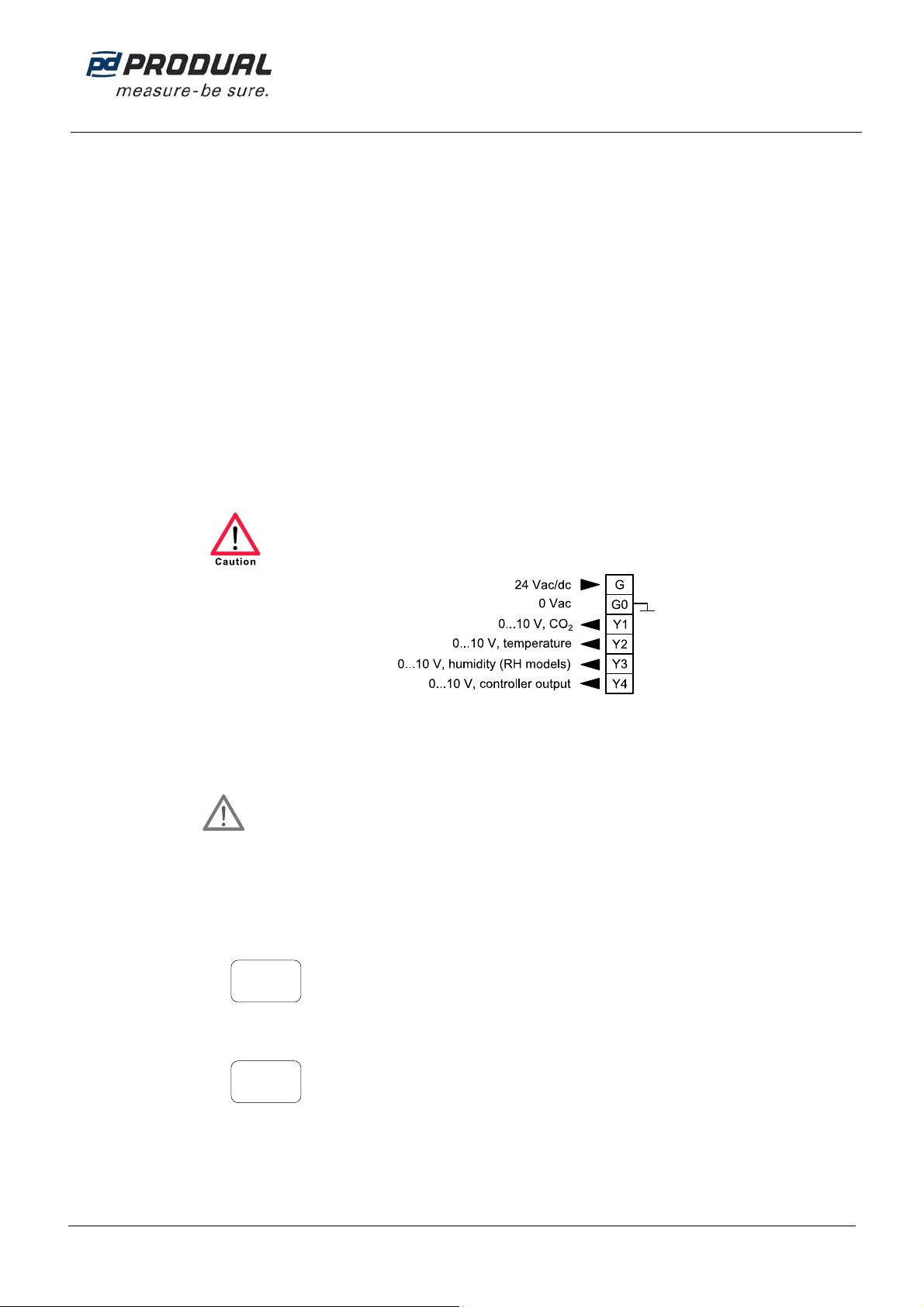
Wiring
Device wiring and commissioning can only be carried out by qualified professionals. Always make the
wirings while the power is switched off.
NOTE: CO2measurement causes a current peak to the supply voltage. This can produce an error to the analogue
outputs when using long and thin cables. It is recommended to increase the wire cross section area in long cable
situations (e.g. by using free pairs) to ensure reliable measurement signal.
Connecting to wireless network
IMPORTANT: The device wireless network settings are made by using either FLSER or ML-SER
commissioning tool. When the wireless settings are made with one tool, the other tool cannot be used to
change or check the wireless settings.
Connecting to wireless network by using FLSER tool
1. Disconnect the transmitter power supply.
2. Set the FLSER tool switch to the MID position.
3. Push the + and - buttons to select the FLTA base station master ID (MID) to which you are connecting the
transmitter.
4. Set the FLSER tool switch to the S-RID position.
5. Push the + and - buttons to select the sensor ID (SID) for the transmitter.
6. Push the OK button.
“Wait” message starts to flash on the FLSER tool display. You have now approximately 30 seconds to complete
the next step.
6
MID=
8
SID=

USER GUIDE
HDHFL
2 (8)
Produal Oy Keltakalliontie 18, 48770 Kotka FINLAND Tel: +358 10 219 9100 / Fax: +358 5 230 9210 [email protected]i www.produal.com
Information is subject to change without prior notice.
7. Connect the power supply.
“OK” flashes on the FLSER display. When the flashing stops, the transmitter is ready to start the communication
with the FLTA base station.
8. FLSER tool starts to display the communication signal strengths between the FLSER and transmitter.
The bigger number indicates the strength of the received signal sent by FLSER and the smaller number the
strength of received signal sent by the transmitter.
RSSI = Received Signal Strength Indication:
1…2 = poor
3…5 = satisfactory
6…9 = good
10. Go to the FLTA base station and check that the signal strengths are adequate.
11. Set the FLSER tool switch to the OFF position.
The transmitter starts to communicate with the FLTA base station.
Reading the transmitter information from FLTA base station
The transmitter information can be read from the FLTA base station in three ways:
From the display
Temperature
CO2level
Humidity (only in RH models)
Through the analogue outputs
Via Modbus
INDICATOR LIGHT FUNCTIONS
A. Green indicator light
B. Red indicator light
The indicator lights are on for 0.5 seconds during the device start-up.
The green indicator light flashes when the device sends information to the base station. The red indicator light turns on
when the message transmit to the base station fails 20 consecutive times.
56.0
6 RH%
720
6 LUX
21.0
6 TE°C
8
RSSI 9
USER GUIDE
HDHFL
3 (8)
Produal Oy Keltakalliontie 18, 48770 Kotka FINLAND Tel: +358 10 219 9100 / Fax: +358 5 230 9210 [email protected]i www.produal.com
Information is subject to change without prior notice.
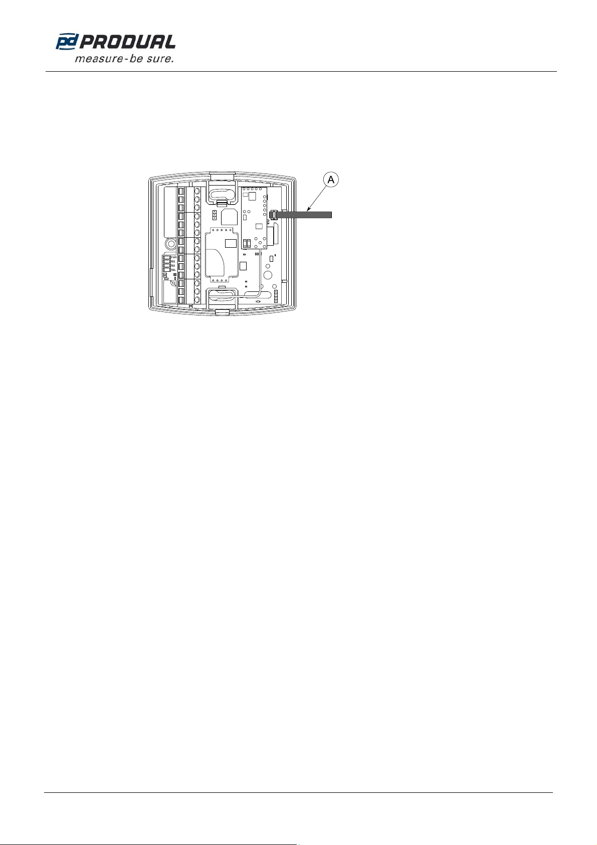
ML-SER TOOL
With the ML-SER tool you can change the device settings, controller and wireless network settings for example.
Connecting ML-SER tool to the device
1. Remove the display / HD-AL3 option.
2. Connect the ML-SER cable to the connector.
A. ML-SER cable
CO2measurement value shows on the ML-SER tool display.

USER GUIDE
HDHFL
4 (8)
Produal Oy Keltakalliontie 18, 48770 Kotka FINLAND Tel: +358 10 219 9100 / Fax: +358 5 230 9210 [email protected]i www.produal.com
Information is subject to change without prior notice.
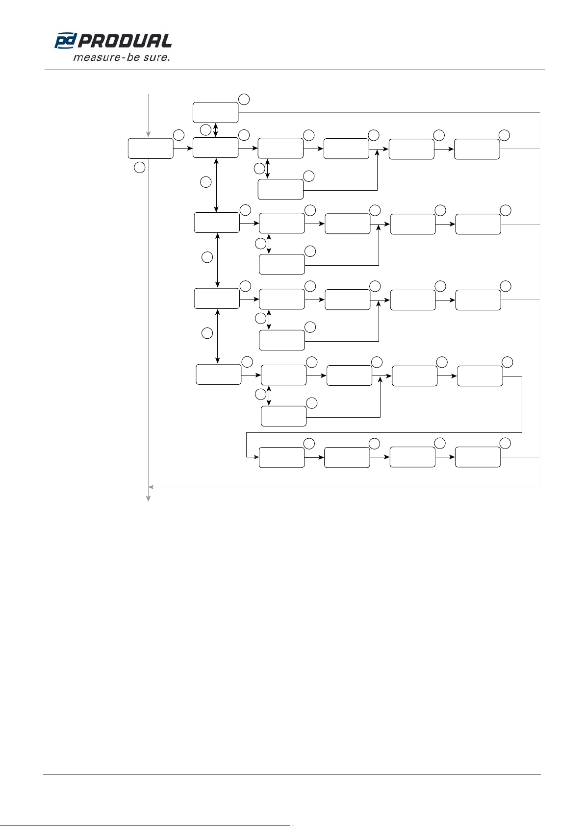
ML-SER menu
ML-SER menu opens by pressing the M button. The values can be changed with the ”+” and ”-” buttons. The menu is
device-specific and the content depends on the device and installed options.
The following menu structure contains the factory settings.
Measurement
Master ID (MID)
[1…63] Sensor ID (SID)
[OFF / 1…99]
CO
2
tuning
[±200 ppm] ABCLogiccalibration
[On / Off] Temperature measurement
tuning [±3,0 °C] Humiditymeasurement
tuning [±5 %RH]
Wireless
settings
menu
Calibration
menu
Controller
menu
AL3
menu
Info
menu
Controlmethod
[PI / P] Integration time
[50...5000 s] CO
2
set point
[400...10000ppm] CO
2
proportionalband
[100...10000]
Integration time
[50...5000 s] °C set point
[18...26 °C] ° C proportionalband
[1,0...32,0]
Integration time
[50...5000 s] %RH set point
[0...100 %] %RH proportional band
[10...100]
Integration time
[50...5000 s] CO
2
set point
[400...10000ppm] CO
2
proportionalband
[100...10000]
°C set point
[18...26 °C] ° C proportional band
[1,0...32,0] %RH setpoint
[0...100 %] %RH proportional band
[10...100]
Yellow indicator light illumination
point[400...10000 ppm] Red indicator lightillumination
point [400...10000 ppm]
Software
version Reset to factory settings
[no / yes]
Controlmethod
[PI / P]
Controlmethod
[PI / P]
Controlmethod
[PI / P]
M
M
M
OK OK OK
OK
M
Modbus ID
OK
+/-
+/-
+/-
CO2ppm
900
WIRELESS 1
MASTERID OFF
SENSOR ID
CALIBRATION
OK OK OK
Modbus ID
0
Offset:CO2ppm On
ABC-Logic 0.0
Offset: °C
OK
0
Offset: %RH
CONTROLLER
OFF
Cont
CO2
Cont
OK OK OK OK
Modbus ID
PI
Controlmode 300
Integr. time s 700
CO2Setpoint
OK
500
CO2Propor.band
P
Controlmode
OK
+/-
+/-
TEMPERATURE
Cont
OK OK OK OK
ModbusID
PI
Controlmode 300
Integr. time s 21.0
°CSetpoint
OK
2.0
°CPropor.band
P
Controlmode
OK
+/-
+/-
HUMIDITY
Cont
OK OK OK OK
ModbusID
PI
Controlmode 300
Integr. time s 50
%RHSetpoint
OK
50
%RHPropor.band
P
Controlmode
OK
+/-
MAXIMUM CTRL
Cont
OK OK OK OK
Modbus ID
PI
Controlmode 300
Integr. time s 700
CO2Setpoint
OK
500
CO2Propor.band
P
Controlmode
OK
OK
21.0
°CSetpoint
OK
2.0
°CPropor.band
OK
50
%RHSetpoint
OK
50
%RHPropor.band
M
OK OK OK
AL3 750
YELLOW 1250
RED
M
OK OK
Modbus ID
INFO 1.1.3
VERSION no
RESET
5 s
OK
OK
USER GUIDE
HDHFL
5 (8)
Produal Oy Keltakalliontie 18, 48770 Kotka FINLAND Tel: +358 10 219 9100 / Fax: +358 5 230 9210 [email protected]i www.produal.com
Information is subject to change without prior notice.
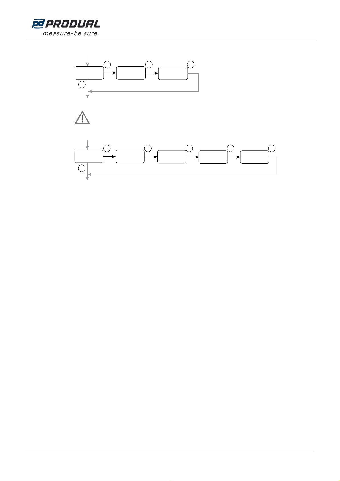
Wireless settings menu
Master ID (MID)
[1…63] Sensor ID (SID)
[OFF/ 1…99]
M
OK OK OK
Modbus ID
WIRELESS 1
MASTERID 1
SENSOR ID
Through the wireless settings menu you can set the master ID and sensor ID.
IMPORTANT: The device wireless network settings are made by using either FLSER or ML-SER
commissioning tool. When the wireless settings are made with one tool, the other tool cannot be used to
change or check the wireless settings.
Calibration menu
M
OK
CALIBRATION
OK OK OK
Modbus ID
0
Offset: CO2ppm On
ABC-Logic 0.0
Offset:°C
OK
0
Offset:%RH
CO2tuning
[±200 ppm] ABCLogiccalibration
[On / Off] Temperature measurement
tuning[±3,0 °C] Humidity measurement
tuning[±5 %RH]
All the measurements can be tuned through the calibration menu. The humidity tuning is available only in RH models.
The CO2value can be adjusted by 10 ppm steps.
The temperature value can be adjusted by 0.1 °C steps.
The humidity value can be adjusted by 1 % steps.
ML-SER tool display shows how much the current value is tuned.
USER GUIDE
HDHFL
6 (8)
Produal Oy Keltakalliontie 18, 48770 Kotka FINLAND Tel: +358 10 219 9100 / Fax: +358 5 230 9210 [email protected]i www.produal.com
Information is subject to change without prior notice.
Controller menu
Controlmethod
[PI / P] Integration time
[50...5000 s]
CO
2
set point
[400...10000 ppm]
CO
2
proportionalband
[100...10000]
Integration time
[50...5000s] °C set point
[18...26 °C] ° C proportional band
[1.0...32.0]
Integration time
[50...5000s] %RH setpoint
[0...100 %] %RH proportional band
[10...100]
Integration time
[50...5000 s]
CO
2
set point
[400...10000 ppm]
CO
2
proportionalband
[100...10000]
°C set point
[18...26 °C] ° C proportionalband
[1.0...32.0] %RH set point
[0...100 %] %RH proportional band
[10...100]
Controlmethod
[PI / P]
Controlmethod
[PI / P]
Controlmethod
[PI / P]
M
OK
+/-
+/-
+/-
CONTROLLER
OFF
Cont
CO2
Cont
OK OK OK OK
ModbusID
PI
Controlmode 300
Integr.time s 700
CO2Setpoint
OK
500
CO2Propor.band
P
Controlmode
OK
+/-
+/-
TEMPERATURE
Cont
OK OK OK OK
Modbus ID
PI
Controlmode 300
Integr. time s 21.0
°C Setpoint
OK
2.0
°C Propor.band
P
Controlmode
OK
+/-
+/-
HUMIDITY
Cont
OK OK OK OK
Modbus ID
PI
Controlmode 300
Integr. time s 50
%RHSetpoint
OK
50
%RHPropor.band
P
Controlmode
OK
+/-
MAXIMUM CTRL
Cont
OK OK OK OK
Modbus ID
PI
Controlmode 300
Integr. time s 700
CO2Setpoint
OK
500
CO2Propor.band
P
Controlmode
OK
OK
21.0
°C Setpoint
OK
2.0
°C Propor.band
OK
50
%RHSetpoint
OK
50
%RHPropor.band
OK
The control output can be controlled either according to a one measurement value or according to the maximum
selection of all values. Humidity related settings are only available in RH models.
The CO2values can be adjusted by 10 ppm steps.
The temperature values can be adjusted by 0,1 °C steps.
The humidity values can be adjusted by 5 % steps.

USER GUIDE
HDHFL
7 (8)
Produal Oy Keltakalliontie 18, 48770 Kotka FINLAND Tel: +358 10 219 9100 / Fax: +358 5 230 9210 [email protected]i www.produal.com
Information is subject to change without prior notice.
In the maximum selection control, the control output signal is formed according to the measurement that causes the
largest control signal value. The following situation is in the example figure:
Carbon dioxide concentration is 800 ppm
Temperature is 21,5 °C
Humidity is 55 %
AL3 menu
M
OK OK OK
AL3 750
YELLOW 1250
RED
Yellow indicator light illumination
point [400...10000 ppm] Red indicator light illumination
point [400...10000 ppm]
AL3 menu is available if HD-AL3 option is installed. The indicator light limits can be changed through the menu. The
hysteresis is 50 ppm.
Info menu
M
ModbusID
INFO 1.1.0
VERSION no
RESET?
OK
OK OK
5s
Software
version Reset to factory settings
[no/ yes]
You can check the device software version and reset the device to factory settings through the Info menu.
NOTE: If the wireless settings are set with the FLSER tool, resetting the factory settings doesn't return the wireless
settings to the factory defaults.

USER GUIDE
HDHFL
8 (8)
Produal Oy Keltakalliontie 18, 48770 Kotka FINLAND Tel: +358 10 219 9100 / Fax: +358 5 230 9210 [email protected]i www.produal.com
Information is subject to change without prior notice.
SELECTING THE MEASUREMENT INFORMATION TO BE VIEWED ON THE DISPLAY
The measurement values scroll on the N model display. The wanted value can be locked to view continuously by
pressing the S1 button. You resume to the scrolling view by pressing the S1 button again.
A. S1 button
CALIBRATION
If ABCLogic™ method is not in use, the device should be calibrated every 6-12 months. The recommended calibration
interval is 5 years even if the ABCLogic™ is in use.
ABCLOGICTM self-calibration feature
ABCLogic™ (Automatic Background Calibration Logic) is a patented self-calibration technique. ABCLogic™ method
eliminates the possible long term drift. ABCLogic™ method can be used when the CO2concentration drops at least
two times within a week to the level of approx. 400 ppm. Therefore the ABCLogic™ is effective in spaces that are not
continuously occupied.
ABCLogic™ can be deactivated in continuously occupied spaces.
Deactivating the ABCLogic™
The ABCLogic™ function can be deactivated by using the ML-SER tool.
Table of contents
Popular Measuring Instrument manuals by other brands

Schroeder Industries
Schroeder Industries HY-TRAX Operating and maintenance instructions

Cybertronix
Cybertronix Sentinel EFI-MFZ-50 user manual

Arkon
Arkon AgrimagP user guide

Rion
Rion UN-14 instruction manual

GAGEMAKER
GAGEMAKER CA-9001 Operation manual

Transducer Techniques
Transducer Techniques SSI Operator's manual

Endress+Hauser
Endress+Hauser RID14 Brief operating instructions

AESSEAL
AESSEAL FLOWTRUE FTP-50-145 Installation, operation & maintenance manual

Doza
Doza MKS-15D Snegir user manual

Vaisala
Vaisala HUMICAP HM70 user guide

Endress+Hauser
Endress+Hauser dosimass technical information

Rae
Rae ToxiRAE Pro user guide


