Produal KLH User manual

KLH - Room humidity transmitter/controller
User Guide
This user guide is for devices with the software version 1.3.6 or newer.

Published: 25.03.2022 2 (15)
Contents
1 Commissioning......................................................................... 3
1.1 Mounting room transmitters....................................................................................... 3
1.2 Wiring......................................................................................................................3
1.3 Selecting information to be viewed on the display.........................................................4
1.4 ML-SER tool............................................................................................................. 4
1.4.1 Connecting ML-SER tool to the device.............................................................. 4
1.4.2 ML-SER menu................................................................................................ 5
2 Modbus................................................................................... 12
2.1 Modbus properties................................................................................................... 12
2.2 Terminating Modbus.................................................................................................12
2.3 Modbus function codes.............................................................................................12
2.4 Modbus registers..................................................................................................... 12
2.4.1 Coils........................................................................................................... 13
2.4.2 Discrete inputs.............................................................................................13
2.4.3 Input registers............................................................................................. 13
2.4.4 Holding registers.......................................................................................... 14
Produal Oy | Keltakalliontie 18, FI 48770 Kotka, Finland | tel. +358 10 219 9100 | [email protected]
Information is subject to change without prior notice.
EN - 1132210ug

Published: 25.03.2022 3 (15)
1 Commissioning
1.1 Mounting room transmitters
The device can be installed in dry surroundings (IP20) by screws on the wall surface or on the
standard flush mounting box. The recommended installation height is 150...180 cm.
The device position should be selected carefully. All the error factors that can affect to the
measurements should be eliminated as well as possible. The following list defines the typical
measurement error factors.
• direct sun light
• occupant proximity
• air flow coming from windows or doors
• air flow coming from ventilation nozzles
• air flow coming from the flush mounting box
• differential temperature caused by external wall
1.2 Wiring
CAUTION: Device wiring and commissioning can only be carried out by qualified
professionals. Always make the wirings while the power is switched off.
PWR
RX
TX
REL
G24 Vac/dc, 2 VA supply
G0 0 V
Y1 Not in use.
Y2 Temperature output, 0...10 Vdc / 2...10 Vdc / 0...5 Vdc, < 2 mA
Y3 Humidity output / active potentiometer output, 0...10 Vdc / 2...10 Vdc / 0...5 Vdc, < 2 mA
Y4 Control output / active potentiometer output, 0...10 Vdc / 2...10 Vdc / 0...5 Vdc, < 2 mA
A+
B-
Modbus RTU, RS-485
Produal Oy | Keltakalliontie 18, FI 48770 Kotka, Finland | tel. +358 10 219 9100 | [email protected]
Information is subject to change without prior notice.
EN - 1132210ug
Published: 25.03.2022 4 (15)
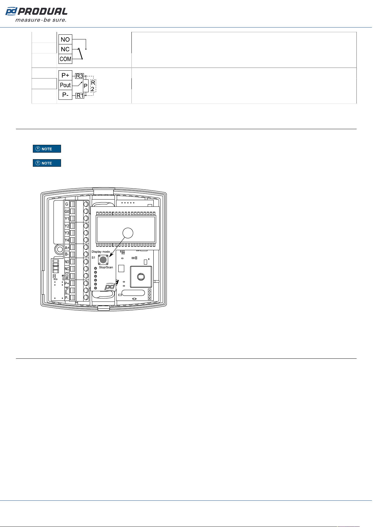
NO
NC
COM
Relay output, 24 Vac, 1 A
P+
Pout
P-
Passive potentiometer output.
1.3 Selecting information to be viewed on the display
The measurement values scroll on the N model display by default.
Note: In M models, the shown measurement information can be selected also via Modbus.
Note: When the potentiometer (PU models) is configured to change the controller setpoint,
the setpoint is shown on the display when the potentiometer is rotated.
• Press the S1 button to stop the scrolling to the currently displayed value.
PWR
RX
RX
REL
A
A. S1 button
• Press the S1 button again to start the scrolling.
1.4 ML-SER tool
1.4.1 Connecting ML-SER tool to the device
1. Open the cover.
2. Remove the display.
Produal Oy | Keltakalliontie 18, FI 48770 Kotka, Finland | tel. +358 10 219 9100 | [email protected]
Information is subject to change without prior notice.
EN - 1132210ug

Published: 25.03.2022 5 (15)
3. Connect the ML-SER cable to the display connector.
PWR
RX
RX
REL
A
A. ML-SER cable
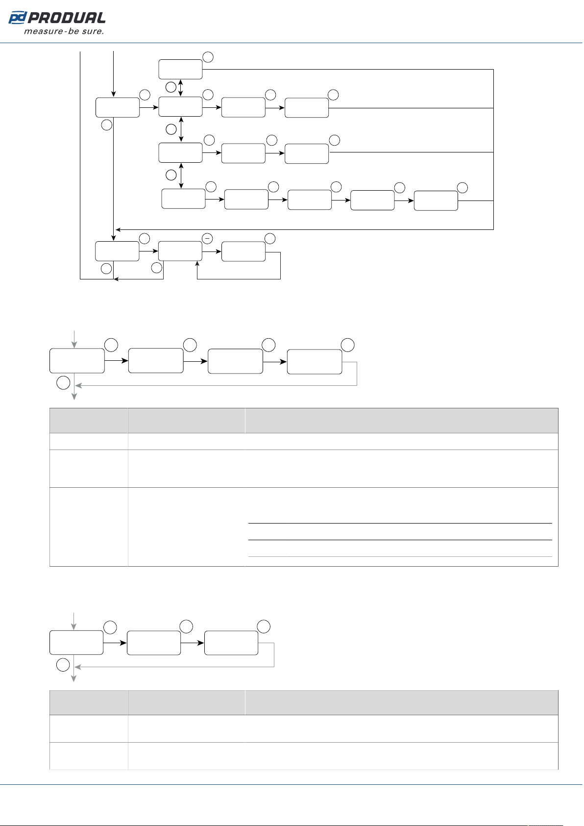
1.4.2 ML-SER menu
ML-SER menu opens by pressing the M button. The values can be changed with the ”+” and ”-”
buttons. The menu is device-specific and the content depends on the device and installed options.
The following menu structure contains the factory settings.
Produal Oy | Keltakalliontie 18, FI 48770 Kotka, Finland | tel. +358 10 219 9100 | [email protected]
Information is subject to change without prior notice.
EN - 1132210ug

Published: 25.03.2022 6 (15)
Measurement
Modbus address
[OFF / 1…247]
Modbus speed
[9.6 / 19.2 / 38.4]
Parity bit
[None / Even / Odd]
Controller
menu
Integration time
[50...5000 s]
°C set point
[0...50 °C]
° C proportional band
[1.0...32.0]
Integration time
[50...5000 s]
%RH set point
[0...100 %]
%RH proportional band
[10...100]
Integration time
[50...5000 s]
%RH set point
[0...100 %]
%RH proportional band
[10...100]
Control method
[PI / P]
Control method
[PI / P]
Control method
[PI / P]
OK
Modbus-
valikko
Kalibrointi-
valikko
Modbus
menu
Calibration
menu
Output
menu
Output scaling
[0-10V / 2-10V / 0-5V]
Controller output direction
[Direct / Reversed]
Fixed output
[100 / 75 / 50 / 25 / 0 %]
M
M
M
OK OK OK OK
OK
M
Modbus ID
OK
ppm
900
COMMUNICATIONS
1
MODBUS ID
9.6
Baud rate (k)
n
Parity
CALIBRATION
OK
CONTROLLER
OFF
Cont
CO2
Cont
TEMPERATURE
Cont
OK OK OK OK
Modbus ID
PI
Control mode
300
Integr. time s
21.0
°C Setpoint
OK
2.0
°C Propor. band
P
Control mode
OK
HUMIDITY
Cont
OK OK OK OK
Modbus ID
PI
Control mode
300
Integr. time s
50
%RH Setpoint
OK
50
%RH Propor. band
P
Control mode
OK
MAXIMUM CTRL
Cont
OK OK OK OK
Modbus ID
PI
Control mode
300
Integr. time s
OK
P
Control mode
OK
OK
OK
50
%RH Setpoint
50
%RH Propor. band
OK
M
OK OK
Modbus ID
OUTPUT
0-10V
Y1-Y4 range
OK
Direct
Output mode
OK
OFF
Fixed output
OK
100%
Fixed output
OK
12h
Deactivation
Temperature measurement
tuning [±3.0 °C]
Humidity measurement
tuning [±5 %RH]
0.0 (22.6)
Offset: °C
0 (30)
Offset: %RH
+/-
+/-
+/-
+/-
+/-
+/-
°C set point
[0...50 °C]
° C proportional band
[1.0...32.0]
21.0
°C Setpoint
2.0
°C Propor. band
Potentiometer
menu
2
°C set point center
[10...30 °C]
%RH set point low limit
[0...100 %]
%RH set point high limit
[0...100 %]
OK
POTENTIOMETER
OK
M
Y4
POT USAGE
OK
Y3
POT USAGE
OK
OFF
POT USAGE
+/-
+/-
OK
TE-SP
POT USAGE
+/-
OK
TE-SP CENTER °C
21.0
OK
RH-SP
POT USAGE
+/-
OK
RH-SP MIN
40
OK
RH-SP MAX
60
+/-
The diagram continues on the next page.
Produal Oy | Keltakalliontie 18, FI 48770 Kotka, Finland | tel. +358 10 219 9100 | [email protected]
Information is subject to change without prior notice.
EN - 1132210ug
Published: 25.03.2022 7 (15)
Relay
menu
Info
menu
Software
version
Reset to factory settings
[no / yes]
M
OK
RELAY
M
OK OK
Modbus ID
INFO
1.0.0
VERSION
no
RESET?
5 s
OK
OFF
Relay
OK OK OK
Modbus ID
OK OK OK
Modbus ID
ALL
Relay
OK OK OK
OK
OK OK
Hysteresis
[0...50 %]
Relay set point
[0...100 %]
Modbus ID
50
RelON %RH
5
Hysteresis %RH
+/-
+/-
+/-
Hysteresis
[0...20 °C]
Relay set point
[0...50 °C]
TEMPERATURE
Relay 23.0
RelON °C
2.0
Hysteresis °C
Hysteresis
[0...50 %]
Relay set point
[0...100 %]
HUMIDITY
Relay 50
RelON %RH
5
Hysteresis %RH
Hysteresis
[0...20 °C]
Relay set point
[0...50 °C]
23.0
RelON °C
2.0
Hysteresis °C
1.4.2.1 Communication menu
Communication menu is available in M models.
M
OK OK OK OK
Modbus ID
COMMUNICATIONS
1
MODBUS ID
9.6
Baud rate (k)
n
Parity
Parameter Available values Description
MODBUS ID OFF / 1...247 Modbus address.
Baud rate (k) 9.6 / 19.2 / 34.8 /
56.0 / 57.6 / 76.8 /
115.2
Modbus speed (kbit/s).
Parity n / E / O Parity bit.
nNone
EEven
OOdd
1.4.2.2 Calibration menu
All the measurements can be tuned through the calibration menu.
M
OK
CALIBRATION
OK
0.0 (22.6)
Offset: °C
OK
0 (30)
Offset: %RH
Parameter Available values Description
Offset °C -3.0...3.0 Temperature measurement tuning. The value can be adjusted by
0.1 °C steps.
Offset %RH -5...5 Humidity measurement tuning, RH models. The value can be
adjusted by 1 % steps.
Produal Oy | Keltakalliontie 18, FI 48770 Kotka, Finland | tel. +358 10 219 9100 | [email protected]
Information is subject to change without prior notice.
EN - 1132210ug

Published: 25.03.2022 8 (15)
ML-SER tool display shows how much the current value is tuned. The measured value is shown in
brackets after the tuning value.
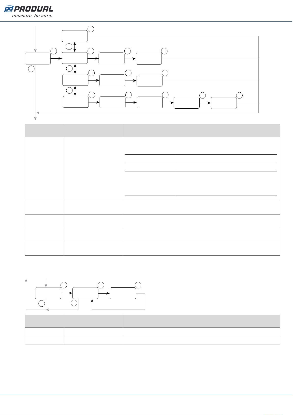
1.4.2.3 Output menu
You can change the output scaling of all outputs and the controller output direction through the output
menu. Also, the fixed controller output value and duration can be selected through the menu.
M
OK OK
Modbus ID
0-10V
Y1-Y4 range
OK
Direct
Output mode
OK
OFF
Fixed output
OK
100%
Fixed output
+/-
OK
12h
Deactivation
OUTPUT
Parameter Available values Description
Y1-Y4 range 0-10V / 2-10V / 0-5V Output scaling.
Output mode Direct / Reversed Controller output direction.
Fixed output OFF / 100% / 75% /
50% / 25% / 0%
Fixed output.
Deactivation 6h / 12h / 24h /
MANUAL
Fixed output deactivation timer.
1.4.2.4 Controller menu
The control output can be controlled either according to a one measurement value or according to the
maximum selection of all values.
M
OK
CONTROLLER
OFF
Cont
OK OK OK OK
Modbus ID
PI
Control mode
300
Integr. time s
21.0
°C Setpoint
OK
P
Control mode
OK
HUMIDITY
Cont
OK OK OK OK
Modbus ID
PI
Control mode
300
Integr. time s
50
%RH Setpoint
OK
P
Control mode
OK
MAXIMUM CTRL
Cont
OK OK OK
Modbus ID
PI
Control mode
300
Integr. time s
P
Control mode
OK
OK
21.0
°C Setpoint
OK
2.0
°C Propor. band
OK
50
%RH Setpoint
OK
OK
+/-
+/-
+/-
+/-
+/-
+/-
TEMPERATURE
Cont
50
%RH Propor. band
50
%RH Propor. band
2.0
°C Propor. band
Produal Oy | Keltakalliontie 18, FI 48770 Kotka, Finland | tel. +358 10 219 9100 | [email protected]
Information is subject to change without prior notice.
EN - 1132210ug

Published: 25.03.2022 9 (15)
Parameter Available values Description
Cont OFF / TEMPERATURE /
HUMIDITY / MAXIMUM
CTRL
Controlled value.
OFF Controller off
TEMPERATURE Temperature
HUMIDITY Relative humidity, RH models
MAXIMUM CTRL Maximum selection control. See more
details after the table.
Control mode P / PI Control method.
Integr. time s 50...5000 Integration time (s).
°C Setpoint 0...50.0 Set point for temperature (°C). The value can be adjusted by 0,1 °C
steps.
°C Propor. band 1.0...32.0 Proportional band for temperature (°C). The value can be adjusted
by 0,1 °C steps.
%RH Setpoint 0...100 Set point for humidity (%rH), RH models. The value can be adjusted
by 5 % steps.
%RH Propor.
band
10...100 Proportional band for humidity (%rH), RH models. The value can be
adjusted by 5 % steps.
In the maximum selection control, the control output signal is formed according to the measurement
that causes the largest control signal value. The following situation is described in the example figure:
• Temperature is 21.5 °C.
• Relative humidity is 55 %.
5
10
TE [°C]
Control output [V]
0
°C Setpoint
e.g. 21.0 °C
21.5 °C
Temperature = 3 V
Humidity = 4 V Control output = 4 V
5
10
RH [%]
Control output [V]
0
%RH Setpoint
e.g. 50 %
55 %
1.4.2.5 Potentiometer menu
Potentiometer menu is available in PU models. You can select the potentiometer output connector
and disable the potentiometer through the menu. You can also set the potentiometer for the set point
adjustment purposes. The potentiometer is connected to the Y4 output as factory setting.
Note: The set point that is adjusted with the potentiometer cannot be adjusted via
Modbus.
Produal Oy | Keltakalliontie 18, FI 48770 Kotka, Finland | tel. +358 10 219 9100 | [email protected]
Information is subject to change without prior notice.
EN - 1132210ug

Published: 25.03.2022 10 (15)
OK
POTENTIOMETER
OK
M
Y4
POT USAGE
OK
Y3
POT USAGE
OK
+/-
+/-
OK
TE-SP
POT USAGE
+/-
OK
TE-SP CENTER °C
21.0
OK
RH-SP
POT USAGE
+/-
OK
RH-SP MIN
40
OK
RH-SP MAX
60
OFF
POT USAGE
Parameter Available values Description
POT USAGE OFF / Y3 / Y4 / TE-SP /
RH-SP
Controlled value.
OFF Potentiometer is not in use.
Y3 Potentiometer output is Y3.
Y4 Potentiometer output is Y4.
Note: You have to set the controller
off, if the potentiometer is configured
to Y4 output.
TE-SP Potentiometer is used to set the temperature
setpoint. The potentiometer adjustment range is
±3 °C around the set point centre.
RH-SP Potentiometer is used to set the humidity
setpoint.
TE-SP CENTER
°C
10.0...30.0 °C Temperature setpoint centre. The value can be adjusted by 0.1 °C
steps.
RH-SP MIN 0...100 % Humidity setpoint range, low limit. The value can be adjusted by
5 % steps.
RH-SP MAX 0...100 % Humidity setpoint range, high limit. The value can be adjusted by
5 % steps.
1.4.2.6 Relay menu
Relay menu is available in R models. The relay switching point and hysteresis can be changed through
the menu.
Produal Oy | Keltakalliontie 18, FI 48770 Kotka, Finland | tel. +358 10 219 9100 | [email protected]
Information is subject to change without prior notice.
EN - 1132210ug
Published: 25.03.2022 11 (15)
M
OK
RELAY
+/-
OFF
Relay
OK OK OK
OK OK OK
Modbus ID
ALL
Relay
OK OK OK
OK
OK OK
+/-
+/-
TEMPERATURE
Relay 23.0
RelON °C
2.0
Hysteresis °C
HUMIDITY
Relay 50
RelON %RH
5
Hysteresis %RH
23.0
RelON °C
2.0
Hysteresis °C
50
RelON %RH
5
Hysteresis %RH
Parameter Available values Description
Relay OFF / TEMPERATURE /
HUMIDITY / ALL
Relay control value.
OFF Relay not in use.
TEMPERATURE Temperature.
HUMIDITY Relative humidity.
ALL All measurement values. When the relay is
controlled according to the all values, the
relay activates when one measured value
exceeds the set point.
RelON °C 0...50.0 Set point for temperature (°C). The value can be adjusted by 0,1 °C
steps.
Hysteresis °C 0.0...20.0 Hysteresis for temperature (°C). The value can be adjusted by
0,1 °C steps.
RelON %RH 0...100 Set point for humidity (%rH). The value can be adjusted by 5 %
steps.
Hysteresis %RH 0...50 Hysteresis for humidity (%rH). The value can be adjusted by 1 %
steps.
1.4.2.7 Info menu
You can check the device software version and reset the device to factory settings through the menu.
M
Modbus ID
INFO
X.X.X
VERSION
OK
OK OK
5 s
no
RESET?
Parameter Available values Description
VERSION X.X.X Device software version.
RESET? no / yes Reset to factory settings.
Produal Oy | Keltakalliontie 18, FI 48770 Kotka, Finland | tel. +358 10 219 9100 | [email protected]
Information is subject to change without prior notice.
EN - 1132210ug
Published: 25.03.2022 12 (15)
2 Modbus
2.1 Modbus properties
Protocol RS-485 Modbus RTU
Bus speed 9600*/14400/19200/38400/57600/115200 bit/s
Data bits 8
Parity none*/odd/even
Stop bits 1
Modbus ID 1*
Unit load 1/4 UL
* factory setting
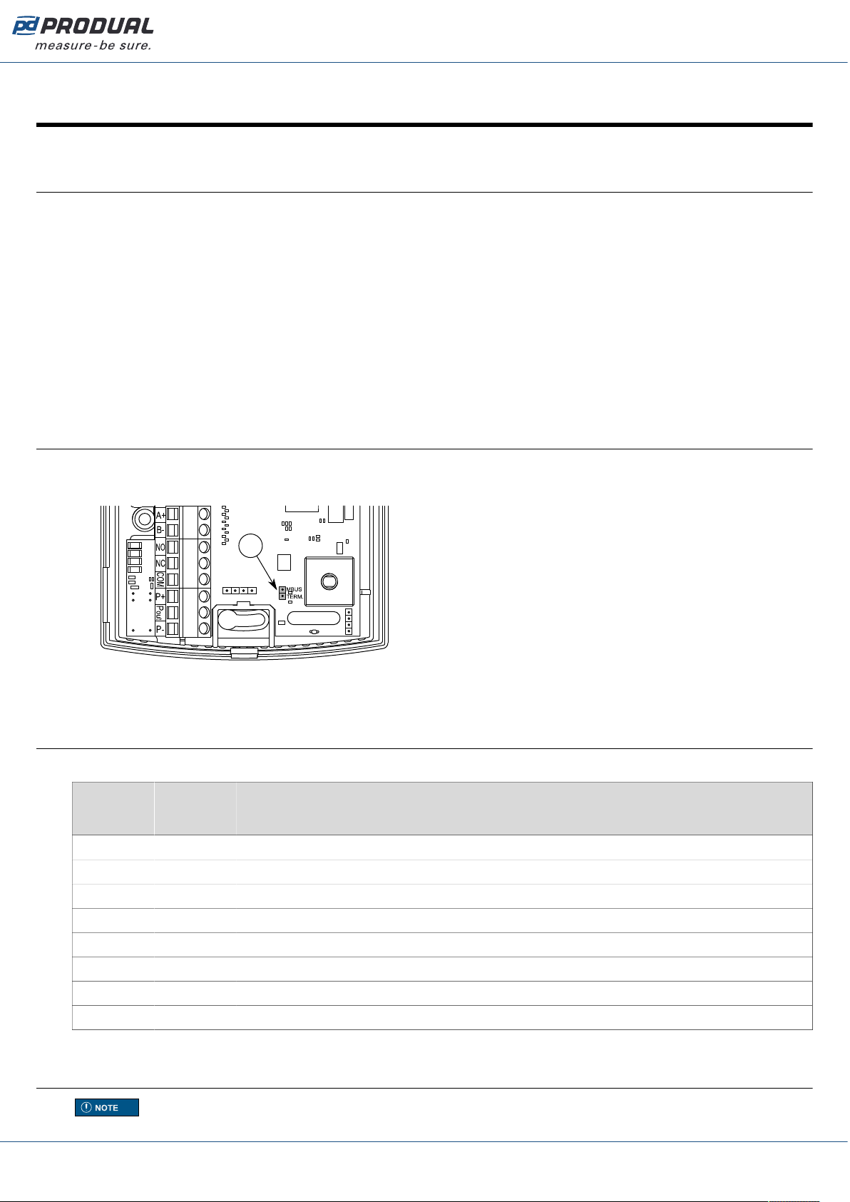
2.2 Terminating Modbus
1. Open the cover.
2. Place the termination jumper.
PWR
RX
RX
REL
A
A. Termination jumper
2.3 Modbus function codes
The device supports the following Modbus function codes.
Decimal Hexa-
decimal
Function
1 0x01 Read Coils
2 0x02 Read Discrete Inputs
3 0x03 Read Holding Registers
4 0x04 Read Input Registers
5 0x05 Write Single Coil
6 0x06 Write Single Register
15 0x0F Write Multiple Coils
16 0x10 Write Multiple Registers
2.4 Modbus registers
Note: If you try to write a parameter value that is beyond the parameter value range, the
value will be replaced by the nearest acceptable value.
Produal Oy | Keltakalliontie 18, FI 48770 Kotka, Finland | tel. +358 10 219 9100 | [email protected]
Information is subject to change without prior notice.
EN - 1132210ug

Published: 25.03.2022 13 (15)
Example:
1. The register value range is -500…500.
2. You try to write the value 600 to the register.
3. The value 500 is written to the register.
2.4.1 Coils
Regis-
ter
Parameter description Data type Values Range Default
1 Y1 output overdrive activation Bit 0 - 1 0. Off
1. On
0
2 Y2 output overdrive activation Bit 0 - 1 0. Off
1. On
0
3 Y3 output overdrive activation Bit 0 - 1 0. Off
1. On
0
4 Y4 output overdrive activation Bit 0 - 1 0. Off
1. On
0
5 Relay overdrive activation Bit 0 - 1 0. Off
1. On
0
6 Relay overdrive Bit 0 - 1 0. Off
1. On
0
7 Controller output direction Bit 0 - 1 0. Direct
1. Reversed
0
2.4.2 Discrete inputs
Register Parameter description Data type Values Range
10001 Relay status Bit 0 - 1 0. Off
1. On
2.4.3 Input registers
Register Parameter description Data type Values Range
30001 Not in use S16 - -
30002 Temperature measurement S16 0...500 0.0...50.0 °C
30003 Humidity measurement S16 0...100 0...100 %rH
30004 Y1 output voltage U16 0...1000 0.00…10.00 V
30005 Y2 output voltage U16 0...1000 0.00…10.00 V
30006 Y3 output voltage U16 0...1000 0.00…10.00 V
30007 Y4 output voltage U16 0...1000 0.00…10.00 V
30008 Active potentiometer value U16 0...1000 0.00…10.00 V
30009 Active potentiometer setpoint value U16 variable variable
Produal Oy | Keltakalliontie 18, FI 48770 Kotka, Finland | tel. +358 10 219 9100 | [email protected]
Information is subject to change without prior notice.
EN - 1132210ug

Published: 25.03.2022 14 (15)
2.4.4 Holding registers
Regis-
ter
Parameter description Data type Values Range Default
40001 Y1 output overdrive S16 0...1000 0...10.00 V 0
40002 Y2 output overdrive S16 0...1000 0...10.00 V 0
40003 Y3 output overdrive S16 0...1000 0...10.00 V 0
40004 Y4 output overdrive S16 0...1000 0...10.00 V 0
40005 Not in use S16 - - 0
40006 Temperature measurement tuning
(offset)
S16 -30...30 -3.0...3.0 °C 0
40007 Humidity measurement tuning
(offset)
S16 -5...5 -5...5 %rH 0
40008 Control method S16 0 - 1 0. P
1. PI
1
40009 Controller output S16 0 - 1 - 2 - 3 - 4 0. Off
1. Not in use
2. Temperature
3. Humidity
4. Maximum
selection
0
40010 Set point, CO2S16 400...10000 400...10000 ppm 700
40011 Set point, temperature S16 0...500 0.0...50.0 °C 210
40012 Set point, humidity S16 0...100 0...100 %rH 50
40013 Proportional band, CO2S16 100...10000 100...10000 ppm 500
40014 Proportional band, temperature S16 10...320 1.0...32.0 °C 20
40015 Proportional band, humidity S16 10...100 10...100 %rH 50
40016 Integration time S16 50…5000 50…5000 s 300
40017 Active potentiometer usage S16 0 - 1 - 2 - 3 - 4 0. Off
1. Y3
2. Y4
3. Temperature
setpoint
4. Humidity setpoint
2
40018 Not in use S16 - - 1100
40019 Not in use S16 - - 5
40020 Not in use S16 - - 750
40021 Not in use S16 - - 1250
40022 Value shown on the display S16 0 - 1 - 2 - 3 0. Not in use
1. Temperature
2. Humidity
3. Scrolling
3
40023 Not in use S16 - - 1
40024 Not in use S16 - - 0
40025 Relay set point, temperature S16 0...500 0.0...50.0 °C 230
40026 Relay hysteresis, temperature S16 0...200 0.0...20.0 °C 20
40027 Relay set point, humidity S16 0...100 0...100 %rH 50
40028 Relay hysteresis, humidity S16 0...50 0...50 %rH 5
Produal Oy | Keltakalliontie 18, FI 48770 Kotka, Finland | tel. +358 10 219 9100 | [email protected]
Information is subject to change without prior notice.
EN - 1132210ug

Published: 25.03.2022 15 (15)
Regis-
ter
Parameter description Data type Values Range Default
40029 Relay function 0 - 1 - 2 - 3 - 4 0. Off
1. Not in use
2. Temperature
3. Humidity
4. Temperature,
humidity
3
40030 Potentiometer temperature
setpoint centre
S16 100...300 10.0...30.0 °C 210
40031 Potentiometer humidity setpoint
low limit
S16 0...100 0...100 % 40
40032 Potentiometer humidity setpoint
high limit
S16 0...100 0...100 % 60
40033 Not in use S16 - - 600
40034 Not in use S16 - - 1200
40035 Not in use S16 - - 1
40036 Not in use S16 - - 1
40037 Not in use S16 - - 2
40038 Y1…Y4 output range S16 0 - 1 - 2 0. 0...10 V
1. 2...10 V
2. 0...5 V
0
40039 Fixed control output S16 0 - 1 - 2 - 3 - 4
- 5 0. Off
1. 100 %
2. 75 %
3. 50 %
4. 25 %
5. 0 %
0
40040 Fixed control output timer S16 0 - 1 - 2 - 3 0. 6 h
1. 12 h
2. 24 h
3. Manual
1
Produal Oy | Keltakalliontie 18, FI 48770 Kotka, Finland | tel. +358 10 219 9100 | [email protected]
Information is subject to change without prior notice.
EN - 1132210ug
Table of contents
Other Produal Transmitter manuals


Popular Transmitter manuals by other brands

Trango Systems
Trango Systems MTX-2500 operating instructions

INOR
INOR APAQ C130 User instructions

HumanTechnik
HumanTechnik cm-light operating instructions

IKONNIK
IKONNIK KA-6 quick start guide

Zamel
Zamel exta life RNK-22 manual

Rose electronics
Rose electronics UltraLink E Series Installation and operation manual


