Produal Sensortec PEL 1000-M User manual

USER GUIDE
PEL 1000 / PEL 1000-M
V1.0 (19.02.2015)
1 (8)
Produal Oy Keltakalliontie 18, 48770 Kotka FINLAND Tel: +358 10 219 9100 / Fax: +358 5 230 9210 [email protected]i www.produal.com
Information is subject to change without prior notice.
COMMISSIONING
Mounting
- The transmitter should be installed above the measuring point to avoid condensation problems.
- The duct overpressure is detected by connecting the measuring point to + connector and by leaving the
- connection open (surrounding space pressure). Accordingly, the duct under-pressure is detected by
connecting the measuring point to - connector and by leaving the + connection open.
- Install the measuring hoses carefully so that the hoses don't bend too tightly. Too tight curves may prevent the
air flow to the sensor.
- The hose length doesn't effect on the measuring accuracy. However, long hoses generate delay on the
measurement.
- Mount the device cable entry downwards, so that moisture and water gets out of the housing freely.
Wiring
Device wiring and commissioning can only be carried out by qualified professionals. Always make the
wirings while the power is switched off.

USER GUIDE
PEL 1000 / PEL 1000-M
2 (8)
Produal Oy Keltakalliontie 18, 48770 Kotka FINLAND Tel: +358 10 219 9100 / Fax: +358 5 230 9210 [email protected]i www.produal.com
Information is subject to change without prior notice.
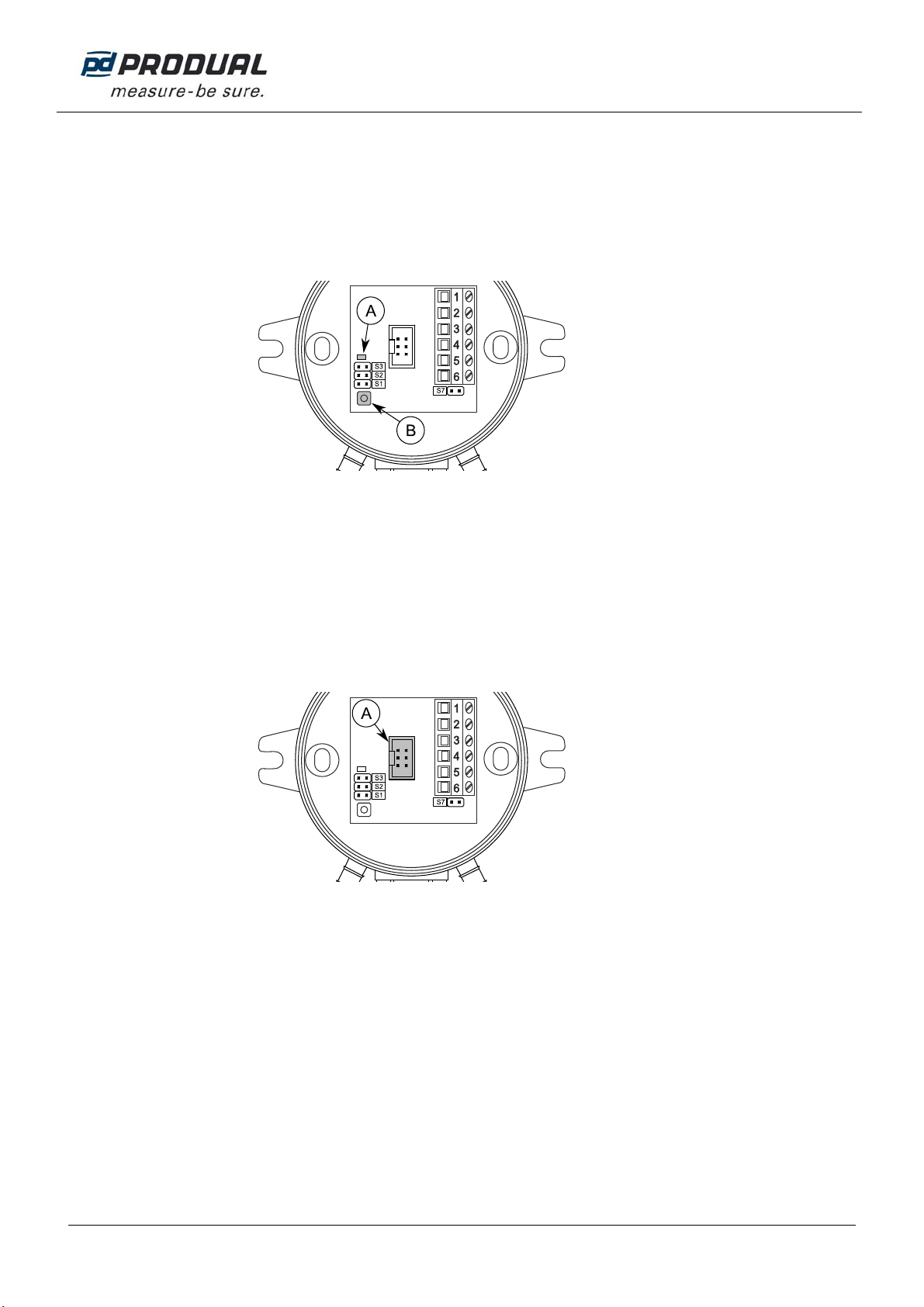
Indicator light functions
A. Indicator light
- The indicator light is illuminated for one second when the power is connected.
- The indicator light illuminates when the transmitter sends data to Modbus (M models only).
Selecting measuring range
Measuring range can be selected with the jumper S1.
A. Measuring range selection jumper
Pa 0…500 0…1000 *)
S1
*)Factory setting. The 0…1000 Pa range is also used for the custom range setting.
The custom range is 0…1000 Pa as a default. The range can be changed by using ML-SER tool or by defining the
high limit to the Modbus register 40006 (the low limit is 0 Pa).
USER GUIDE
PEL 1000 / PEL 1000-M
3 (8)
Produal Oy Keltakalliontie 18, 48770 Kotka FINLAND Tel: +358 10 219 9100 / Fax: +358 5 230 9210 [email protected]i www.produal.com
Information is subject to change without prior notice.
ZERO POINT CALIBRATION
The zero point drift can be eliminated by performing the zero point calibration. It is recommended to calibrate the zero
point every 6 months. At the commissioning the zero point calibration should be done after one hour of powering the
transmitter.
1. Unplug the plastic tubes from the inlets.
2. Press the zeroing button until the indicator light lights up (without flashing).
A. Indicator light
B. Zeroing button
ML-SER TOOL
With the ML-SER tool you can change the device settings, Modbus and controller settings for example.
Connecting ML-SER tool to the device
1. Remove the cover.
2. Disconnect the display cable (N models).
3. Connect the ML-SER tool cable to the display connector.
A. Display connector
When the ML-SER is successfully connected, the pressure measurement value is displayed on the ML-SER
tool display. The connecting can take few seconds.

USER GUIDE
PEL 1000 / PEL 1000-M
4 (8)
Produal Oy Keltakalliontie 18, 48770 Kotka FINLAND Tel: +358 10 219 9100 / Fax: +358 5 230 9210 [email protected]i www.produal.com
Information is subject to change without prior notice.
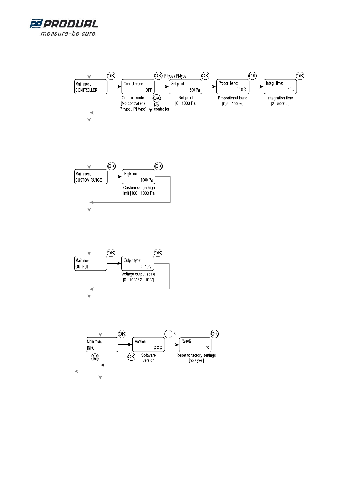
ML-SER menu
The device settings can be changed by using the ML-SER tool. You can proceed in the menu by pressing the M and
OK buttons. The values can be changed with the ”+” and ”-” buttons. The value is accepted with the OK button. The
following menu structure contains the factory settings.
The Modbus, controller function and analog output are disabled in the menu mode. In addition the analog output
maintains the same voltage, as it was before the menu mode.
*)Span calibration parameters are displayed for two seconds before returning to the main menu.

USER GUIDE
PEL 1000 / PEL 1000-M
5 (8)
Produal Oy Keltakalliontie 18, 48770 Kotka FINLAND Tel: +358 10 219 9100 / Fax: +358 5 230 9210 [email protected]i www.produal.com
Information is subject to change without prior notice.
Communications menu (M models only)
The Modbus settings can be changed through the COMMUNICATIONS menu.
Calibration menu
The CALIBRATION menu is for pressure measurement span calibration. To calibrate, you need to know the pressure
measurement deviation at a single pressure.
You need the following equipment for the calibration.
- ML-SER tool.
- A reference pressure meter.
- A stable pressure source (calibration pressure must be at least 275 Pa).
- Hoses for pressure connections.
Calibration
1. Connect the transmitter and the reference pressure meter to the same pressure source.
2. Connect the ML-SER to the transmitter.
3. Navigate to the calibration menu.
4. Read the pressure values from the ML-SER tool and the reference pressure meter.
5. Press + and – buttons on the ML-SER tool to adjust the transmitter pressure measurement to same value as
the reference.
The measurement can be tuned ±25 Pa.
+
–
Actual
Measured
Pa
Pa
For example if you adjust +5 Pa at 1000 Pa, the device will now read 1005 Pa at that pressure.
Correspondingly reading is corrected +10 Pa at 2000 Pa.
6. Press OK to save the span calibration.
The calibration parameter values are displayed for two seconds before returning to the menu.
USER GUIDE
PEL 1000 / PEL 1000-M
6 (8)
Produal Oy Keltakalliontie 18, 48770 Kotka FINLAND Tel: +358 10 219 9100 / Fax: +358 5 230 9210 [email protected]i www.produal.com
Information is subject to change without prior notice.
Controller menu
In the CONTROLLER menu the measurement output can be changed to controller output.
NOTE: The controller proportional band is 0.5…100 % from the selected pressure range.
Custom range menu
The CUSTOM RANGE menu is for setting the custom pressure range limits. The custom range is in use when all the
pressure range selection jumpers are placed.
Output menu
You can change the output scale through the OUTPUT menu.
Info menu
The INFO menu can be used for checking the software version and resetting to the factory settings.
Resetting to the factory settings
1. Press the “-“ button for five seconds in the software version display.
2. Change the resetting dialog answer to “yes”.
3. Press OK button.
The factory settings are now reset.
USER GUIDE
PEL 1000 / PEL 1000-M
7 (8)
Produal Oy Keltakalliontie 18, 48770 Kotka FINLAND Tel: +358 10 219 9100 / Fax: +358 5 230 9210 [email protected]i www.produal.com
Information is subject to change without prior notice.
MODBUS
Bus properties
Protocol RS-485 Modbus RTU
Bus speed 9600/19200/38400/57600 bit/s
Data bits 8
Parity none/odd/even
Stop bits 1
Network size up to 127 devices per segment
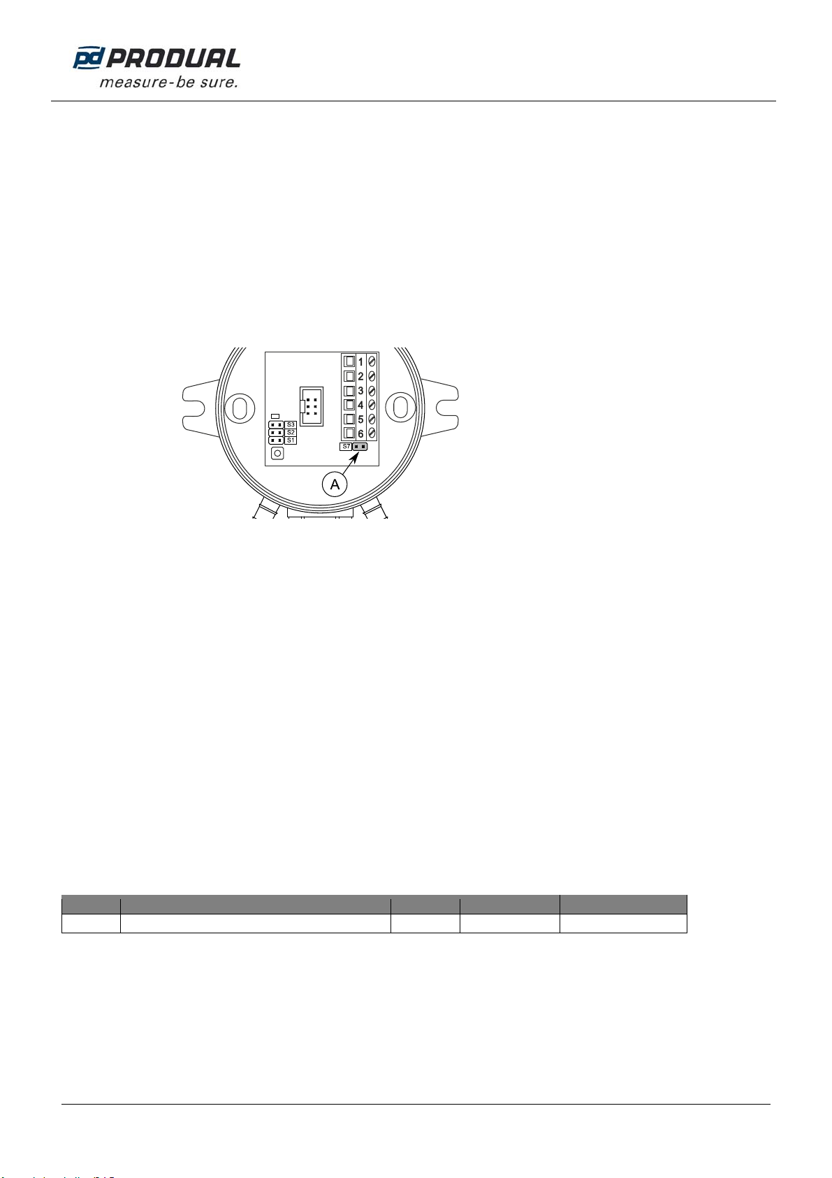
Bus termination
The Modbus can be terminated by placing the Modbus termination jumper (S7).
A. Modbus termination jumper
Supported Modbus functions
0x01 Read Coils
0x02 Read Discrete Inputs
0x03 Read Holding Registers
0x04 Read Input Registers
0x05 Write Single Coil
0x06 Write Single Register
0x0F Write Multiple Coils
0x10 Write Multiple Registers
0x17 Read/Write Multiple Registers
Modbus registers
Data types:
bit = 0 or 1
unsigned = unsigned integer (0…65535)
signed = integer (-32768…32767)
Discrete inputs (read only)
Register Parameter description Data type Value Range
10001Zeroing button is pressed within 1 minute bit 0…1 no=0, yes=1

USER GUIDE
PEL 1000 / PEL 1000-M
8 (8)
Produal Oy Keltakalliontie 18, 48770 Kotka FINLAND Tel: +358 10 219 9100 / Fax: +358 5 230 9210 [email protected]i www.produal.com
Information is subject to change without prior notice.
Input registers (read only)
Register Parameter description Data type Value Range
30001 Pressure measurement signed 0…1100 0…1100 Pa
30002 Selected pressure range unsigned 0 - 1 0 = 0…500 Pa
1 = 0…1000 Pa /
custom *)
30003 Zero value of the sensor signed -200…200 -200…200 Pa
30004 Analogue output voltage unsigned 0…1000 0…10.00 V
*) The custom range is 0…1000 Pa as a default. The range can be changed by using ML-SER tool or by defining the high limit to the
Modbus register 40006 (the low limit is 0 Pa).
Holding registers (read / write)
Register Parameter description Data type Value Range Default
40001 Control mode unsigned 0 - 1 - 2 0 = off
1 = P
2 = PI
0
40002 Set point unsigned 0…1000 0…1000 Pa
40003 Proportional band signed 5…1000 0.5…100 % 500
40004 Integration time signed 2…5000 2…5000 s 10
40005 Output mode unsigned 0 - 1 0 = 0…10 V
1 = 2…10 V 0
40006 Custom range high limit (low limit = 0 Pa) unsigned 1…10 100…1000 Pa 10
This manual suits for next models
1
Table of contents
Other Produal Transmitter manuals


Popular Transmitter manuals by other brands


Audiovox
Audiovox UltraGuard UG-OE3 Programming guide

RKI Instruments
RKI Instruments 65-2641RK-03 Operator's manual

HITROL
HITROL HT-100PT instruction manual

HK Instruments
HK Instruments DPT-2W- 100-R2 user guide

TE Connectivity
TE Connectivity AST4300 operating instructions

Decade
Decade MS-100 series instruction manual