Produal RT Series User manual

RT - Room transmitter
User Guide

Published: 22.01.2024 2 (26)
Contents
1 Introduction.............................................................................. 3
1.1 About this user guide.................................................................................................3
1.2 Intended use.............................................................................................................3
2 Safety precautions.................................................................... 4
3 Main components...................................................................... 5
4 Functional description...............................................................6
4.1 Multifunctional outputs............................................................................................... 6
4.2 Indicator lights.......................................................................................................... 6
5 Commissioning.......................................................................... 7
5.1 Mounting room transmitters........................................................................................ 7
5.2 Wiring.......................................................................................................................7
5.3 Configuring transmitter using MyProdual®.....................................................................8
5.3.1 Configuring measurement settings.................................................................. 10
5.3.2 Configuring output settings............................................................................ 16
5.3.3 Saving and uploading configurations................................................................17
5.4 Updating device firmware..........................................................................................18
6 Modbus....................................................................................19
6.1 Modbus properties....................................................................................................19
6.2 Modbus function codes............................................................................................. 19
6.3 Modbus registers......................................................................................................19
6.3.1 Input registers.............................................................................................. 19
6.3.2 Holding registers........................................................................................... 21
7 Disposal.................................................................................. 26
Produal Oy | Keltakalliontie 18, FI 48770 Kotka, Finland | tel. +358 10 219 9100 | [email protected]
Information is subject to change without prior notice.
EN - 53022W0000ug

Published: 22.01.2024 3 (26)
1 Introduction
RT transmitters are versatile room temperature and CO₂ transmitters for simple measuring
applications in building automation.
The transmitters can be equipped with following options:
• relative humidity measurement (-RH models)
• Modbus communication (-MOD models)
The -MOD models have Modbus RTU communication via the RS-485 connection.
Note: -MOD models don't include any other outputs.
The device commissioning is done by using MyProdual® smartphone application and MyTool® Connect
commissioning tool. Some of the basic settings can be also configured via bus in -MOD models.
1.1 About this user guide
This user guide contains important information about the installation, wiring, configuration and use of
the product. Read this guide carefully before you install the product, connect the wires, or operate the
product. Make sure that you fully understand all instructions before you start work. If you are not sure
what the instructions mean, contact the seller or the manufacturer.
Follow all instructions in this user guide carefully. Always obey the applicable local rules and
regulations.
The original instructions were written in English. If there are differences between the English
instructions and the translations, refer to the English instructions.
If you find a mistake in the English instructions or in the translations, please send the details to the
manufacturer.
1.2 Intended use
Versatile RT room transmitters are intended to be used for measuring temperature, humidity and CO₂
in room environment.
These transmitters are intended to be connected to building automation systems in the HVAC/R
industry.
Produal Oy | Keltakalliontie 18, FI 48770 Kotka, Finland | tel. +358 10 219 9100 | [email protected]
Information is subject to change without prior notice.
EN - 53022W0000ug
Published: 22.01.2024 4 (26)
2 Safety precautions
The product is developed, manufactured and tested according to high quality standards. However,
instructions for safe use shall be taken account when installing, using or disposing the product or parts
of product.
Read this user guide carefully before commissioning, using or servicing this device. To avoid any kind
of damage to people or property, follow the instructions carefully. Produal is not liable for any hazards
or damages to people or property which are caused by ignoring the using or installation instructions.
To avoid electrical shock or damage to equipment, disconnect power before installing or servicing the
product. Use only a proper wiring rated for the full operating voltage and maximum current in the
system even in the event of a fault.
To avoid potential fire and/or explosion, do not use the product in potentially flammable or explosive
atmosphere.
The product condition must be checked before installation. Do not drop the product or use excessive
force during installation. Do not use the product if any damages are visible.
After installation the product will be part of a system whose specifications and performance
characteristics are not designed or controlled by Produal. Refer to national and local authorities to
ensure that the installation is functional and safe.
The product should only be used in professionally designed applications. Unauthorised modifications
are not allowed. The product must not be used in relation with any equipment that in case of a failure
may threaten, directly or indirectly, human health or life or result in danger to human beings, animals
or property.
In this document, there are different kind of warnings and notes. The warning and note types are
defined in the following table.
Sign Description
WARNING: The warning symbol indicates a potentially hazardous situation which, if not
avoided, could result in death or serious injury.
CAUTION: The caution symbol indicates a potentially hazardous situation which, if not avoided,
could result in minor or moderate injury.
Important: The important symbol indicates a potentially hazardous situation which, if not
avoided, could result in damage to the device or property.
Note: The note symbol indicates a useful tip or a recommended way to complete a task.
These notes also provide information that is useful but not critical to the user.
Produal Oy | Keltakalliontie 18, FI 48770 Kotka, Finland | tel. +358 10 219 9100 | [email protected]
Information is subject to change without prior notice.
EN - 53022W0000ug
Published: 22.01.2024 5 (26)
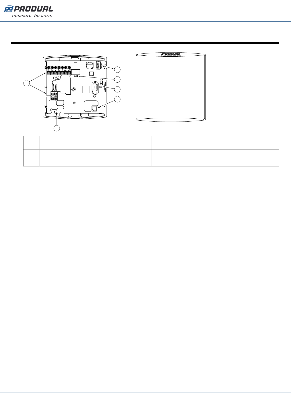
3 Main components
1
2
3
6
4
5
1 Terminal block 2 Temperature sensor / Temperature and humidity
sensor (-RH models)
3 CO2 sensor 4 Communication indicator light (-MOD models)
5 Modbus termination jumper (-MOD models) 6 MyTool® Connect connector
Produal Oy | Keltakalliontie 18, FI 48770 Kotka, Finland | tel. +358 10 219 9100 | [email protected]
Information is subject to change without prior notice.
EN - 53022W0000ug

Published: 22.01.2024 6 (26)
4 Functional description
4.1 Multifunctional outputs
The device has three configurable outputs. The outputs can be configured for the following purposes:
• analogue measurement output (freely scalable inside 0...10 Vdc)
• two-state output (e.g. 0/10 Vdc)
• control the output via communication bus
You can use the two-state output for a simple thermostat type control by setting the wanted
measurement value contact settings and selecting the measurement contact to control the output.
Configuration can be done via communication bus or by using MyTool® Connect and MyProdual®.
4.2 Indicator lights
The -MOD models have an indicator light on the circuit board. The indicator light can be set for
following functions:
• off
• data transmit indication
• data receiving indication
• data transmit and receiving indication
CAUTION: When the power supply is connected, be extra careful when handling the product
without the cover.
Produal Oy | Keltakalliontie 18, FI 48770 Kotka, Finland | tel. +358 10 219 9100 | [email protected]
Information is subject to change without prior notice.
EN - 53022W0000ug
Published: 22.01.2024 7 (26)
5 Commissioning
5.1 Mounting room transmitters
The device can be installed in dry surroundings (IP20) by screws on the wall surface or on the standard
flush mounting box. The recommended installation height is 150...180 cm.
The device position should be selected carefully. All the error factors that can affect to the
measurements should be eliminated as well as possible. The following list defines the typical
measurement error factors.
• direct sun light
• occupant proximity
• air flow coming from windows or doors
• air flow coming from ventilation nozzles
• air flow coming from the flush mounting box
• differential temperature caused by external wall
5.2 Wiring
WARNING: Device wiring and commissioning can only be carried out by qualified
professionals. Always make the device wirings in de-energised electricity network.
WARNING: External power sources and power wiring must be protected with a fuse or circuit
breaker. Rating depends on the overall system load, but the maximum rating for the external
circuit breaker is 16 A (limited by internal structure of the product).
WARNING: The minimum power rating for the external power source must be 170 VA / 170 W
to ensure proper operation of the internal fusing of the product in case of a failure condition.
Otherwise, the overall system power consumption shall be less than 15 W also in the failure
condition.
WARNING: This product is appliance class III product according to IEC 60664‑1. The product
may only be connected to SELV (separated extra low voltage) electricity network.
Important: This product has no capability to detect an abnormal condition of output ports.
External supervising (automated/human) may be needed depending on the application where
this product is used.
CAUTION: The product may only be connected to overvoltage category I, II or III electricity
network according to IEC 60664‑1.
Produal Oy | Keltakalliontie 18, FI 48770 Kotka, Finland | tel. +358 10 219 9100 | [email protected]
Information is subject to change without prior notice.
EN - 53022W0000ug
Published: 22.01.2024 8 (26)
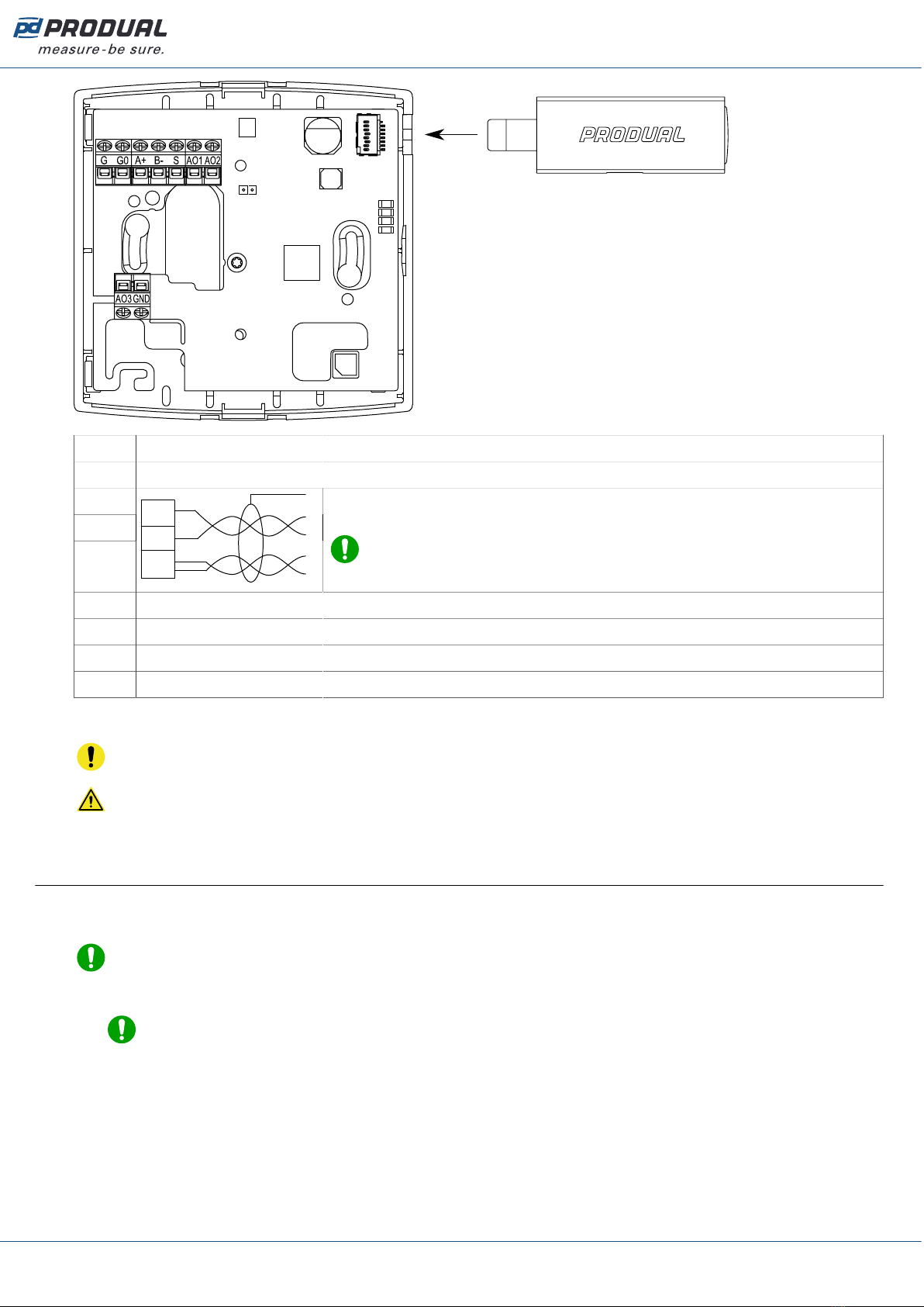
GSupply, 24 Vac/dc, < 1 VA
G0 0 V
A+
B-
SS
A+
B-
Modbus RTU, RS-485 (-MOD models).
Note: Connector S can only be used for chaining the cable shield
pair.
AO1 Voltage output 1, 0...10 Vdc, < 2 mA (freely scalable within this range). Not available in -MOD models.
AO2 Voltage output 2, 0...10 Vdc, < 2 mA (freely scalable within this range). Not available in -MOD models.
AO3 Voltage output 3, 0...10 Vdc, < 2 mA (freely scalable within this range). Not available in -MOD models.
GND Ground
The nominal wire terminal screw tightening torque is 0.4 Nm.
Important: Do not use excessive force when tightening the wiring terminal screws.
CAUTION: Ensure that all covers are closed before connecting supply voltage to the product.
Don't remove the covers when the supply voltage is connected.
5.3 Configuring transmitter using MyProdual®
To configure the device, you first need to connect it to MyProdual® application. When the device is
connected to application, you can make changes to the configuration.
Note: You need MyTool® Connect for connecting MyProdual® to the device.
1. Connect the supply voltage to the device.
Note: You can also power the device by connecting a USB cable to MyTool® Connect.
Produal Oy | Keltakalliontie 18, FI 48770 Kotka, Finland | tel. +358 10 219 9100 | [email protected]
Information is subject to change without prior notice.
EN - 53022W0000ug
Published: 22.01.2024 9 (26)
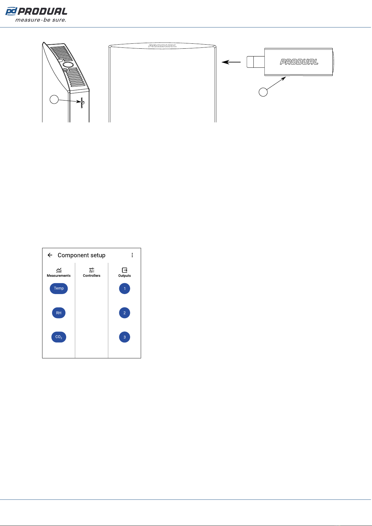
2. Insert the MyTool® Connect to the connector.
A
B
A. MyTool® Connect connector
B. MyTool® Connect
The indicator light in MyTool® Connect flashes when the Bluetooth is ready for connecting.
3. Start MyProdual®.
4. Tap the Quick access button.
5. Tap the Bluetooth connection button.
The device list shows the devices that have Bluetooth activated.
6. Tap the device to from the list to connect.
The indicator light in MyTool® Connect is illuminated continuously when MyProdual® is connected
to the device.
7. Tap the Configuration button.
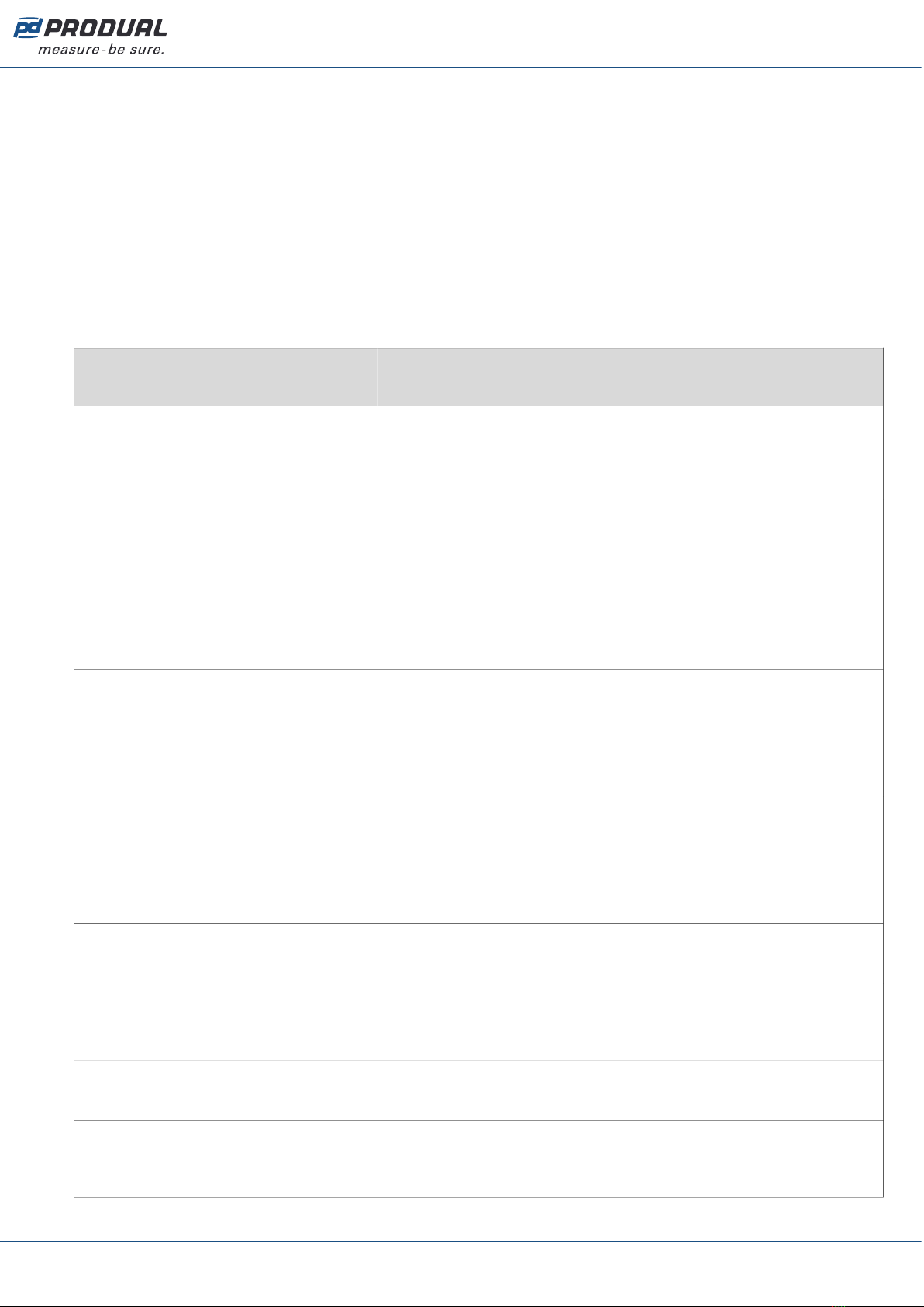
8. Tap the Component setup button.
Component setup view is divided in sections:
Measurements Set up measurements.
Outputs Set up outputs.
See more information about the settings from the following chapters.
9. Make the changes to configuration.
Produal Oy | Keltakalliontie 18, FI 48770 Kotka, Finland | tel. +358 10 219 9100 | [email protected]
Information is subject to change without prior notice.
EN - 53022W0000ug

Published: 22.01.2024 10 (26)
10. In -MOD models, press the General communication settings button to configure communication
settings
The following parameters are available for configuration:
Parameter
name
Values Default Description
Communication
mode
Off / Modbus RTU Modbus RTU Communication mode.
RS485 baud rate 9600 / 14400 /
19200 / 38400 /
56000 / 57600 /
76800 / 115200
9600 Bus speed.
Parity None / Even / Odd None Bus parity.
Stop bits 1 bit / 2 bits 1 bit Stop bits.
Communication led
mode
Off / Tx / Rx / Tx
+ Rx
Tx + Rx Communication indicator light function.
Off Indicator light is off
Tx Indicator light is on when the
device transmits data to bus.
Rx Indicator light is on when the
device receives data from bus.
Tx + Rx Indicator light is on when the
device transmits data to bus or
receives data from bus.
When this option is selected,
the transmit hold on time is ten
times the hold on time setting.
Communication led
hold on time
5…1000 ms 25 ms Communication indicator light hold on time.
Modbus slave ID 1...247 1 Modbus address.
Modbus broadcast Disabled / Enabled Enabled Modbus broadcast.
11. Tap Install to device button to write the changes to the device.
Note: The changes can also saved to device in each configuration view tapping the Save
button.
12. Tap the button.
13. Tap the connection info button to disconnect the device.
14. Remove the MyTool® Connect.
5.3.1 Configuring measurement settings
All device models include temperature and CO2 measurements. Other measurements available for
configuration depend on the model.
1. Tap the Component setup button on the Configuration page to open the Component setup page.
Produal Oy | Keltakalliontie 18, FI 48770 Kotka, Finland | tel. +358 10 219 9100 | [email protected]
Information is subject to change without prior notice.
EN - 53022W0000ug
Published: 22.01.2024 11 (26)
2. Tap a button in the Measurements column for the measurement you want to configure.
The Measurements column can have the following measurement settings available depending on
the device model:
Temp Set up temperature measurement settings.
RH Set up relative humidity measurement settings. Available for -RH models.
CO₂ Set up CO2 measurement settings.
5.3.1.1 Temperature measurement settings
Tap the Temp button on the Component setup page to open the temperature measurement settings.
Tap a parameter on the list to change its value.
The following parameters are available for configuration:
Parameter
name
Values Default Description
Measurement scale
min
-100.0...100.0 °C 0.0 °C Temperature measurement at 0 %. Set the
value for temperature measurement when the
transmitter output is 0 %. For example, if this
value is 0 °C, then 0 % voltage is interpreted as
0 °C.
Measurement scale
max
-100.0...100.0 °C 100.0 °C Temperature measurement at 100 %. Set the
value for temperature measurement when the
transmitter output is 100 %. For example,
if this value is 50 °C, then 100 % voltage is
interpreted as 50 °C.
Time constant
multiplier
60...3600 s 120 s This value defines how quickly the transmitter
responds to a rapid change in temperature. The
measurement reaches 63 % of its final value by
this time. Advanced settings.
Contact on level -100.0...100.0 °C 25.0 °C This temperature is interpreted as contact
ON value. This function works as a “software
contact", and it can be linked to the digital
output. If the measured temperature is higher
than the value set for this parameter, then the
output signal is at the maximum value set for
the output.
Contact off level -100.0...100.0 °C 24.0 °C This temperature is interpreted as contact
OFF value. This function works as a “software
contact", and it can be linked to the digital
output. If the measured temperature is lower
than the value set for this parameter, then the
output signal is at the minimum value set for
the output.
Contact turn on
delay
0…65535 s 0 s The delay in seconds before the contact is
turned on after the Contact on level condition is
fulfilled. Advanced settings.
Contact hold on
time
0…65535 s 0 s Contact hold on time (seconds). This time
defines how long the contact stays on even
if the Contact off level condition is fulfilled.
Advanced settings.
Contact turn off
delay
0…65535 s 0 s The delay in seconds before the contact is
turned off after the Contact off level condition is
fulfilled. Advanced settings.
Contact hold off
time
0…65535 s 0 s Contact hold off time (seconds). This time
defines how long the contact stays off even
if the Contact on level condition is fulfilled.
Advanced settings.
Produal Oy | Keltakalliontie 18, FI 48770 Kotka, Finland | tel. +358 10 219 9100 | [email protected]
Information is subject to change without prior notice.
EN - 53022W0000ug
Published: 22.01.2024 12 (26)
Parameter
name
Values Default Description
Measurement
correction Off
Offset
Span
Off You can use the measurement correction to
adjust the temperature measurement values,
if necessary. If you select Offset, you can set
the temperature offset in degrees. The same
offset is used at all temperatures. If you select
Span, you can define two temperatures and
a measurement correction value for each.
Advanced settings.
Temperature offset -100.0...100.0 °C 0.0 °C Temperature offset in degrees. Set the offset
that will be used at all temperatures to correct
the measurement values. Shown if Offset
is selected in the Measurement correction
parameter.
Point 1
measurement
-100.0...100.0 °C 0.0 °C Temperature for point 1 measurement
correction. Set the temperature at which the
measurement correction is applied to the
measurement. For example, if you want to
correct the measurement by 0.5 °C at 0 °C,
set this parameter value to 0.0 °C. Shown if
Span is selected in the Measurement correction
parameter.
Point 1 correction -100.0...100.0 °C 0.0 °C The amount of measurement correction for
point 1. Set the measurement correction in
degrees. For example, if you want to correct
the measurement by 0.5 °C at 0 °C, set this
parameter value to 0.5 °C. Shown if Span
is selected in the Measurement correction
parameter.
Point 2
measurement
-100.0...100.0 °C 0.0 °C Temperature for point 2 measurement
correction. Set the temperature at which the
measurement correction is applied to the
measurement. For example, if you want to
correct the measurement by -1 °C at 25 °C,
set this parameter value to 25.0 °C. Shown if
Span is selected in the Measurement correction
parameter.
Point 2 correction -100.0...100.0 °C 0.0 °C The amount of measurement correction for
point 2. Set the measurement correction in
degrees. For example, if you want to correct
the measurement by -1 °C at 25 °C, set this
parameter value to -1.0 °C. Shown if Span
is selected in the Measurement correction
parameter.
5.3.1.2 Relative humidity measurement settings
Relative humidity measurement settings are available in -RH models. Tap the RH button on the
Component setup page to open the relative humidity measurement settings. Tap a parameter on the
list to change its value.
The following parameters are available for configuration:
Parameter
name
Values Default Description
Measurement scale
min
0.00...100.00 rH% 0.00 rH% Relative humidity measurement at 0 %. Set
the value for humidity measurement when
the transmitter output is 0 %. For example,
if this value is 0.00 rH%, then 0 % voltage is
interpreted as 0 %rH.
Produal Oy | Keltakalliontie 18, FI 48770 Kotka, Finland | tel. +358 10 219 9100 | [email protected]
Information is subject to change without prior notice.
EN - 53022W0000ug

Published: 22.01.2024 13 (26)
Parameter
name
Values Default Description
Measurement scale
max
0.00...100.00 rH% 100.00 rH% Relative humidity measurement at 100 %. Set
the value for humidity measurement when the
transmitter output is 100 %. For example, if
this value is 80.00 rH%, then 100 % voltage is
interpreted as 80 %rH.
Time constant
multiplier
60...3600 120 This value defines how quickly the transmitter
responds to a rapid change in relative humidity.
The measurement reaches 63 % of its final
value by this time. Advanced settings.
Contact on level 0.00...100.00 rH% 50.00 rH% This humidity value is interpreted as contact
ON value. This function works as a “software
contact", and it can be linked to the digital
output. If measured humidity is higher than the
value set for this parameter, then the output
signal is at the maximum value set for the
output.
Contact off level 0.00...100.00 rH% 49.00 rH% This humidity value is interpreted as contact
OFF value. This function works as a “software
contact", and it can be linked to the digital
output. If measured humidity is lower than the
value set for this parameter, then the output
signal is at the minimum value set for the
output.
Contact turn on
delay
0…65535 s 0 s The delay in seconds before the contact is
turned on after the Contact on level condition is
fulfilled. Advanced settings.
Contact hold on
time
0…65535 s 0 s Contact hold on time (seconds). This time
defines how long the contact stays on even
if the Contact off level condition is fulfilled.
Advanced settings.
Contact turn off
delay
0…65535 s 0 s The delay in seconds before the contact is
turned off after the Contact off level condition is
fulfilled. Advanced settings.
Contact hold off
time
0…65535 s 0 s Contact hold off time (seconds). This time
defines how long the contact stays off even
if the Contact on level condition is fulfilled.
Advanced settings.
Measurement
correction Off
Offset
Span
Off You can use the measurement correction to
adjust the humidity measurement values,
if necessary. If you select Offset, you can
set the humidity offset in rH%. If you select
Span, you can define two humidity points and
a measurement correction value for each.
Advanced settings.
Humidity offset -100...100 rH% 0 rH% Relative humidity offset. Set the offset that will
be used at all humidity levels to correct the
measurement values. Shown if Offset is selected
in Measurement correction.
Point 1
measurement
0...100 rH% 0 rH% Relative humidity for point 1 measurement
correction. Set the humidity value at which
the measurement correction is applied to the
measurement. For example, if you want to
correct the measurement by 2 rH% at 15 rH%,
set this parameter value to 15 rH%. Shown if
Span is selected in Measurement correction.
Produal Oy | Keltakalliontie 18, FI 48770 Kotka, Finland | tel. +358 10 219 9100 | [email protected]
Information is subject to change without prior notice.
EN - 53022W0000ug

Published: 22.01.2024 14 (26)
Parameter
name
Values Default Description
Point 1 correction 0...100 rH% 0 rH% The amount of measurement correction for
point 1. Set the measurement correction in
rH%. For example, if you want to correct the
measurement by 2 rH% at 15 rH%, set this
parameter value to 2 rH%. Shown if Span is
selected in Measurement correction.
Point 2
measurement
0...100 rH% 0 rH% Relative humidity for point 2 measurement
correction. Set the humidity value at which
the measurement correction is applied to the
measurement. For example, if you want to
correct the measurement by 3 rH% at 80 rH%,
set this parameter value to 80 rH%. Shown if
Span is selected in Measurement correction.
Point 2 correction 0...100 rH% 0 rH% The amount of measurement correction for
point 2. Set the measurement correction in
rH%. For example, if you want to correct the
measurement by 3 rH% at 80 rH%, set this
parameter value to 3 rH%. Shown if Span is
selected in Measurement correction.
5.3.1.3 CO2 measurement settings
CO2 measurement settings are available in -CO2 models. Tap the CO₂ button on the Component setup
page to open the CO2 measurement settings. Tap a parameter on the list to change its value.
The following parameters are available for configuration:
Parameter
name
Values Default Description
Measurement scale
min
0...10000 ppm 0 ppm CO2 measurement at 0 %. Set the value for CO2
measurement when the transmitter output is 0
%. For example, if this value is 0 ppm, then 0 %
voltage is interpreted as 0 ppm.
Measurement scale
max
0...10000 ppm 2000 ppm CO2 measurement at 100 %. Set the value for
CO2 measurement when the transmitter output
is 100 %. For example, if this value is 2000
ppm, then 100 % voltage is interpreted as 2000
ppm.
Time constant
multiplier
60...3600 120 This value defines how quickly the transmitter
responds to a rapid change in CO2 level. The
measurement reaches 63 % of its final value by
this time. Advanced settings.
Contact on level 0...10000 ppm 1200 ppm This CO2 value is interpreted as contact ON
value. This function works as a “software
contact", and it can be linked to the digital
output. If the measured CO2 level is higher
than the value set for this parameter, then the
output signal is at the maximum value set for
the output.
Contact off level 0...10000 ppm 1100 ppm This CO2 value is interpreted as contact OFF
value. This function works as a “software
contact", and it can be linked to the digital
output. If the measured CO2 level is lower
than the value set for this parameter, then the
output signal is at the minimum value set for
the output.
Contact turn on
delay
0…65535 s 0 s The delay in seconds before the contact is
turned on after the Contact on level condition is
fulfilled. Advanced settings.
Produal Oy | Keltakalliontie 18, FI 48770 Kotka, Finland | tel. +358 10 219 9100 | [email protected]
Information is subject to change without prior notice.
EN - 53022W0000ug

Published: 22.01.2024 15 (26)
Parameter
name
Values Default Description
Contact hold on
time
0…65535 s 0 s Contact hold on time (seconds). This time
defines how long the contact stays on even
if the Contact off level condition is fulfilled.
Advanced settings.
Contact turn off
delay
0…65535 s 0 s The delay in seconds before the contact is
turned off after the Contact off level condition is
fulfilled. Advanced settings.
Contact hold off
time
0…65535 s 0 s Contact hold off time (seconds). This time
defines how long the contact stays off even
if the Contact on level condition is fulfilled.
Advanced settings.
Measurement
correction Off
Offset
Span
Off You can use the measurement correction
to adjust the CO2 measurement values, if
necessary. If you select Offset, you can set the
CO2 offset in ppm. The same offset is used at all
CO2 levels. If you select Span, you can define
two CO2 levels and a measurement correction
value for each. Advanced settings.
CO₂ offset -10000...10000
ppm
0 ppm CO2 offset in ppm. Set the offset that will
be used at all CO2 levels to correct the
measurement values. Shown if Offset is selected
in Measurement correction.
Point 1
measurement
0...10000 ppm 0 ppm CO2 level for point 1 measurement correction.
Set the CO2 level at which the measurement
correction is applied to the measurement.
For example, if you want to correct the
measurement by 10 ppm at 420 ppm, set this
parameter value to 420 ppm. Shown if Span is
selected in Measurement correction.
Point 1 correction 0...10000 ppm 0 ppm The amount of measurement correction for
point 1. Set the measurement correction in
ppm. For example, if you want to correct the
measurement by 10 ppm at 420 ppm, set this
parameter value to 10 ppm. Shown if Span is
selected in Measurement correction.
Point 2
measurement
0...10000 ppm 0 ppm CO2 level for point 2 measurement correction.
Set the CO2 level at which the measurement
correction is applied to the measurement.
For example, if you want to correct the
measurement by 20 ppm at 900 ppm, set this
parameter value to 20 ppm. Shown if Span is
selected in Measurement correction.
Point 2 correction 0...10000 ppm 0 ppm The amount of measurement correction for
point 2. Set the measurement correction in
ppm. For example, if you want to correct the
measurement by 20 ppm at 900 ppm, set this
parameter value to 20 ppm. Shown if Span is
selected in Measurement correction.
CO₂ ABC calibration Disabled
Enabled
Enabled Automatic self-calibration of CO2 measurement.
If this function is enabled, it eliminates the
possible long-term drift in CO2 measurement
accuracy.
CO₂ ambient
pressure correction Disabled
Enabled
Disabled Ambient pressure correction for CO2
measurement. If this function is enabled, you
can use the local ambient pressure for CO2
measurement. If this function is disabled, the
transmitter uses the ambient pressure at sea
level.
Produal Oy | Keltakalliontie 18, FI 48770 Kotka, Finland | tel. +358 10 219 9100 | [email protected]
Information is subject to change without prior notice.
EN - 53022W0000ug

Published: 22.01.2024 16 (26)
Parameter
name
Values Default Description
CO₂ ambient
pressure correction
value
700...1200 hPa 1013 hPa Set this value to the local ambient pressure.
Shown if the CO₂ ambient pressure correction
parameter value is Enabled.
5.3.2 Configuring output settings
1. Tap the Component setup button on the Configuration page to open the Component setup page.
2. Tap a button in the Outputs column for the output you want to configure.
The Outputs column can have the following measurement settings available depending on the
device model:
1Output 1 settings.
2Output 2 settings.
3Output 3 settings.
3. Tap the Output type button.
4. Select the output type and tap Ok.
The following output types are available:
Off Not in use.
Analog Analogue output.
Digital Digital output.
5. Make the settings for the output.
See more information about the settings from the following chapters.
5.3.2.1 Analogue output settings
Tap the output number button on the Component setup page to open the output settings. Select
Analog for output type. Tap a parameter on the list to change its value.
The following parameters are available for configuration:
Parameter
name
Values Default Description
Analog output
source T measurement
RH measurement
CO₂ measurement
Bus
T measurement Analogue output source.
0-10 V
2-10 V
0-5 V
Custom
0-10 V Analogue output signal range.
0.000...10.000 V - Custom analogue output voltage range.
0.00...100.00 % - Custom analogue output effective range.
5.3.2.2 Digital output settings
Tap the output number button on the Component setup page to open the output settings. Select Digital
for output type. Tap a parameter on the list to change its value.
The following parameters are available for configuration:
Produal Oy | Keltakalliontie 18, FI 48770 Kotka, Finland | tel. +358 10 219 9100 | [email protected]
Information is subject to change without prior notice.
EN - 53022W0000ug

Published: 22.01.2024 17 (26)
Parameter
name
Values Default Description
Digital output
selection Temperature
contact
RH contact
CO₂ contact
Bus
Temperature
contact
Digital output control source.
0-10 V
2-10 V
0-5 V
Custom
0-10 V Digital output signal range.
0.000...10.000 V - Custom digital output voltage range.
0.00...100.00 % - Custom digital output effective range.
5.3.3 Saving and uploading configurations
If you have several devices to configure, you can save the configuration and then upload it to other
devices. Configurations are model-specific.
You can save configurations to MyCloud® or locally to your smartphone.
5.3.3.1 Saving the configuration to MyCloud®
1. After you have configured the settings, tap the three dots in the upper right corner of the
Configuration page.
2. Tap Save to MyCloud to save the new configuration to MyCloud®.
3. Enter a name for the configuration in the Configuration name field.
4. If necessary, enter an optional description in the Description field.
5. Tap Next to select the saving location.
6. Select Personal workspace or Shared workspace, if your company has a shared workspace.
7. Tap Save to save the configuration.
5.3.3.2 Uploading a saved configuration to a transmitter from MyCloud®
1. Connect the transmitter to MyProdual® application.
See section Configuring transmitter using MyProdual® on page 8 for the connection
instructions.
2. Tap the cloud icon on top of the Configuration page.
3. Tap a saved configuration on the Open configurations page to select it.
4. Tap the Open button in the top right corner.
5. Select the settings you want to import in the Import settings popup.
6. Tap the Open button to open the configuration settings.
7. Tap the Install to device button at the bottom of the Configuration page to upload the settings to
the device.
5.3.3.3 Saving the configuration locally
You can save configurations locally to your smartphone.
1. After you have configured the settings, tap the three dots in the upper right corner of the
Configuration page.
2. Tap Save configuration locally to save the configuration to the smartphone MyProdual® is installed
in.
Produal Oy | Keltakalliontie 18, FI 48770 Kotka, Finland | tel. +358 10 219 9100 | [email protected]
Information is subject to change without prior notice.
EN - 53022W0000ug
Published: 22.01.2024 18 (26)
3. Enter a name for the configuration in the Configuration name field.
4. If necessary, enter an optional description in the Description field.
5. Tap Next to select the saving location.
6. Navigate to the correct folder.
a. In Android, tap the Save button to save the configuration file.
b. In iOS, tap Open to save the configuration file.
5.3.3.4 Uploading a locally saved configuration to a transmitter
1. Connect the transmitter to MyProdual® application.
See section Configuring transmitter using MyProdual® on page 8 for the connection
instructions.
2. Tap the three dots in the upper right corner of the Configuration page.
3. Tap Open local file in the menu.
4. Tap a saved configuration to select it.
5. Select the settings you want to import in the Import settings popup.
6. Tap the Open button to open the configuration settings.
7. Tap the Install to device button at the bottom of the Configuration page to upload the settings to
the device.
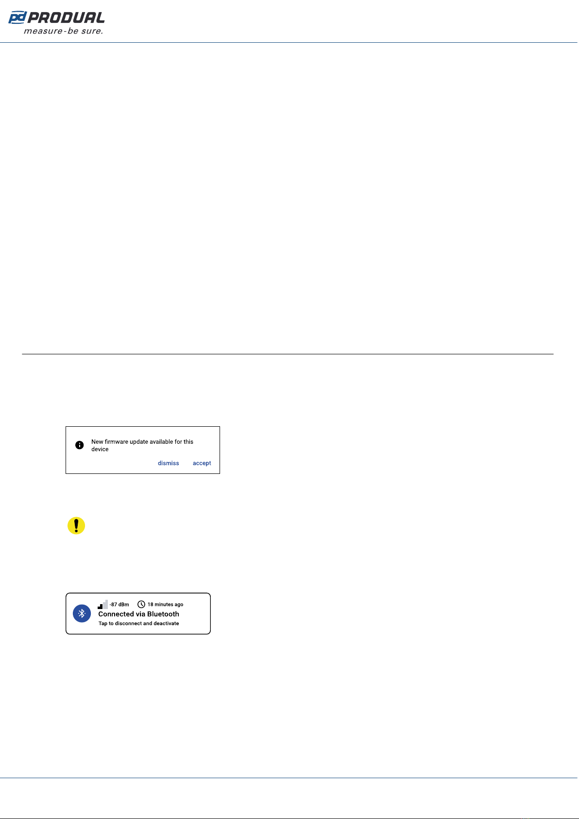
5.4 Updating device firmware
You can update the device firmware when the MyProdual® notifies about the update.
1. Start MyProdual®.
2. Connect the device to MyProdual®.
3. Tap the accept button on the update notification.
4. Review the update details and tap the Install button to start the update.
5. Wait for the firmware installation process to complete.
Important: Keep the mobile phone near the device to keep Bluetooth active. If the
connection is lost, the firmware update process can not complete.
6. Tap the Ok button in the firmware update completion dialog.
7. Tap the Close button.
8. Tap the connection info button to disconnect the device.
Produal Oy | Keltakalliontie 18, FI 48770 Kotka, Finland | tel. +358 10 219 9100 | [email protected]
Information is subject to change without prior notice.
EN - 53022W0000ug

Published: 22.01.2024 19 (26)
6 Modbus
The -MOD models are equipped with Modbus RTU communication via RS‑485 connection.
6.1 Modbus properties
Protocol RS-485 Modbus RTU
Bus speed 9600*/14400/19200/38400/56000/57600/76800/115200 bit/s
Data bits 8
Parity none*/odd/even
Stop bits 1* / 2
Modbus ID 1*
Unit load 1/8 UL
* factory setting
6.2 Modbus function codes
The device supports the following Modbus function codes.
Decimal Hexa-
decimal
Function
3 0x03 Read Holding Registers
4 0x04 Read Input Registers
6 0x06 Write Single Register
16 0x10 Write Multiple Registers
23 0x17 Read/Write Multiple Registers
6.3 Modbus registers
The device uses the whole Modbus register space from 1 to 65535. Holding registers and input
registers are not tied to classic 4xxxx and 3xxxx areas. There are also many registers that has the
same register number but the function depends on the register type.
Important: Some BMS systems may need extra configuring to able to use the whole register
space. Contact the system vendor support if needed.
The registers are grouped according to the user guide. You can read or write only registers from one
group with the same Modbus command.
6.3.1 Input registers
6.3.1.1 Input registers for measurements
Input
register
Parameter description Data
type
Values Range
0Temperature measurement (°C). S16 -10000...10000 -1000.0...1000.0 °C
1Relative humidity measurement. U16 0...100 0...100 %
2CO2 measurement. U16 0...10000 0...10000 ppm
3...12 Not in use. U16 - -
Produal Oy | Keltakalliontie 18, FI 48770 Kotka, Finland | tel. +358 10 219 9100 | [email protected]
Information is subject to change without prior notice.
EN - 53022W0000ug

Published: 22.01.2024 20 (26)
Input
register
Parameter description Data
type
Values Range
13 Voltage output 1. U16 0...10000 0.000...10.000 V
14 Voltage output 2. U16 0...10000 0.000...10.000 V
15 Voltage output 3. U16 0...10000 0.000...10.000 V
16 Not in use. U16 - -
17 Average temperature (°C). S16 -10000...10000 -1000.0...1000.0 °C
18 Dew point (°C). S16 -10000...10000 -1000.0...1000.0 °C
19 Relative humidity with one decimal. U16 0...1000 0.0...100.0 %
20 Relative humidity with two decimals. U16 0...10000 0.0...100.0 %
21 Absolute humidity. U16 0...1000 0.0...100.0 g/m3
22 Mixing ratio of water vapour. U16 0...1000 0.0...100.0 (g/kg)
23 Enthalpy. U16 0...10000 0.0...1000.0 kJ/kg
24...31 Not in use. U16 - -
32 Temperature measurement (°F). S16 -17680…18320 -1768.0…1832.0 °F
33 Not in use. U16 - -
34 Average temperature (°F). S16 -17680…18320 -1768.0…1832.0 °F
35 Dew point (°F). S16 -17680…18320 -1768.0…1832.0 °F
6.3.1.2 Input registers for contacts
Input
register
Parameter description Data
type
Values Range
52 Measured temperature contact. U16 0 - 1 0. Off
1. On
53 Measured humidity contact. U16 0 - 1 0. Off
1. On
54 Measured CO2 contact. U16 0 - 1 0. Off
1. On
55...57 Not in use. U16 - -
58 Output 1 contact. U16 0 - 1 0. Off
1. On
59 Output 2 contact. U16 0 - 1 0. Off
1. On
60 Output 3 contact. U16 0 - 1 0. Off
1. On
6.3.1.3 Input registers for device status
Input
register
Parameter description Data
type
Values Range
63 Device status. U16 0 - 1 0. Ok
1. Fault
64 Temperature sensor status. U16 0 - 1 0. Ok
1. Fault
Produal Oy | Keltakalliontie 18, FI 48770 Kotka, Finland | tel. +358 10 219 9100 | [email protected]
Information is subject to change without prior notice.
EN - 53022W0000ug
Table of contents
Other Produal Transmitter manuals


