manuals.online logo
Brands
  1. Home
  2. •
  3. Brands
  4. •
  5. PROEL
  6. •
  7. Security System
  8. •
  9. PROEL AE300 Specification sheet

PROEL AE300 Specification sheet

AE300
INTEGRATED VOICE ALARM SYSTEM • EN54-16 EN54-4
OPERATING AND INSTALLATION MANUAL
AE300R1
VOICE ALARM
FAULT WARNING
DISABLEMENTS
SYSTEM FAULT
POWER
SYSTEM STATUS
EVACUATE
ALARM
ACTIVATION
BACKSILENCE
OK
AE300
INTEGRATED VOICE ALARM SYSTEM • EN54-16 EN54-4
3
1. INTRODUCTION
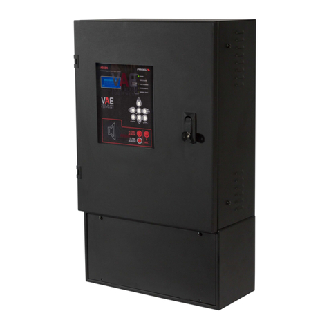
The AE300 voice alarm system is a device for signalling in case of fire, designed according to EN Standards 54-16 and
54-4 It is an integrated, monolithic system with a single casing containing the voice alarm system blocks and the
power supply unit with backup batteries The system can play back recorded alarm messages through the monitored
contact inputs, or an operator can speak directly through a microphone integrated in the front panel, or from a
remote emergency microphone workstation
The system also has inputs for a service microphone workstation, background music diffusion, contacts for playing
back generic messages, as well as an Ethernet port
Depending on the model, the system has (or does not have) a backup amplifier
2. SAFETY NOTES AND ARNINGS
This manual must be viewed before the equipment is put into service.
•This device must be installed in accordance with UNI Standard EN54-32:2015 and serviced only by qualified
personnel.
•This manual must be read and understood before commissioning the device.
•This device is set-up for operation using mains voltage within the 230 V +10% -15% range and 48Vdc backup
batteries with 7.2A/h capacity.
•It is necessary to strictly follow the instructions in Par. 4.p “Connection to the mains power supply and
earthing”
•The device is protected by fuses on the main power supply (230V) and on the backup power supply (48Vdc
batteries). The fuses, respectively indicated as F1 and F2, are present on the power supply board.
F1=T3.15AH, F2=T8AH
•All connections must be made with device off.
•The end of a stranded conductor must not be terminated with a soft solder in the points in which the
conductor is subjected to a contact pressure (e.g. the header of the wirings which goes to the cable seal
terminals must not be tin-plated but terminated with a crimping ferrule.)
•It is the installer's obligation to prepare a 2 poles thermal-magnetic circuit breaker 6A-C6 (in appropriate
electrical panel) dedicated to this device. The circuit breaker must be placed in an easily accessible position.
The circuit breaker must bear the words “VOICE ALARM SYSTEM – DO NOT S ITCH-OFF”
•In order to avoid the risk of electric shocks, when accessing the inside of the device you must disconnect
the power supply network (230V). It is also necessary to disconnect the battery as there is a DANGEROUS
ENERGY LEVEL inside the machine (In reference to fastons J7 and J8).
•Do not expose the device to humidity or rain or any other liquid. Keep the device away from objects or
containers with liquid that could be accidentally poured inside, through the ventilation slots.
•Install the device in a cool, ventilated properly place and away from heat sources.
•Install the device so as not to obstruct the ventilation slots.
•Connect only batteries with the rated voltage and capacity described in this manual.
•Do not reverse the polarity of the batteries. + Positive / - Negative
•The batteries must have a casing with safety class. RIF. UL94:HB / UL94:V0.
•hen installing the device, be very careful not to damage the electronic card with tools (pliers,
screwdrivers, etc...).
4
3. MAIN FEATURES, FUNCTIONS ITH REQUIREMENT AND ACCESSORY FUNCTIONS.
•Integrated, single-zone (1 zone max) voice alarm system, with class D power amplifiers and power supply unit with primary source
(230Vac network) and backup source (48Vdc batteries)
•ARM Cortex M3 processor, DSP 16bit 48Khz
•Controlled dynamic microphone on front panel; microphone capsule continuity monitoring, cable cut and short-circuit
•Key or password to access the machine functional levels
•Alarm and generic messages, recorded on uSD card Contents monitored by system processor
•Class D power amplifiers, power 300W
•2 Speaker lines (line A and line B) with 100V constant voltage with transformer coupling
•Independent monitoring of the speaker lines (A+B) with direct measurement of AC voltage and current at 18Khz and FFT analysis
•2 Contact inputs with line monitored for alarm message activation (interruption and cable cut)
•8 contact inputs (not monitored) to activate generic and service messages
•3 Normally Open output contacts “Relay” for reporting the machine status: VOICE ALARM / FAULT WARNING / SYSTEM DISABLEMENT
•Input for remote emergency microphone workstation with monitored connection
•Input for generic microphone workstation for service messages
•RS485 port (reserved for future use)
•Ethernet port for remote communication (reporting of status, configuration, audio streams)
•Power supply unit according to Standard EN54-4 with main source (230Vac); backup source (48Vdc battery); temperature, battery
impedance and battery charger status monitoring
•Comprehensive user interface for a straightforward configuration
The following figure schematically shows the connections outside the system
VA 301
Postazione
di chiamata
Postazione
di Emergenza
Sorgente Sonora
LINEA A
Contatto Allarme
Contatto Evacuazione
LINEA B
CENTRALE
ANTI INCENDIO
SUBWOOFER
Attivo
Contatti Fault/Alarm/Disablement
RS 485
Ethernet
8x Contatti per messaggi generici
Call
workstation
Emergency
workstation
FIRE
-
FIGHTING
STATION
Alarm Contact
Evacuation Contact
Fault/Alarm/Disablement Contacts
8 Contacts for generic messages
Sound Source
LINE A
LINE B
External
Amplifier
AE300
5
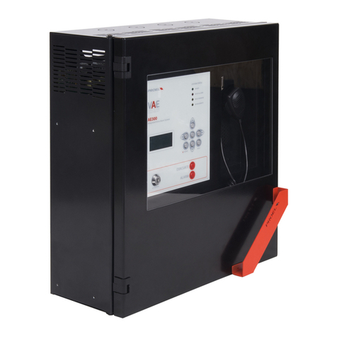
Front panel
The front panel of the machine has the user interface through which you can manage the system and view its status
At the top, the LEDs synthetically report the machine statuses:
•Green LED | PO ER: indicates that the machine is on and operating
•Red LED | VOICE ALARM: indicates that a voice alarm is being played back, the system is in VOICE ALARM status
•Yellow LED | FAULT ARNING: indicates the presence of one or more faults, the system is in FAULT ARNING status
•Yellow LED | DISABLEMENTS: indicates that one or more system sections has been deactivated, the system is in
DISABLEMENTS status
•Yellow LED | SYSTEM FAULT: indicates the program execution has been interrupted.
To restore the normal operation, unpower then repower the system:
Disconnect both mains and batteries, then repower by connecting back the mains and the
batteries
In the central part, the display shows the details on the machine status and, through the keyboard, you can access the internal menus
Bottom-right of the user panel, the ALARM and WARNING buttons manually activate alarm or evacuation messages To activate these alarm
messages, or access the machine functions in the menus, you must login at access level 2 with the key (bottom-left) or by entering a password in
the appropriate menu OK -> UP -> ACCESS LEVEL LOGIN -> OK -> Insert Password to access level 2 -> OK
Finally, there is a PTT microphone on the machine front panel for issuing speakerphone alarm and evacuation messages To activate the
microphone, you must login at access level 2 (with key or password), then press the key on the side of the microphone to speak
6
4.
INSTALLATION AND MAINTENANCE
The system must be installed by qualified personnel and in accordance with UNI Standard EN54-30
Unpack the device, loosen the two screws on the right of the front panel and rotate the door on the pins on the left side
Inside are the machine electronics composed of three or four cards, depending on the model (with or without backup amplifier)
4.a all mounting
Install the wall-mounting brackets according to the template enclosed in the package Make sure they are firmly installed Make sure that the
screws and plugs can handle the weight of the whole system and batteries
Finally, hang the unit on the mounting brackets Reference to pag 45, intructions for correct mounting
Use suitable type wall plugs according to the characteristics of the wall and with load from 0 30 to 0 65kN
The device must be fixed to the wall by qualified personnel
4.b Connection of the speaker lines
The terminals for connection to the speaker lines are located top-right on the main board, just below the fairlead window Connect the
loudspeaker lines to 100V as shown in the figure The overall load applied to the two lines must not exceed 300W
When wiring the loudspeaker lines, be very careful not to short-circuit the two poles between them. If the loudspeaker lines are in short-
circuit, the system is not able to play back any alarm message, even if the fault is reported on the user interface.
J10 – Line A output
1 – 100V +
2 – 100V -
Output at 100V constant voltage for loudspeaker line A
Power levels: 100Vac nom, 300Wrms nom, Rmin=33,3Ohm
Use twisted cable with min section 2 5mm / max 4mm
J11 – Line B output 1 – 100V +
2 – 100V -
Output at 100V constant voltage for loudspeaker line B
Power levels: 100Vac nom, 300Wrms nom, Rmin=33,3Ohm
Use twisted cable with min section 2 5mm / max 4mm
Note: in A+B configuration the sum of the powers applied to the 2 lines cannot exceed 300
4.c Audio output 0 dB
The system has a line level unbalanced line output for an active speaker or external amplifier
Connect the active speaker or external amplifier input to the mainboard terminal shown in the figure
7
J9 – Audio output 0 dB 1 – Line Out
2 - GND
0 db Line Output to External Amplifier
Power levels: 1 0Vrms, Ro=100ohm
Use shielded cable with min section 0 5 mm
4.d Status outputs
The unit has three relay outputs to report the state of the system
J8 – Relay outputs 1-2 – ALARM
3-4 – FAULT
5-6 – DISABLEMENT
Each relay can handle up to 500mA
ALARM e DISABLEMENT: N.O. Contact
FAULT: N.O. Contact. Please note that in the absence of power the
contact of FAULT switches to the closed position
4.e Generic messages activation contacts
The system has 8 unsupervised inputs for activating the generic and service messages recorded on uSD memory card Each message is activated
by closing its ground input, as shown in the figure below
The playback of the message is activated by a pulse Releasing the contact after shorting it to ground has no effect, but the message will be
played till its end When a message is being played, a second pulse will stop the player
Generic messages have predefined priorities: message n has a priority over message n+1.
Example:
•When message 2 is played, the closing of contact 1 will stop message 2 and start message 1
•When message 2 is played, the closing of contact 2 will stop message 2
•When message 2 is played, the closing of contact 3 is ignored
This said, message 8 will has the lowest priority, but message 1 has the highest
Each contact is active only if an associated audio file is stored in the uSD card, refer to relative menù section OK -> 3 x DOWN -> RECORDED
MESSAGES & SD
8
J7 – Unmonitored
contact inputs terminal
from 1 to 8 for service
messages activation
(not alarm messages)
1 – Message 8
2 – Message 7
3 – Message 6
4 – Message 5
5 – Message 4
6 – Message 3
7 – Message 2
8 – Message 2
9 – GND
Each input is active for closure to ground (Common GND)
Input Contacts are Normally Open (NO)
Input contacts are protected up to +42V compared to GND, an higher voltage can
seriously damage the relative electronic board
Use cable with min section 0 5 mm, max 2 5 mm
4.f Alarm messages activation monitored contacts
The system has two monitored dry contact inputs to trigger the EVACUATE and ALARM (alert) messages that are stored in the uSD
card The connection foresees two 2 2KOhm resistors, connection example described in the figure below (Alarm Input // Evacuate
Input)
As a factory default, both inputs will trigger their respective message at the opening of the contact (NC) and the playback will
continue cyclically as long as the input is open Playback will stop at the closing of the contact
These inputs, that are typically activated by the fire alarm control panel are monitored against short circuit and cable cut: in this
case, the system will trigger a fault warning
J6 – Alarm messages
activation monitored
contact inputs
Balance the lines with
2 2KOhm resistors
EVACUATION
1 – CONT 1 P
2 – CONT1 N
ALARM
3 – CONT 2 P
4 – CONT2 N
Connect the resistors (supplied in the accessory bag) on each pair of contacts as shown in
the figure The resistors must be placed at the end of the cable, from the smoke and fire
signalling station side
Refer to the CONF ALARM INPUT MODE menu for the properties and configuration of the
input contacts
The inputs of the alarm messages are, by default, configured for normally closed contacts
Use cable with min section 0 5 mm, max 2 5 mm
9
If you do not intend to use the remote activation of messages, you cannot leave these terminals open without the device reporting a fault
Therefore, connect two resistors 2 2Kohm directly on the mainboard terminal J6 (1-2 and 3-4) so that the device does not signal a connection
fault or a Voice Alarm
4.g Generic announcement microphone workstation
The system has an input for a microphone workstation for generic announcements, that is not evacuation and voice alarm announcements The
terminal shown in the figure has a balanced microphone input and a priority contact input
The microphone input for generic announcements also has +48V phantom power supply that can be activated from the menu ACCESS AT LEVEL
3 -> OK -> 7 x DOWN -> OK -> 6 x DOWN -> OK -> OK -> LEFT -> DOWN -> OK
J5 – Mic paging input 1 – MIC +
2 – MIC GND
3 – MIC -
4 – Priority
5 – GND Priority
Input for microphone paging workstation for generic announcements 48V Phantom
power supply that can be activated from menu: common mode on pin 1 and 3 compared
to pin 2
Power levels: 1 0Vrms max, Ri=600Ohm
Active contact for closure to ground, protected up to +42V compared to GND
Use cable with 0 5 mm min and 2 5 mm max section on priority contact
Use shielded cable with 0 5 mm min section on audio input
Note: For this application You can use the following microphone workstations: Code PA BM101 // PA BM102
10
4.h Music/line input
The system has a line input for connection to an audio source for background music diffusion
You can connect both sources with balanced output and sources with unbalanced output The following figures describe the connections
For the connection of audio sources with unbalanced output, connect the positive to terminal 1, the source ground to terminal three and leave
the central terminal free
J4 – Line input for audio
sources
1 – Audio P
2 – Common/Ground
3 – Audio N
Balanced line input, transformer insulated Used for background music diffusion
Power levels: 0 8Vrms @ 0dB, Ri=100Kohm
Use shielded cable for audio signal with min section 0 5mm
11
4.i Emergency microphone workstation
The system has a RJ45 input for connection to remote emergency microphone workstations (VAE series DBE01 // DBEVF) and monitored
according to Standard EN54-16
Connect the microphone workstation to socket rJ45 through a UTP CAT5 cable The connection between the two RJ45 pins to the cable end
must be 1-to-1
J3 – External emergency
mic workstation port
1 – Audio P
2 – Audio Gnd
3 – Audio N
4 – GND
5 – +24Vdc
6 – GND
7 – COMM P
C – COMM N
RJ45 Connector for connection to external emergency microphone workstation (DBExx
series) This connector carries both the audio signals and data link from and to the
external microphone workstation Connection is monitored and the system reports a fault
in case the communication with the microphone workstation is lost due to short-circuit or
cable cutting
Proprietary connection for connection to the dedicated microphone workstations only
Use 8-pole UTP CAT5 cable, 4 pairs Head the RJ45 connectors 1-to-1
4.l RS485 Serial connection
The system implements an RS485 communication port for connection to remote devices with dialogue through protocol, described in the
specific manual The following figure describes the connection between the AE300 and an external device, through RS485 port The jumper to
terminate the line is located behind the terminal With the jumper inserted, the line is terminated With the jumper not inserted, the line is not
terminated
J2 – RS485 1 – RS485 A
2 – RS485 B
3 - Ground
Port RS485 not insulated
Standard power levels ANSI TIA/EIA-485
Use shielded cable with min section 0 5 mm
12
4.m Ethernet port
The ethernet port allows connecting the system to a company data network, or a dedicated data network, to remotely monitor the machine and
connect several machines in a hierarchical manner
Ethernet port Standard pinout Ethernet port 10/100 Base T insulated with coupling to connector built-in transformers
Use UTP CAT5 cable
4.n uSD memory card
The housing for the uSD memory card (4Gb minimum) containing the recorded messages is located on the left side of the mainboard Before
extracting or inserting the card, activate the appropriate DISABLEMENT function of the uSD from the menu
The port-card connector is of a push-push type: to extract the card, push the uSD fully into the connector until you hear a “click”, then release
and extract the card
Insert the card with the contacts facing down and push until you hear a “click ”
4.o Installing and connecting batteries
The system provides the use of 4 batteries 12V 7 2A/h or 6 batteries 8V 6A/h connected in series to achieve rated 48V Install the batteries in the
bottom space, on the bottom of the container left of the toroidal transformer
13
The following figure shows the battery connection to the electronic card of the power supply unit
The power supply unit card is located bottom-right, between the two toroidal transformers
The faston terminals + and - 48V are on the bottom of the card
Connect the four batteries in SERIES (+ on -) with the faston-faston jumpers in the accessory bag
Connect the negative terminal of the battery pack to faston – on the power supply unit board
Connect the positive terminal of the battery pack to faston + 48V on the power supply unit board
Connecting the batteries the machine remains in stand-by and does not turn on
A two-pole white connector identified with “BATT TEMP PROBE” is located to the right of the fuse-holder Engage the temperature probe in the
connector and apply it to one of the batteries using adhesive tape
In the down-left PSU board corner there is a Service Button (see the following picture) that allows the machine to start-up when
the Main power 230V is not connected
During normal use (230Vac network connected and batteries connected) with the sudden interruption of the primary power supply, the
machine automatically switches to battery mode, if however you want to test the system on site, without having the 230Vac mains voltage
available, by simply connecting the batteries, the machine will not turn on automatically and the ignition must be forced, using the battery start
service button
ATTENTION: Don’t push that button if the Main power 230V is present
Note: If the PSU is in Disablement mode the Service Button is not Active, it is not possible to start-up the machine by batteries.
Note: In case of use of additional batteries positioned outside the EVAC control unit, and the consequent connection with long cables, we
recommend protecting the cables in a special pipe. Insert protection with circuit breaker or fuse or switch of suitable / A / h value.
14
4.p Connection to the mains power supply (N: Neutra – L: Line) and earthing
The terminal for the 230V mains power supply and earthing connection is located top-right, near the breakaway slot for cable inlet The Figure
here below shows the LINE, EARTH and NEUTRAL connections
For the connection to the power mains, provide a 6A-C6 circuit breaker dedicated to the equipment; this must be placed in an easily accessible
position
Use cables with a section of 2 5mm2 for both the mains power supply and earthing
Make sure that the signal cables, and the low voltage cables in general, do not accidentally touch the mains voltage points These are the
terminals for connection to the mains voltage, and the areas marked with the symbol inside the device
ATTENTION: example of 230Vac cable connection 3 poles + Neutral + Line + Earth
4.q Powering the system
After making and checking all connections, activate the circuit breaker
The system display indicates “POWER ON” and so begins the switch-on sequence
4.r Monitor loudspeaker volume
The trimmer for adjusting the monitor loudspeaker volume on the front panel of the device is located on the bottom of the mainboard
(indicated by the arrow in the figure) Enable the playback of any message (see specific menu), then rotate the trimmer to obtain the desired
volume
15
4.s Clock battery replacement
The battery-holder for the buffer battery of the internal clock and calendar is located on the bottom of the mainboard Although these batteries
have a very long life, we recommend replacing them every 24 months
To avoid having to reset date and time, you can replace the battery with the system on and powered
4.t Ordinary device maintenance
a) Periodically clean the device with a dry cloth
b) Periodically check that the ventilation openings are not obstructed
c) Periodically check the wiring and connections
d) Periodically check the efficiency of the earthing connection
e) Replace the Pb-Gel batteries every 4 years with units having the same voltage and capacity
f) Replace the CR2032 battery of the internal clock (see par 4s) every 4 years
g) Check the status of EVAC and ALARM messages
16
5. MENU DESCRIPTION
5.1 Status Description
The system is designed to manage different operating conditions which, according to Standard EN54, are identified in four statuses The system
status is displayed by the LEDs on the front panel of the system and of the remote emergency microphone workstations
QUIET Status:
Operating condition “at rest”, without faults, no playback of voice alarms and no active “disablements ” Only the
diffusion of background music or generic messages (not alarm ones) is allowed When the system is in the quiet
status only the green LED is lit on the front panel of the unit, to indicate that the system is powered
ALARM Status (VOICE ALARM):
Operating condition where a pre-recorded or speakerphone voice alarm is being issued from the emergency
microphone workstation It can be activated via an external device connected to one of the supervised contacts, or
from an emergency microphone workstation While a voice alarm is issued, the system turns on the red LED to
indicate the voice alarm status The green LED remains on to indicate that the system is powered
The display will show a POP-UP window indicating the source of the voice alarm in progress
FAULT Status (FAULT ARNING):
Operating condition indicating the presence of at least one fault detected by the internal diagnostic system The
status indication is accompanied by a fault intermittent acoustic signal (buzzer) and the yellow LED lighting up on
the unit panel The green LED remains on to indicate that the system is powered
The display will show a POP-UP window indicating the number of detected faults and a brief description
DISABLEMENTS Status:
Operating condition in which the functions of one or more system sections are disabled
Even the faults related to the disabled section are suspended since safety functions are deactivated This condition
allows operating on the system without turning it off and without the fault condition (FAULT WARNIGS) being
activated
The display will show a POP-UP window indicating the number of active “disablements” and a brief description of
the section(s)
SYSTEM FAULT Status
The system status led indicated that the system software has crashed, or that the unit has eventually self-initialized
The visual and acoustic indication will remain undefinitely
To reset the indication, the unit must be fully unpowered (disconnect both mains and batteries), and then
repowered according to the procedure described in this manual
NOTE: Operating conditions may also occur simultaneously The LEDs corresponding to the active conditions will light up on the front panel and
the display will show a POP-UP window indicating which and how many events are active If the number of events exceeds the number of rows
of the POP-UP window, indications will cyclically scroll on the display In this case you can view entries using the UP and DOWN arrows
If 3 differents kind of events occur together (Voice Alarms – Faults Warning – Disablements), the POP-UP window will show them separated
on 3 groups ( Voice Alarms group – Faults Warnings group – Disablements group)
For consulting the events inside each group must be used UP and Down buttons for moving over the desired group and push Right button
17
5.2 Main Screen
In the absence of warnings, the main screen shows the following information:
•System time: shows the current system time; for the system events to be properly recorded, this should
be always updated It is also important to verify that seconds are regularly counted, otherwise the system
CPU may be locked
•Current access level: A key indicates the current access level 1, 2 or 3
•System status: The “System OK” text indicates that the system is operating
In case of a fault, a POP-UP window will appear indicating the number of active faults, the presence and
number of “disablements” and if an alarm message is in progress
Icons
Current access level: a key positioned bottom-left of the display indicates the current access level: 1, 2 or 3
Message playback with active repeat rules In case alarm or evacuation messages are played back, an icon with
two alternate arrows may appear to indicate the presence of rules in the number of repetitions of the current
message The rules impose a minimum number of reproductions and/or a maximum number of reproduction
cycles
Fault of one of the two lines A or B with volume increase In case of line fault with redundant A&B line, an icon
will appear to indicate that the “non-faulty” line is working with an indicated volume increase
Mute on With mute on, an icon with the loudspeaker crossed is displayed to indicate that the mute is active
During the playback of a pre-recorded or voice message you can activate the “MUTE” function by pressing the
appropriate button on the front panel; when on, an icon with a crossed loudspeaker appears on the display
To deactivate, simply press the appropriate button again and mute will be removed
NOTE: as per EN54-16, when “Mute” is activated during the playback of a pre-recorded message, the output is
muted only at the end of the message itself to avoid compromising its intelligibility Likewise, when mute is
removed, the message will be played back at the end of the reproduction cycle Mute activation while an
emergency microphone is “speaking” is immediately effective
Warning on In case of a system event, a flashing triangle appears to attract the user’s attention The warning is
removed when you access the “System Logs” system event menu, which lists the system events
18
5.3 Menu Description And Navigation
Using the keyboard on the front panel
From the home screen where the display shows the general status, press OK
to access the menu
structure.
The OK key in the sub-menus is used to confirm the selection of the element pointed by the navigation
arrow.
Use the U and DOWN keys to scroll the list of menus and sub-menus.
ress OK to access the menu or sub-menu pointed by the navigation arrow.
ress BACK to go back to the previous menu or cancel the selection of a function. Repeatedly pressing
the BACK key from any workstation returns to the main screen.
Alternatively, you can access the selected menu or sub-menu by pressing the RIGHT key, and go back to
the previous menu or sub-menu by pressing the LEFT key.
The main menu is structured in the form of a list in which the functional parts of the system are managed:
Menu tree
•Line & Amplifiers Management of Diffuser lines and amplifiers
•Power supply & Battery Management of primary power supply (220V) and secondary (Battery)
•Fire microphone Management of the emergency microphone workstations
•Recorded messages & SD Management of pre-recorded messages on micro-SD card
•Input contacts Management of contacts to launch messages
•Alarm Buttons Management of Alarm – Evacuation frontal buttons
•Ethernet Management of ethernet connection
•System status & Conf System configuration
•Volumes Volumes configuration
•Message Scheduler Configuration of hourly programming of pre-recorded messages
•System Logs Display of system events
•Access level login User authentication
19
LINE & AMPLIFIERS Menu
The Line & Amplifiers menu allows you to view and manage the status of amplifiers
and speaker lines They appear in the form of a list and can be scrolled using the UP
and DOWN arrows Each amplifier and speaker line is linked to the summary status:
Status of the amplifiers:
DISABLED  Disabled (Disablement)
ABSENT  Not installed
FAULT  Faulty
ARNING  Pre-alarm condition
OK  Running
Status of the lines:
DISABLED  Disabled (Disablement)
NOT IN USE  Not in use
NO CALIB  Impedance not calibrated
FAULT  Faulty
OK  Running
The system works with a Main amplifier and a possible Back p amplifier Both the
main amplifier and the backup amplifier, if installed, are monitored to ensure
effectiveness; in case of a faulty main amplifier, the backup amplifier automatically
takes over, if installed
For details of the status of the amplifiers you can select from the list and press OK to
access the Main amplifier detail / Back p amplifier detail screen that indicates the
status in detail In particular, the display shows the type of amplifier selected and its
operating status:
Func: Connected / Active  Connected to the load and active
Connected / Powerdown  Connected to the load and in energy saving
mode
Disconneted / Powerdown Disconnected from the load and in energy
saving mode
The system works with a single line of speakers that can be managed in single or
double mode, also called A&B mode The content diffused via speakers is unique in
both single-line and double-line mode, A&B line The difference between the two
modes is the possibility, in A&B mode, to manage a fault on the speaker line and
recover the lost sound pressure by transferring power on the line that is still operating
In the event of a fault, e g short-circuit, of the single-mode speaker line (not A&B), the
system isolates the line to avoid damaging the amplifier, making it impossible to
diffuse any contents On the contrary, if the line of speakers was wired in double
mode, alternating a line A speaker with a line B speaker and homogeneously
distributing the speakers on the surface to be sonorised; in the event of a fault on one
of the two lines, e g short-circuit, the system isolates the faulty line and increase the
volume of the remaining line so as to recover the lost sound pressure
For details of the status of the lines, you can select from the list and press OK to access
the Line A detail / Line B detail screen that indicates the status in detail In particular,
the display shows the status, operation and possible error for the selected line of
speakers
The following errors can be managed:
Detail: GND SHORT  Earthed speaker line
NO LOAD DETECTED  Speaker line interrupted
20
UNDERLOAD  Loss of line load
OVERLOAD  Increase of line load
BAD LOAD  Line impedance not manageable
LOAD SHORT  Line in short-circuit
The speaker line can be connected or disconnected:
Func: Connected  Speaker line connected
Disconnected Speaker line disconnected
To access the POP-UP where to insert or remove the “disablement” condition, you
must have access level 2, otherwise a screen is displayed where you are required to
login to carry out this operation
From the POP-UP, with the section in “disablement” you can calibrate the line
impedance by selecting the “Calibrate line” command; execution is immediate and the
outcome is shown on the status detail screens of the line of speakers This operation
measures the line impedance at 20KHz to continuously evaluate any changes denoting
a change in load
NOTE: When the “Line & Amp” section is in “disablement,” all safety functions related
to the amplifiers and speaker lines are deactivated Any “FAULTS” are also removed
The “disablement” function allows working on the speaker lines without interrupting
the system operation and without generating “FAULTS ”
When the line calibration command is selected, the screen changes and a counter
appears indicating the time to wait for the procedure to be performed, at the end of
which a screen summarising the outcome appears
Listed below is the status of the two amplifiers and of the two lines managed by the
system
•Main Amp:  Primary amplifier
•Backup Amp:  Backup amplifier
Status of the amplifiers:
ABSENT  Not installed
FAULT  Faulty
OVERTEMP  Condition of overheating
OK  Running
•Line A:  Speaker line A
•Line B:  Speaker line B
Speaker line status:
DISABLED  Not in use
GND SHORT  Earthed speaker line
NO LOAD DETECTED  Speaker line interrupted
UNDERLOAD  Loss of line load
OVERLOAD  Increase of line load
BAD LOAD  Line impedance not manageable
LOAD SHORT  Line in short-circuit

Other manuals for AE300

2

This manual suits for next models

1

Other PROEL Security System manuals

PROEL PROEVAC EVO EV PROM5Z Operating manual

PROEL

PROEL PROEVAC EVO EV PROM5Z Operating manual

PROEL AE604 Specification sheet

PROEL

PROEL AE604 Specification sheet

PROEL AE300 Specification sheet

PROEL

PROEL AE300 Specification sheet

PROEL PRO EVAC SYSTEM User guide

PROEL

PROEL PRO EVAC SYSTEM User guide

PROEL AE300 Specification sheet

PROEL

PROEL AE300 Specification sheet

Popular Security System manuals by other brands

GE AS272 installation manual

GE

GE AS272 installation manual

Electro Detectors Zerio Plus EDA-T6080 installation manual

Electro Detectors

Electro Detectors Zerio Plus EDA-T6080 installation manual

Nokia 6 Product guide

Nokia

Nokia 6 Product guide

E2S BExCBL2-L2D-P instruction manual

E2S

E2S BExCBL2-L2D-P instruction manual

Teradek ace 800 quick start guide

Teradek

Teradek ace 800 quick start guide

E2S D1 B2X05 Series instruction manual

E2S

E2S D1 B2X05 Series instruction manual

ring VIDEO DOORBELL manual

ring

ring VIDEO DOORBELL manual

Holmes Z1100 Quick reference guide

Holmes

Holmes Z1100 Quick reference guide

Telco Sensors Space Guard Series user manual

Telco Sensors

Telco Sensors Space Guard Series user manual

Valco Cincinnati LLD manual

Valco Cincinnati

Valco Cincinnati LLD manual

Lorex LW2002B Series Specifications

Lorex

Lorex LW2002B Series Specifications

My ADT ITI Concord Express Getting to know

My ADT

My ADT ITI Concord Express Getting to know

ADEMCO 745x3 installation instructions

ADEMCO

ADEMCO 745x3 installation instructions

Honeywell LYNX Touch L5210 Series Installation and startup guide

Honeywell

Honeywell LYNX Touch L5210 Series Installation and startup guide

Maretron ALM100-01 user manual

Maretron

Maretron ALM100-01 user manual

Uniden UDW10055 user manual

Uniden

Uniden UDW10055 user manual

Lorex LWB3800 Series Quick connection guide

Lorex

Lorex LWB3800 Series Quick connection guide

Texecom ComGSM installation manual

Texecom

Texecom ComGSM installation manual

manuals.online logo
manuals.online logoBrands
  • About & Mission
  • Contact us
  • Privacy Policy
  • Terms and Conditions

Copyright 2025 Manuals.Online. All Rights Reserved.