manuals.online logo
Brands
  1. Home
  2. •
  3. Brands
  4. •
  5. PROEL
  6. •
  7. Security System
  8. •
  9. PROEL AE604 Specification sheet

PROEL AE604 Specification sheet

Other PROEL Security System manuals

PROEL AE300 Specification sheet

PROEL

PROEL AE300 Specification sheet

PROEL AE300 Specification sheet

PROEL

PROEL AE300 Specification sheet

PROEL PRO EVAC SYSTEM User guide

PROEL

PROEL PRO EVAC SYSTEM User guide

PROEL PROEVAC EVO EV PROM5Z Operating manual

PROEL

PROEL PROEVAC EVO EV PROM5Z Operating manual

PROEL AE300 Specification sheet

PROEL

PROEL AE300 Specification sheet

Popular Security System manuals by other brands

Polon-Alfa 4000 Installation and maintenance manual

Polon-Alfa

Polon-Alfa 4000 Installation and maintenance manual

Nexcom NViS 14162 Series user manual

Nexcom

Nexcom NViS 14162 Series user manual

Eminent EM8670 Quick install

Eminent

Eminent EM8670 Quick install

urmet domus alpha 1060 INSTALLATION AND USE BOOKLET

urmet domus

urmet domus alpha 1060 INSTALLATION AND USE BOOKLET

SmartPool YardGuard YG03 manual

SmartPool

SmartPool YardGuard YG03 manual

DSC PC5964 Mounting instructions

DSC

DSC PC5964 Mounting instructions

Secure USAB-1 operating instructions

Secure

Secure USAB-1 operating instructions

B&B 480 SERIES Operation & maintenance manual

B&B

B&B 480 SERIES Operation & maintenance manual

ADEMCO VISTA-20P Series Installation and setup guide

ADEMCO

ADEMCO VISTA-20P Series Installation and setup guide

Inner Range Concept 2000 user manual

Inner Range

Inner Range Concept 2000 user manual

Johnson Controls PENN Connected PC10 Install and Commissioning Guide

Johnson Controls

Johnson Controls PENN Connected PC10 Install and Commissioning Guide

Aeotec Siren Gen5 quick start guide

Aeotec

Aeotec Siren Gen5 quick start guide

Swann SW-P-MC2 Specifications

Swann

Swann SW-P-MC2 Specifications

Ecolink Siren+Chime user manual

Ecolink

Ecolink Siren+Chime user manual

EDM Solution 6+6 Wireless-AE installation manual

EDM

EDM Solution 6+6 Wireless-AE installation manual

Siren LED GSM operating manual

Siren

Siren LED GSM operating manual

Detection Systems 7090i Installation and programming manual

Detection Systems

Detection Systems 7090i Installation and programming manual

FRIEDLAND MA10 Installation and operating instructions

FRIEDLAND

FRIEDLAND MA10 Installation and operating instructions

manuals.online logo
manuals.online logoBrands
  • About & Mission
  • Contact us
  • Privacy Policy
  • Terms and Conditions

Copyright 2025 Manuals.Online. All Rights Reserved.

AE604
INTEGRATED VOICE ALARM SYSTEM • EN54-16 EN54-4
OPERATING AND INSTALLATION MANUAL
AE604
VOICE ALARM
FAULT WARNING
RETURN
PRE
ALARM
DISABLEMENTS
SYSTEM FAULT
POWER
SYSTEM
STATUS
SILENCE
OK
4 Zones Integrated Voice Alarm System
AE604
EVAC
ALARM
MIC
AE604
INTEGRATED VOICE ALARM SYSTEM • EN54-16 EN54-4
3
1. INTRODUCTION
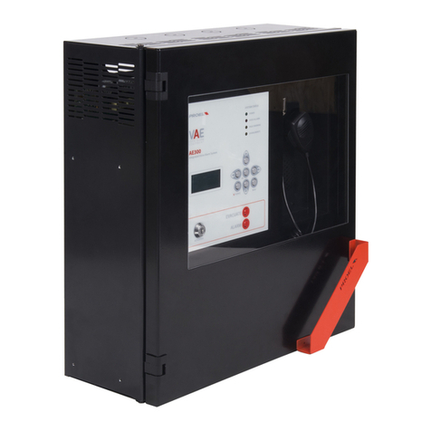
The AE604 voice alarm system is a 4 zones unit or signalling in case o ire, designed according to EN Standards 54-16
and 54-4. It is an integrated monolithic system containing the voice alarm system blocks and the power supply unit
with backup batteries in a dedicated case attached to the main body o the unit. The system can play recorded alarm
messages through the monitored contact inputs, or an operator can speak directly through a microphone integrated
in the ront panel, or rom a remote emergency microphone callstation.
The system also has inputs or a service microphone station, background music di usion, contacts or playing back
generic messages, as well as an Ethernet port.
2. SAFETY NOTES AND WARNINGS
T is manual must be viewed before t e equipment is put into service.
•T is device must be installed in accordance wit UNI Standard EN54-32:2015 and serviced only by qualified
personnel.
•T is manual must be read and understood before commissioning t e device.
•T is device is set-up for operation using mains voltage wit in t e 230 V +10% -15% range and 48Vdc backup
batteries wit 18A/ capacity.
•It is necessary to strictly follow t e instructions in Par. 4.p “Connection to t e mains power supply and
eart ing”
•T e device is protected by fuses on t e main power supply (230V). T e fuse F3 is present on t e power
supply module F3=T4AH.
•All connections must be made wit t e device unpowered.
•T e end of a stranded conductor must not be terminated wit a soft solder in t e points in w ic t e
conductor is subjected to a contact pressure (e.g. t e eader of t e wirings w ic go to t e cable seal
terminals must not be tin-plated but terminated wit a crimping ferrule).
•It is t e installer's obligation to prepare a 2 poles t ermal-magnetic circuit breaker 6A-C6 (in appropriate
electrical panel) dedicated to t is device. T e circuit breaker must be placed in an easily accessible position.
T e circuit breaker must bear t e words “VOICE ALARM SYSTEM – DO NOT SWITCH-OFF”.
•In order to avoid t e risk of electric s ocks, w en accessing t e inside of t e device you must disconnect
t e power supply network (230V). It is also necessary to disconnect t e battery as t ere is a DANGEROUS
ENERGY LEVEL inside t e mac ine.
•Do not expose t e device to umidity or rain or any ot er liquid. Keep t e device away from objects or
containers wit liquid t at could be accidentally poured inside, t roug t e ventilation slots.
•Install t e device in a cool, ventilated properly place and away from eat sources.
•Install t e device so as not to obstruct t e ventilation slots.
•Connect only batteries wit t e rated voltage and capacity described in t is manual.
•Do not reverse t e polarity of t e batteries. + Positive / - Negative.
•T e batteries must ave a casing wit safety class. RIF. UL94:HB / UL94:V0.
•W en installing t e device, be very careful to not damage t e electronic cards wit tools (pliers,
screwdrivers, etc...).
4
USRMAN_AE604EN_REV002
3. MAIN FEATURES, FUNCTIONS WITH REQUIREMENT AND ACCESSORY FUNCTIONS.
•Integrated, 4 zones voice alarm system, with class D power ampli iers and power supply unit with primary source (230Vac network)
and backup source (48V batteries).
•ARM Cortex M3 processor, DSP 16bit 48Khz.
•Controlled dynamic microphone on ront panel; microphone capsule continuity monitoring, cable cut and short-circuit
•Password to access the machine unctional levels
•Alarm and generic messages, recorded on uSD card. Contents monitored by system processor.
•Class D power ampli iers, power 600W RMS.
•8 redundant speaker lines (line A and line B) with 100V constant voltage
•Independent monitoring o all the speaker lines (A+B) with direct measurement o AC voltage and current at 20Khz and FFT analysis.
•2 Contact inputs with line monitored or alarm message activation (interruption and cable cut)
•8 contact inputs (not monitored) to activate generic and service messages
•3 dry contact outputs “Relay” or reporting the machine status: VOICE ALARM / FAULT WARNING / SYSTEM DISABLEMENT.
•Input or remote emergency microphone workstation with monitored connection.
•Input or generic microphone workstation or service messages
•RS485 port (Technical Use)
•Ethernet port or remote communication (reporting o status, con iguration, audio streams).
•Power supply unit according to Standard EN54-4 with main source (230Vac); backup source (48Vdc battery); temperature, battery
impedance and battery charger status monitoring.
•Comprehensive user inter ace or a straight orward con iguration
The ollowing igure schematically shows the connections outside the system.
5
Front panel
The ront panel o the machine has the user inter ace through which you can manage the system and view its status.
At the top, the LEDs synthetically report the machine statuses:
•Green LED - POWER: indicates that the machine is on and operating
•Red LED – VOICE ALARM: indicates that a voice alarm or evacuation message is being played back
•Yellow LED – FAULT WARNING: indicates that the machine, a loudspeaker line or a connection to the system is aulty
•Yellow LED – DISABLEMENT : indicates that the monitoring o one or more machine unctions has been deactivated
•Yellow LED – SYSTEM FAULT: indicates that the system has been restored due to the so tware execution halt.
In the central part, the display shows the details on the machine status and, through the keyboard, you can access the internal menus.
Finally, a third pushbutton activates a manual live alarm event and the rontpanel microphone is enabled or a live speach.
6
USRMAN_AE604EN_REV002
4.
INSTALLATION AND MAINTENANCE
The system must be installed by quali ied personnel and in accordance with UNI Standard EN54-30.
Unpack the device, loosen the two screws on the right o the ront panel and rotate the door on the pins on the le t side.
4.a Wall mounting
Install the wall-mounting brackets according to the template enclosed in the package. Make sure they are irmly installed. Make sure that the
screws and plugs can handle the weight o the whole system and batteries.
Finally, hang the unit on the mounting brackets. Re erence to pag.42, instructions or correct mounting.
Use suitable type wall plugs according to the characteristics o the wall and with load rom 0.30 to 0.65 kN.
The device must be ixed to the wall by quali ied personnel.
4.b Connections and wiring
The AE604 has all connections and ports arranged as shown in the igure below.
Mains power input and battery connections are placed below the internal chassis and are arranged as indicated in the igure below.
In the paragraphs that ollow, a detailed description is given or each connector and port.
4.c Connection of t e speaker lines
The terminals or connection to the speaker lines are located on the card on the bottom o the unit. Connect the loudspeaker lines to 100V
speakers as shown in the igure. The overall load applied to the 4 zones, eventually in A+B mode, must not exceed 600W.
For best per ormance, it is suggested to equally distribute the load on all the 4 zone ports, eventually in A+B mode.
When wiring the loudspeaker lines, be very careful not to short-circuit the two poles between them. If the loudspeaker lines are in short-
circuit, the system is not able to play back any alarm message, even if the fault is reported on the user interface.
7
Line 1-A output
Line 1-B output
Line 2-A output
Line 2-B output
Line 3-A output
Line 3-B output
Line 4-A output
Line 4-B output
1 – 100V +
2 – 100V –
3 – 100V +
4 – 100V –
5 – 100V +
6 – 100V –
7 – 100V +
8 – 100V –
100V Constant voltage loudspeaker outputs
The sum o all loads connected to Lines 1 and 2 shall not exceed 300W, Rmin=33,3Ohm
The sum o all loads connected to Lines 3 and 4 shall not exceed 300W, Rmin=33,3Ohm
Use twisted cable with section 2.5mm / max 4mm
4.d 24Vdc Output
The system has an auxiliary 24Vdc output that can be use ul to power external devices.
This output is automatically disabled when the unit is in the Fire Alarm condition and/or in case o a mains power loss.
24Vdc Aux output 1 – +24Vdc
2 - GND
Max 500mA, internally used
WARNING: the Common port is hardly connected to system ground. Wire accordingly to
external equipment.
4.e Line Output
The system has a trans ormer-coupled balanced and isolated line audio output or a connection to external sound systems.
Line output 1 – Audio Pos
2 – GND
3 – Audio Neg
Power levels: 1.0Vrms, Ro=600ohm
Use shielded cable with min section 0.5 mm
This output is isolated rom system ground
8
USRMAN_AE604EN_REV002
4.f Status outputs
The system has three status dry contact “Relay” outputs or reporting the machine status.
DISABLEMENT 1 – N.O.
2 – Common
3 – N.C.
Toggles in case o DISABLEMENTS
Max 500mA – 125Vac
FAULT 4 – N.C.
5 – Common
6 – N.O.
Toggles in case o FAULT
Max 500mA – 125Vac
It should be noted that in the absence o power supply the contacts switch to the FAULT
state.
ALARM 7 – N.O.
8 – Common
9 – N.C.
Toggles in case o ALARM
Max 500mA – 125Vac
4.g Generic messages activation contacts
The system has 8 unsupervised inputs or activating the generic and service messages recorded on uSD memory card. Each message is activated
by closing its ground input, as shown in the igure below.
The playback o the message is activated by a pulse. Releasing the contact a ter shorting it to ground has no e ect, but the message will be
played till its end. When a message is being played, a second pulse will stop the player.
Generic messages have prede ined priorities: message n has a priority over message n+1.
Example:
•When message 2 is played, the closing o contact 1 will stop message 2 and start message 1
•When message 2 is played, the closing o contact 2 will stop message 2
•When message 2 is played, the closing o contact 3 is ignored.
This said, message 8 will has the lowest priority, but message 1 has the highest.
Each contact is active only i an associated audio ile is stored in the uSD card, re er to relative menù section. OK -> 3 x DOWN -> RECORDED
MESSAGES & SD.
9
Unmonitored contact
inputs or service
messages activation
1 – Message 1
2 – Message 2
3 – Message 3
4 – Message 4
5 – Message 5
6 – Message 6
7 – Message 7
8 – Message 8
9 – Common (GND)
Each input is active or closure to ground (Common GND).
Input Contacts are Normally Open (NO).
Input contacts are protected up to +42V compared to GND, an higher voltage can
seriously damage the relative electronic board.
Use cable with min section 0.5 mm, max 2.5 mm.
4. Alarm messages activation monitored contacts
The system has two monitored dry contact inputs to trigger the EVACUATE and ALARM (alert) messages that are stored in the uSD
card. The connection oresees two resistors 2.2Kohm, connection example described in the igure below. (Alarm Input // Evacuate
Input).
As a actory de ault, both inputs will trigger their respective message at the opening o the contact (NC) and the playback will
continue cyclically as long as the input is open. Playback will stop at the closing o the contact.
These inputs, that are typically activated by the ire alarm control panel are monitored against short circuit and cable cut: in this
case, the system will trigger a ault warning.
Alarm messages
activation monitored
contact inputs.
Balance the lines with
2.2KOhm resistors.
EVACUATION
1 – CONT 1 P
2 – CONT1 N
ALARM
3 – CONT 2 P
4 – CONT2 N
Connect the resistors (supplied in the accessory bag) on each pair o contacts as shown in
the igure. The resistors must be placed at the end o the cable, rom the smoke and ire
signalling station side.
Re er to the CONF ALARM INPUT MODE menu or the properties and con iguration o the
input contacts.
The inputs o the alarm messages are, by de ault, con igured or normally closed contacts.
Use cable with min section 0.5 mm, max 2.5 mm
I you do not intend to use the remote activation o messages, you cannot leave these terminals open without the device reporting a ault.
There ore, connect two resistors 2.2Kohm directly on the mainboard terminal so that the device does not signal a connection ault or a Voice
Alarm.
10
USRMAN_AE604EN_REV002
4.i Generic announcement microp one callstation
The system has an input or a microphone workstation or generic announcements, that is not evacuation and voice alarm announcements. The
terminal shown in the igure has a balanced microphone input and a priority contact input.
This port is designed to be connected to Proel’s BM101 and BM102 general announcement microphone stations.
In case o a connection to a BM101, the AE604 will power the microphone station, however, any other unit can be connected to this port that is
very lexible since it also has +48V phantom power supply that can be activated rom the menu. ACCESS AT LEVEL 3 -> OK -> 7 x DOWN -> OK ->
6 x DOWN -> OK -> 2 x DOWN -> OK -> DOWN -> OK
See pinout below.
Note: In the case o a connection to a BM101, the AE604 will power the microphone station
Mic paging input RJ45 pinout:
1 – Audio +
2 – Audio -
3 – Audio Common
4 – GND
5 – +24V out
6 – n.c.
7 – Priority input
8 - GND
Input or generic announcements microphone call stations.
This input will be disabled in Fire Alarm condition.
48V Phantom power supply that can be activated rom menu: common mode on pin
1 and 2 compared to pin3.
To engage the input (Background music muted), short pin 7 to pin 8
Audio input: 1.0Vrms max, Ri=600Ohm
Use cable with 0.5 mm min and 2.5 mm max section on priority contact.
Use shielded cable with 0.5 mm min section on audio input.
4.l Music/line inputs
The system has two balanced and trans ormer coupled (isolated) line inputs or the connection to audio sources or background music playback.
BGM1 is routed on zones 1 and 2; BGM2 is routed on zones 3 and 4
Either balanced or unbalanced signals are accepted. The ollowing igures describe the connections.