Profoto RMI3 Use and care manual

Profoto RMI3
Integration Manual

RMI3
2
www.profoto.com
This document and its contentsshall not be reproduced ortransferred in any form without
express prior permission.All rights reserved.
© ProfotoAB 2019
Specifications are subject to change without prior notice.

RMI3
3
www.profoto.com
Thank you for choosing Profoto
Thank you for giving us your confidence by investing in the
Profoto RMI3.For more than five decades we have sought after
the perfect light. What drives us is our conviction that we can
offer even better tools for the most demanding photographers.
Before our products are shipped we have them pass an
extensive and strict testing program.We make sure that each
individual product meets our high demands on performance,
quality,and safety.For this reason our flash equipment is widely
used in rental studios in Paris,London,NewYork,andTokyo and
is also the most rented flash all over the world.
Some photographers can tell just from seeing a picture,
if Profoto equipment has been used
Professionalphotographers aroundthe worldhavecome tovalue
Profoto’s expertise in lighting and light-shaping. Our extensive
range of Light Shaping Tools offers photographers unlimited
possibilities for creating and adjusting their own light.
Every single reflector and accessory creates its special light and
the unique Profoto focusing system offers you the possibility to
create your own light with only a few different reflectors.
Enjoy your Profoto product!

RMI3
4
www.profoto.com
NOTE ABOUT RF!
This equipment makes use of the radio spectrum and emits radio frequency energy. Proper care
should be taken when the device is integrated in systems. Make sure that all specifications within
this document are followed, especially those concerning operating temperature and supply voltage
range. Make sure the device is operated according to local regulations. The frequency spectrum
this device is using is shared with other users. Interference can not be ruled out.
SAFETY PRECAUTIONS!
Do not attempt to operate the equipment before studying the instruction manual and the accompanying
safety instructions.Failure to do so may result in serious injuries.
Make sure that Profoto Safety Instructions is always accompanied the equipment!
Profoto products are intended for professional use!
Do not place or use the equipment where it can be exposed to moisture, extreme electro-
magnetic fields, or in areas with flammable gases or dust!
Do not expose the equipment to rapid temperature changes in humidity conditions as this could lead to
water condensation in the unit.
Equipment must only be serviced by authorized and competent service personnel!
Any modifications will break the modular certification and require the module to be re-certified.
FINAL DISPOSAL
This equipment contains electrical and electronic components that could be harmful to the
environment.
Equipment may be returned to Profoto distributors free of charge for recycling according to WEEE.
Follow local legal requirements for separate disposal of waste,for instanceWEEE directive for electrical
and electronic equipment on the European market,when the product ‘s life has ended!
Safety instructions

RMI3
5
www.profoto.com
Table of Contents
Introduction ......................................................................................................6
General Description ..................................................................................................6
System Diagram..........................................................................................6
Hardware Description ...............................................................................................7
Mechanical Characteristics..........................................................................7
Electrical Characteristics .............................................................................8
Pin Out ...........................................................................................8
Recommended Operating Conditions ..............................................8
Interface Description....................................................................................9
UART Serial Interface......................................................................9
Reset Interface ...............................................................................9
RF Characteristics......................................................................................10
Important Integration Notes ....................................................................................10
Mechanical Integration ..............................................................................10
Electrical Integration..................................................................................12
Antenna Integration ...................................................................................12
Regulatory Information .......................................................................................... 13
Certification...............................................................................................13
Europe..........................................................................................13
United States and Canada.............................................................13
Japan...........................................................................................15

RMI3
6
www.profoto.com
Introduction
Profoto’s RMI3 is the base for our versatile modular communication platform, used in
products such asthe flash generator Pro-10and the MonolightD2.It utilzes communication
in the 2.4GHz ISM- band and has an impressive performance with a range of up to 300
meters (free line of sight in open space )1.
General Description
The RMI3 module is powered by an 8-bit micro processor with a radio transceiver from
Texas and features a complete feature set for wireless interaction withthe ProfotoAir range
of professional studio equipment. The module has a 3V UART for interaction with a wide
range of devices including computers and other microcontrollers.
System Diagram
1 Actual range will vary due to site layout, surrounding materials and other
radio transmissions.

RMI3
7
www.profoto.com
Hardware Description
Mechanical Characteristics
Dimensions
46x 18 x 10 mm +/- 1mm [Length,Width, Height]
Weight:approx 10g
Product Image
RMI3
8
www.profoto.com
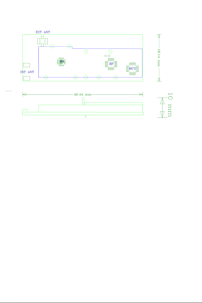
Mechanical Drawing
Electrical Characteristics
PINOUT
PIN Function
1 GND
2 VCC (Transmit)
3 Sync O.C.
4 Test_0
5 Trig
6 N.C.
7 Sync
8 COMTX
9 Reset
10 Test_2
11 Test_3
12 Test_1
13 TTL
14 RMTE
15 COM RX
16 +3V CPU

RMI3
9
www.profoto.com
Recommended Operating Conditions
Parameter Min Max Unit
DC Supply 2.7 3.5 V
Current 0.18 A
Temperature -10 +55 °C
Humidity 0 90 % rel n.c
Interface Description
The interface to the host system is implemented as a 16 pin male connector.
The part used on the RMI3 module is anAMP Micro-MaTch (P/N: 8-215464-6).
The recommended matching female connector is P/N: 8-215079-6. It is recommended
to connect the module with a female header mounted in through holes. This allows for
optimum space saving and leaves the antenna connector easily accessible.
UART Serial Interface
The UART is using pins 1,8 and 15.To connect to an RS232 line you must use aTTL level
converter (a dongle from B&BElectronics is recommended) from 3.3Vor use the ProfotoAir
USBdongle which mateswith anRMI3 moduleand provides aUSB interfaceto acomputer.
Serial characteristics:38400. 8,N,1 (no flow control)
NOTE!
Connecting the module to an RS232 line without a line level converter may
damage the module.
For a list of available commands please refer to the RUF documentation.
Reset Interface
The following conditions will lead to a reset on the Promote RMI3 module:
• Power on reset
• Low voltage (Brown Out) detected from internal supervisory circuit
• Reset by Software
• External reset through reset pin

RMI3
10
www.profoto.com
RF Characteristics
Parameter Min Typ. Max Unit
Frequency range 2404 2480 MHz
Frequency stability -25 +25 kHz
Output power EU/US 8.7 8.9 9.3 dBm
Output power Japan 5.4 6.2 8.7 mW
Output power USA/Canada 9.2 9.8 11.2 dBm
Channel list
Channel Air Ch # Frequency Unit Comment
1 1 2403.999 MHz
2 9 2406.998 MHz
3 2 2411.997 MHz
4 - 2414.996 MHz Only FHSS
5 3 2416.996 MHz
6 4 2421.994 MHz
7 5 2426.993 MHz
810 2429.992 MHz
911 2432.992 MHz
10 12 2435.991 MHz
11 13 2438.990 MHz
12 -2441.990 MHz Only FHSS
13 62446.988 MHz
14 14 2451.321 MHz
15 72453.987 MHz
16 15 2456.653 MHz
17 16 2459.652 MHz
18 17 2462.318 MHz
19 18 2465.317 MHz
20 19 2468.316 MHz
21 20 2471.316 MHz
22 -2474.315 MHz Reserved
23 82479.314 MHz
Note:Channel 4, 12 is only used for frequency hopping.Channel 22 is not currently used.

RMI3
11
www.profoto.com
Important Integration Notes
Profoto’sRMI3has beendesigned toallow foreasy integration witha widerange ofdevices.
There are some key factors you need to consider when integrating the module.
Mechanical Integration
The module needs at least 10 mm clearance in order to fit. This is the maximum
height with consideration to the connector pins. On the module’s backside there
is a test point underneath the antenna which must be protected from user access.
The module should arrive with a label with the serial number printed on it, which should
cover the test point.

RMI3
12
www.profoto.com
Electrical Integration
The minimum connections needed for operation are:
PIN Function Comment
1 GND Digital ground
2 VCC Transmit mode
5 Trig Active high
7 Sync Active high
In order to update the firmware the following pins is needed in addition to the ones
mentioned above:
8COMTX Transmit to host
9 Reset
15 COM RX Receive from host
16 +3V CPU CPU power supply
Antenna Integration
The Promote RMI3 module is available in one hardware configurations and several
software configurations. RMI3 uses an on board chip antenna. The use of any other
antenna is not approved and will break the modular approval.
All data are to be considered as nominal and Profoto reserves the right to make changes without further notice.

RMI3
13
www.profoto.com
Regulatory Information
World-wide Usage of Radio Spectrum
The RMI3 operates on the license-free 2.4GHz ISM band for SRD (Short Range Devices).
This band may be used in most parts of the world.Regional restrictions may apply.
NOTE!
Refer to national regulations for the region where the RMI3 module shall be
operated and make sure that they are followed.
Europe
The RMI3 module is in conformity with the essential requirements and other relevant
requirements of the Radio Equipment Directive (2014/53/EU).
Please note that every end product using the RMI3 module will need to undergo EMC
testing according to EN 301 489-17V3.1.1 (or later).
For RF,conduced test results can be inherited from the RMI3 test report to the end product
using RMI3. Limited EN 300 328 V2.1.1 (or later) testing for radiated spurious emission
is necessary and the test must be repeated with the end product using the RMI3 module.
FCC (USA)
This device complies with Part 15 of the FCC Rules. Operation is subject to the following
two conditions:
1.This device may not cause harmful interference, and
2. This device must accept any interference received, including interference that may
cause undesired operation.
Warning (Part 15.21)
Changes or modifications not expressly approved by the party responsible for
compliance could void the user’s authority to operate the equipment.
Integration instructions for host product manufacturers according to KDB 996369
D03 OEM Manual v01
2.2 List of applicable FCC rules
15C
2.3 Specific operational use conditions
This module is approved for use in portable and mobile applications.Integrators
must supply operating instructions for end users and installers to satisfy RF exposure

RMI3
14
www.profoto.com
compliance requirements are met.Integrators and installers must also make sure that
compliance with Part 15B are ensured.
2.4 Limited module procedures
This module is not shielded and therefore requires radiated emissions tests in each new
host product.
2.5 Trace antenna designs
N/A,the module does not use a trace antenna, it uses a SMT chip antenna.
2.6 RF exposure considerations
WARNING:The RMI3 device radiates radio frequency energy at a level below the
United States FCC radio frequency exposure limits.Nevertheless,this device should be
used in such a manner that the potential for human contact during normal operation
is minimized.For hand held operation,this device has been tested and meets FCC
RF exposure guidelines when the device is positioned a minimum of 1.0 cm from the
body.For on camera mounted operation,this device has been tested and meets FCC
RF exposure guidelines when the device is positioned a minimum of 2.0 cm from the
head and must not be co-located or operating in conjunction with any other antenna or
transmitter.As long as the two conditions above are met,further transmitter testing will
not be required.However,the OEM integrator is still responsible for testing their end-
product for any additional compliance requirements required with this module installed
(for example,digital device emissions, PC peripheral requirements,etc.).
2.7 Antennas
Antenna is Fractus Compact Reach Xtend,P/N:FR05-S1-N-0-102.
2.8 Label and compliance information
IMPORTANT NOTE:
The RMI3 module is labelled with its own FCC and IC ID. If the FCC and IC ID:s is not
visible when the module is installed inside another device,then the outside of the device
into which the module is installed must also display a physical label or eLabel referring
to the enclosed module.In that case the end product must be labelled in a visible area
with the following: Contains FCC ID:W4G-RMI3 and IC: 8167A-RMI3
FCC ID:W 4G-R MI 3
IC :8 16 7A -R MI 3
MODEL: PCD0188-0000 Rev C1
202-SMH035
R
FCC ID:W 4G-R MI 3
IC :8 16 7A -R MI 3
MODEL: PCD0188-0000 Rev C1
202-SMH035

RMI3
15
www.profoto.com
IMPORTANT NOTE:
In the event that these conditions cannot be met (for certain configurations
or co-location with another transmitter),then the FCC and Industry Canada
authorizations are no longer considered valid and the FCC ID and IC Certification
Number cannot be used on the final product.In these circumstances, the OEM
integrator will be responsible for re-evaluating the end product (including the
transmitter) and obtaining a separate FCC and Industry Canada authorization.

RMI3
16
www.profoto.com
IC Compliance Statement (Canada):
This Device complies with Industry Canada License-exempt RSS standard(s). Operation
is subject to the following two conditions:
1) this device may not cause interference,and
2) this device must accept any interference, including interference that may cause
undesired operation of the device.
Le présent appareil est conforme aux CNR d’Industrie Canada applicables aux appareils
radio exempts de licence.L’exploitation est autorisée aux deux conditions suivantes:
(1) l’appareil ne doit pas produire de brouillage, et
(2) l’utilisateur de l’appareil doit accepter tout brouillage radioélectrique subi,
même si le brouillage est susceptible d’en compromettre le fonctionnement.
Under Industry Canada regulations,this radio transmitter may only operate using an
antenna of a type and maximum (or lesser) gain approved for the transmitter by Industry
Canada.
IC RF Exposure limits
The RMI3 device complies with the IC RSS-102 radiation exposure limits set forth for
an uncontrolled environment.For hand held operation,this device has been tested and
meets IC RF exposure limits when the device is positioned a minimum of 1.0 cm from the
body.For on camera mounted operation,this device has been tested and meets IC RF
exposure limits when the device is position a minimum of 2.0 cm from the head’
Limites d’exposition RF IC
Le dispositif RMI3 est conforme aux limites sur l’exposition aux rayonnements IC RSS-
102 définies pour un environnement non contrôlé.En mode manuel, ce dispositif a été
testé et respecte les limites d’exposition IC RF lorsque ce dernier est placé à au moins 1
cm du corps.Pour un fonctionnement sur caméra,ce dispositif a été testé et respecte les
limites d’exposition RF IC lorsque ce dernier est positionné à au moins 2 cm de la tête.
Japan
Japanese Radio Law and Japanese Telecommunications Business Law Compliance.
This device is granted pursuant to the Japanese Radio Law (電波法 ) and the Japanese
Telecommunications Business Law (電気通信事業法) This device should not be
modified (otherwise the granted designation number will become invalid).
R 202-SMH035

ProfotoAB
Box 1264
SE-172 25 Sundbyberg
SWEDEN
Phone +46 8 447 53 00
www.profoto.com
Profoto RMI3,Printed in Sweden
Table of contents


