ProGear E-FREE TRIKE User manual

NOTE: This manual may be subject to updates or changes. Up to date manuals are available through our website at www.progearbikes.com.au
Only be to assembled by a skilled bicycle mechanic
Read all instructions carefully before using this product. Retain this owner’s manual for future
reference.
E-FREE TRIKE OWNER’S
MANUAL

2
TABLE OF CONTENTS
1. IMPORTANT SAFETY INSTRUCTIONS 3
2. BATTERY CARE AND SAFETY 4
3. PARTS LIST 6
4. ASSEMBLY INSTRUCTIONS 8
5. COMPONENTS 17
6. ELECTRONICS 20

3
1. IMPORTANT SAFETY INSTRUCTIONS
Failure to obey all of the warnings and instructions contained in this manual may result in serious injury, or
permanent damage to your bike.
Always wear a properly fitted and fastened helmet when riding. This is required by law in most
states and is an important safely precaution. Failure to wear an approved safely helmet can result in
severe injury or death.
Check your helmet for proper fit and damage before each ride.
Always obey all traffic laws.
The purchaser, owner, and/or riders of this cargo bike are directly responsible for knowing and
obeying all local, state and federal laws regarding the riding and use of this cargo bike
Always ride cautiously, maintaining complete control and a reasonable speed (<20km/h).
The rider should hold the handlebars and stop before get on or off
Sitting securely when riding.
Slow down the speed to 10km/h or less before turning the corner, in order to avoid rolling over
This bike is not suitable for stunt riding, jumping, competition, or racing.
Always check that brakes and throttle are functioning properly before each ride.
Only one rider at a time.
Carrying more than 4 objects in the basket may interfere with your control of the cargo bike, and can
result in loss of control.
Do not ride at night or in conditions when visibility is impaired, unless you install head lamps and tail
lamps that make you visible to all pedestrians and vehicles.
Wet weather significantly detracts from brake performance. Always allow a longer distance for
safely stopping in the rain, or on a wet or icy road surface.
This product should not be used by minors without adult supervision.
Do not modify the bike
Do not tow or pull with the cargo bike. Do not allow the cargo bike to be towed or pulled.
Keep fingers away from moving parts and chain.
Always park in right place.
Avoid high speed sharp turns, as your cargo bike may tip over.
Make sure that there is an enough braking distance when with cargo.
Must use rear brake every time when braking.
Some localities require that the owner or rider equip their bike with a horn, bell, or other sound
making device to use for warning others of your approach.
Check handlebar and seat adjustments before riding.
Check all axle, motor mounting, and drive system mounting nuts.
Check your tires for cuts, exposed casing, casing cords, and proper inflation before each ride.
This bike is not recommended for competition, stunt, any aggressive or off-road riding.
Ensure you wear safe footwear and keep loose articles of clothing clear of moving parts on your E-
Bike while riding.

4
2. BATTERY CARE AND SAFETY
Do not disassemble the battery pack and modify the unit or your warranty will be void and you will
be responsible for the modification.
Make sure that the battery pack has been fully charged before first use, and remove the charger
after fully charging. Turn the main battery switch off while charging or not using.
Check that all electrical connections and mechanical parts are securely locked and fastened before
use.
The performance and mileage of the unit will be varied with the battery condition, temperature,
terrain, wind speed, tire pressure, rider weight and the maintenance.
Always handle the battery pack with care and do not drop it.
Do not connect the terminals of battery pack with any foreign object.
1. Battery Charging
Battery should be charged timely after riding the power assist vehicle. Lithium battery of the Company should
be charged with designated charger. Connect the output plug to the charger and then connect the charger
to 240V alternating current power supply. Battery can be used after charging 6-7 hours until the charging
indicator light turn from red to green.
2. Battery Discharging
Riding process of the power assist vehicle is the process of battery discharging. Users are not permitted to
over discharging the battery. Over discharging may cause severe damage to battery life. When instrument
displays that the battery is under voltage, the controller will stop power supplying at any time.
3. Battery Storage & Additional Charging
Reserve of electricity will somewhat lose when storing or during the transportation process. Battery should
be additional charged before use. Charging method is as above.
4. Battery Use, Maintenance & Attention
4-1 Never put battery close to heat source of high temperature;
4-2 Charging environment is better to be below 37℃;
4-3 Avoid charging under direct sunlight;
4-4 Resolutely use designated charger to charge the battery;
4-5 Short circuit is not allowed at battery charge port;
4-6 Never put battery in wet places or in water;
4-7 Never randomly dismantle the battery or do any unauthorized modification;
4-8 Never impose external forces on the battery or drop it from high places;
4.9 When battery is not in use, it should be fully charged and stored in a dry and cool place. Places within
1m around the battery should be free of inflammables and is insulating. Battery should be kept away from
heavy load and children. Complete additional charging should be conducted every 2 months.
5. Special Warning:
a) Never clean the vehicle with hydraulic monitor which may cause damage to electrical components
due to water intake.

5
b) If the product smokes or burns when damaged by external forces, put it out with dry-chemical fire
extinguisher or sandy soil.
c) Although the lithium battery is environmental friendly product, it also contains various kinds of
chemical substances. When it is broken due to aging, it may pollute the environment. Therefore,
please discard it as useless within 36 months since the date of purchase, and give it to skilled
company for professional treatment.
6. Disclaimers
a) no responsibility for any damages caused by nonconforming the requirements in application
instruction manual
b) no responsibility for any damages caused by any unauthorized modification
c) no responsibility for any damages caused by force majeure

6
3. PARTS LIST
PART
DESCRIPTION
1
Handlebar
2
LCD Display Panel
3
Brake Lever
4
Gear Shift
5
Disc Brake
6
Gear Freewheel
7
Rear Derailleur
1
2
3
4
5
6
7

7
PART
DESCRIPTION
8
Front Frame
9
V-Brake
10
Front Fork
11
Front Wheel Set with Motor
12
Chain Cover & Chain
13
Chain Wheel and Cranks
14
Pedal
15
Real Wheel Set
16
Wheel Reflector
17
Basket
18
Rear LED Light
19
Li-battery
20
Seat Post Clamps
21
Seat Post
22
Saddle
8
9
10
11
12
13
14
15
16
17
18
19
20
21
22
8
4. ASSEMBLY INSTRUCTIONS
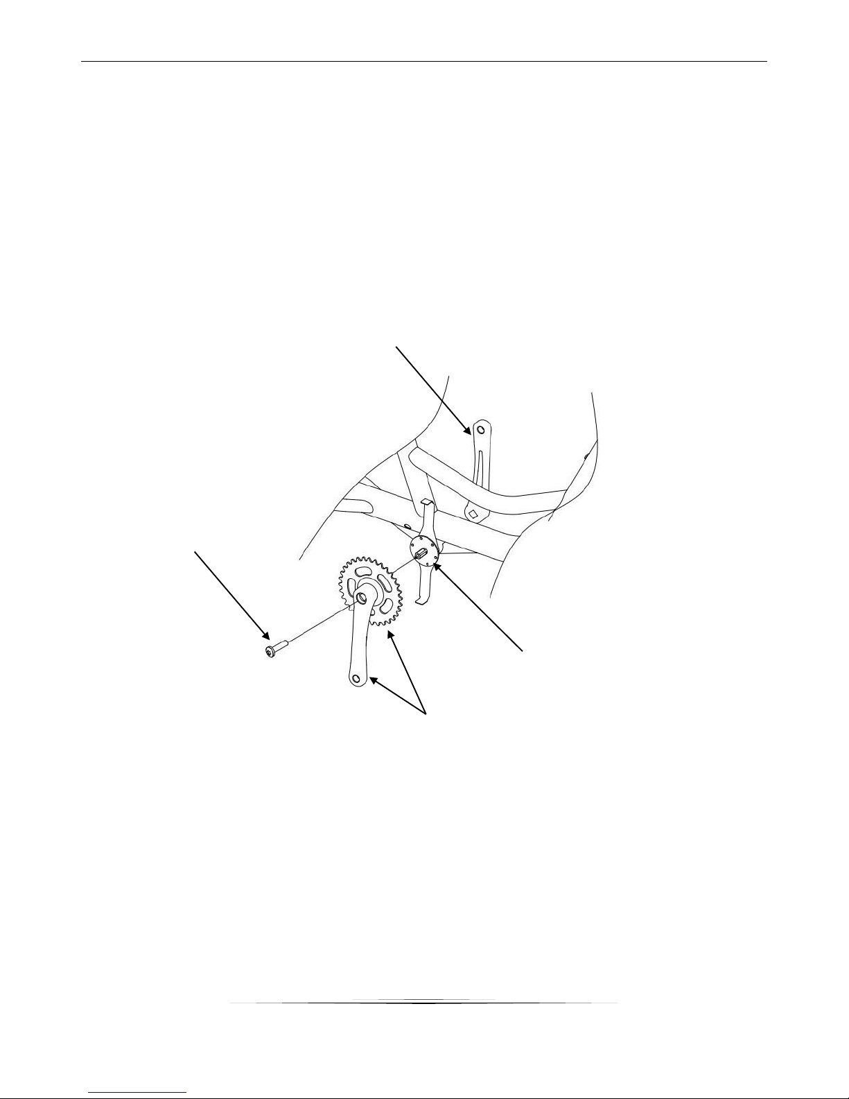
STEP 1 – Chain Wheel and Crank Assembly
a) Attach electromagnetism sensor piece into the middle axle. Ensure the sensor piece is assembled
towards the correct riding
b) direction.
c) Assemble the chain wheel and crank to middle axle and secure with fixing bolts.
Crank
Fixing bolts
Chain wheel and crank
Electromagnetism
Sensor piece
Figure 1
9
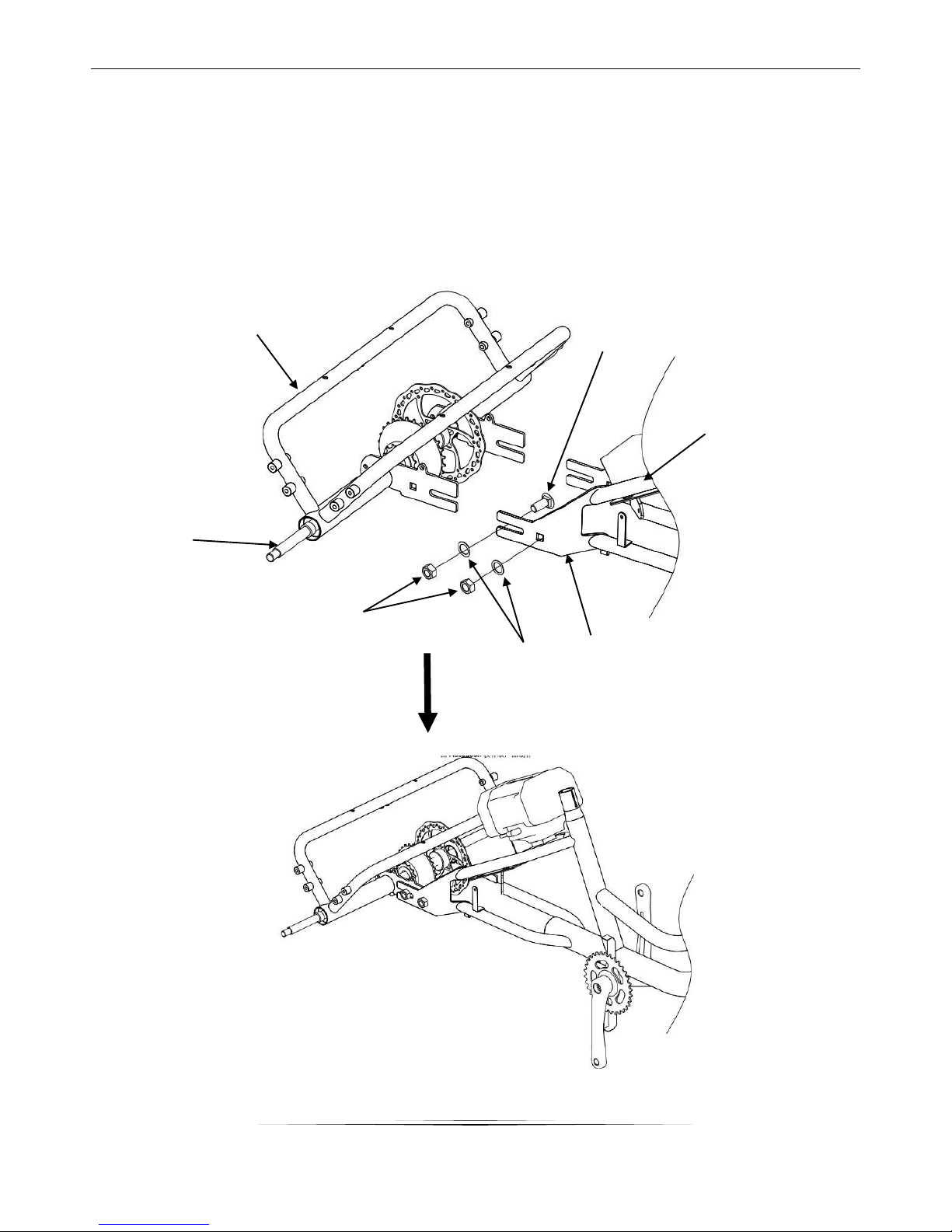
STEP 2:
a) Refer to Fig.2: Connect the front frame and rear frame with:
- Square neck bolts
- Nuts
- Washers
Figure 2
Rear frame
Front frame
Transmission
Axle
Front frame
Bracket
Nut
Washer
Square neck bolt
Figure 3
10
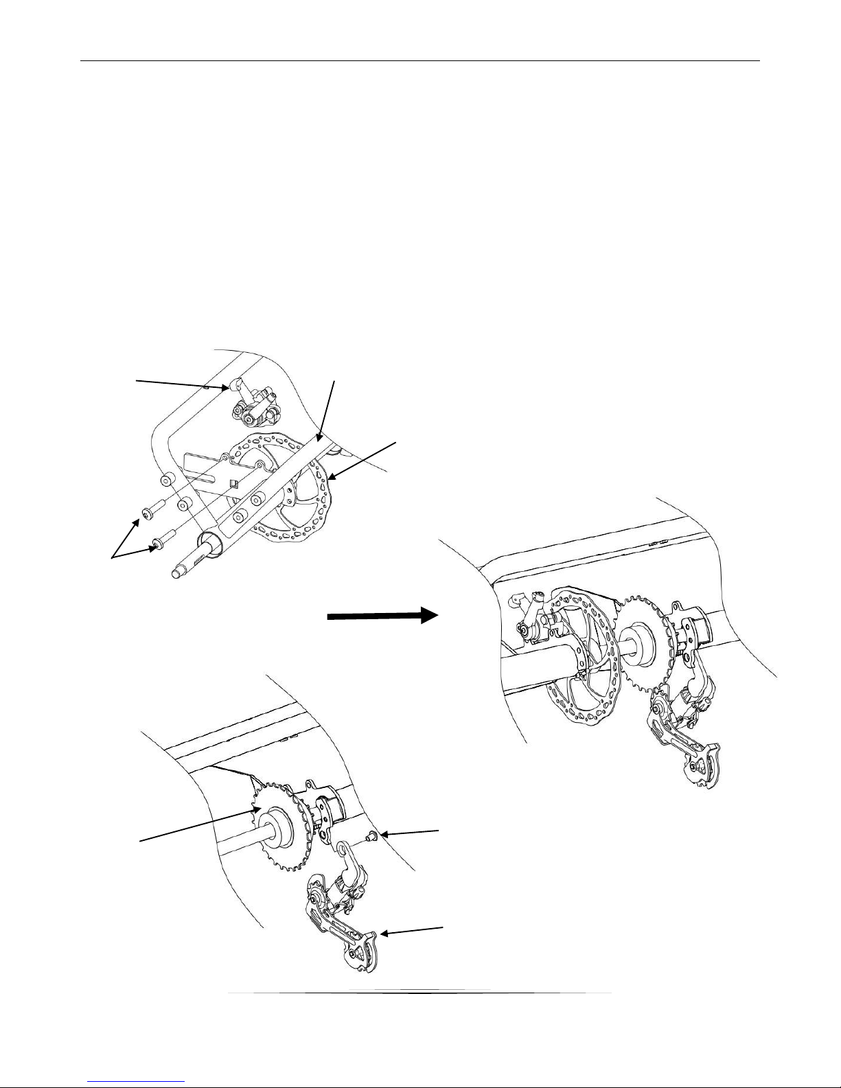
STEP 3:
a) Refer to Fig. 4 & 5: Assemble the disc brake and rear derailleur onto the rear frame.
b) Assemble disc brake disc on the rear axle first.
c) When bolting on the disc brake caliper ensure there is even clearance between both sides of the
disc pads and the disc.
d) Check the rear derailleur adjustment on attached sheet.
Figure 4
Figure 5
Figure 6
Assembled Image
Disc Brake
Caliper
Rear frame
Disc brake disc
Screw
Gear freewheel
Derailleur
Screw
11
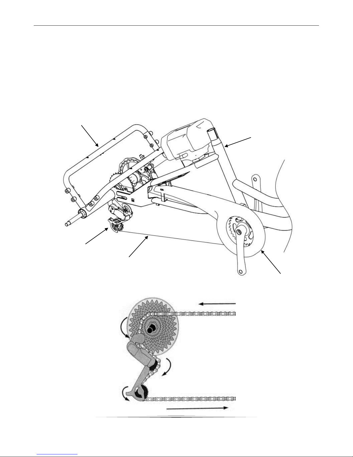
STEP 4: Chain and Chain Cover Assembly
a) Refer to Fig. 7 and Fig. 8: Assemble the chain (Gear adjustment see Attachment 1 and 2) and
secure the chain cover to frame with screws
b) A chain breaking tool will be required to re-rivet the chain once fed through the gear system (no
joining link in this chain)
Derailleur
Chain
Rear frame
Front Frame
Chain cover
Figure 7
Figure 8
12
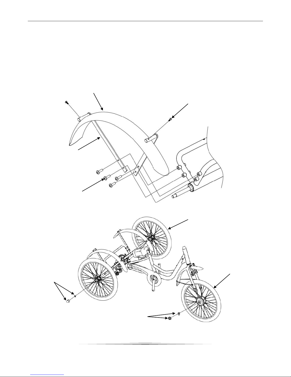
STEP 5: Fender and Front Chain and Chain Cover Assembly
a) Refer to Fig. 9: Secure the front and rear fenders to the correct position on frame with screws.
(Assembly of fender is optional)
b) Refer to Fig. 10: Attach the front and rear wheelset with nuts and washers. (Note: Cable of the front
wheel motor should be on left side)
Figure 9
Figure 10
Rear fender
Screw for fixing
attaching fender
Screw for fender stay
Fender stay
Rear wheelset
Front wheelset
with motor
Locking nut
and washer
Cap nut and
washer

13
Handlebar stem
Gear Cable
Brake cable
Brake lever
Handlebar
Figure 11
STEP 6: Handlebar and brake cable adjustment
a) Refer to Fig. 11: Insert the handlebar stem
into head tube of front frame
b) Adjust head stem height and tighten step
bolt.
c) Adjust the handle bar angle and secure into
place.
d) Adjust the front and rear brake cables to
ensure brake cables are fitted correctly.
(For gear adjustment see attachment 1 and
2).
STEP 7: Basket Assembly
e) Refer to Fig. 12: Attach the basket to the
rear frame with:
- Basket layer
- Screw
- Nuts
Figure 12
Screw & nut
Basket Layer
Basket
Stem bolt

14
STEP 8: Fender and Front Chain and Chain Cover Assembly
a) Attach saddle to seat post clamp and tighten slightly.
b) Insert the seat post into the seat tube and tighten bolts (Note: Safety line should be covered)
c) Adjust seat angle and retighten seat clamp
Figure 12
Saddle
Seat Post
Seat Post
Clamp
Seat Tube
15
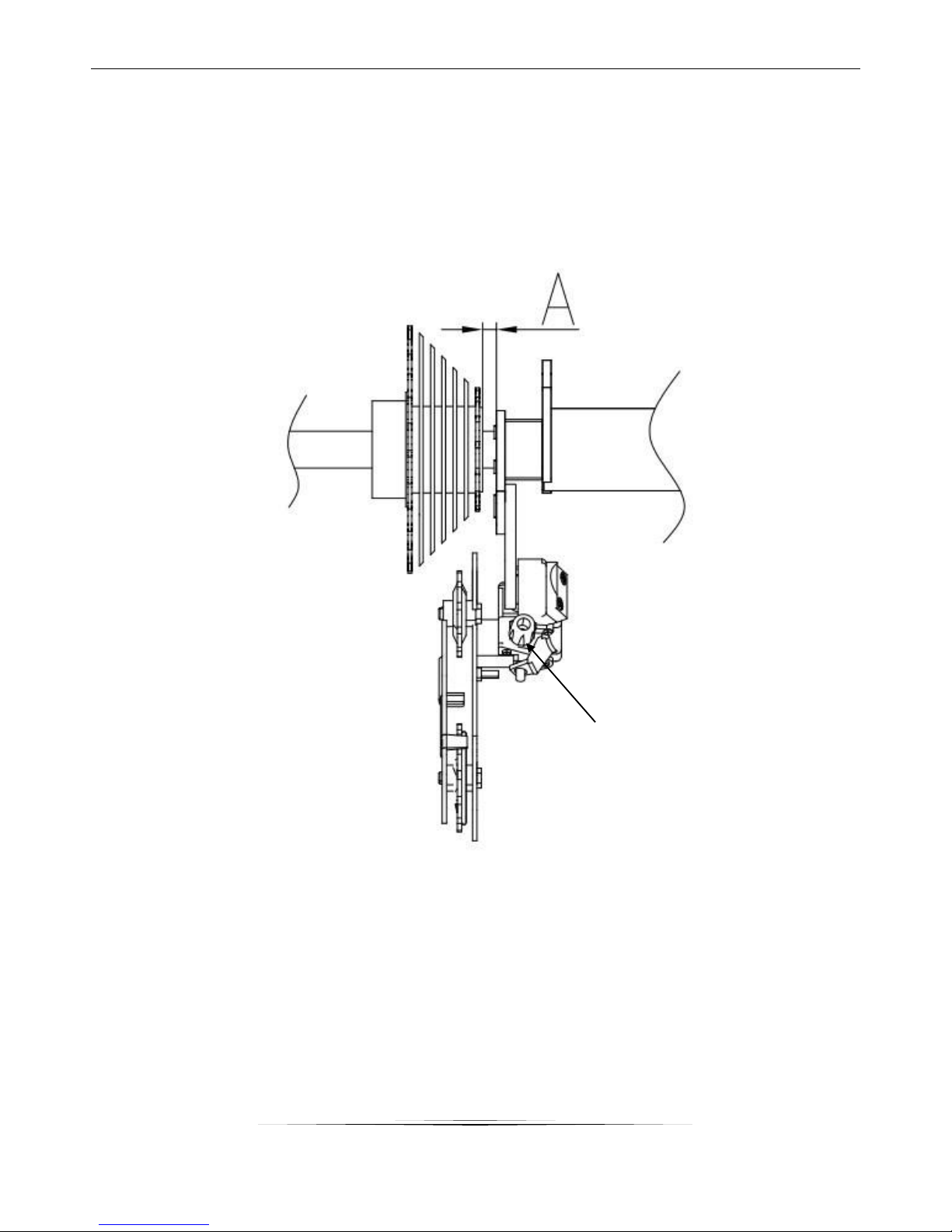
Attachment 1
Refer to Fig. 13: Adjust the position of freewheel to make sure the distance between gear freewheel and
derailleur is equal to 5~6mm.
Feed the inner gear cable through the derailleur ferral and secure with lock nut.
Figure 13
Derailleur Ferral

16
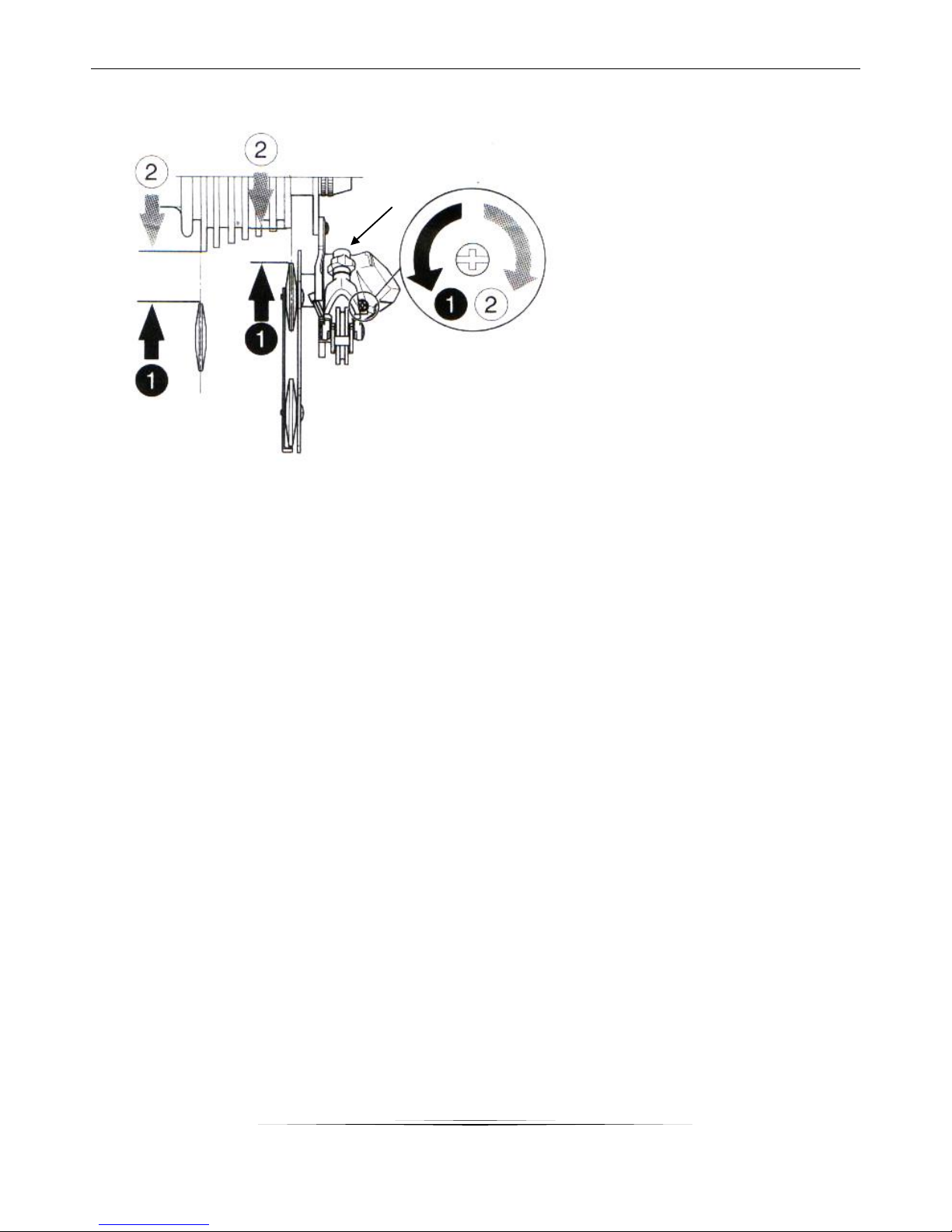
Attachment 2
Figure 14
4
Cable Tension: 5 – 7 N.M
Pull
Figure 15
Refer to Fig.15:
a) Turn the top (marked H) adjustment screw to so that the guide roller is below the outer line of the
smallest sprocket when looking from the rear.
b) Turn the low (marked L) adjustment screw so that the guide pulley moves to a position directly
below the largest sprocket. Ensure it does not over shift.
Note: these screws are stop screws only so the derailleur does not over shift.
Adjust the screw
towards below
Guide Roller
17
Figure 16
Refer to Fig. 16:
Adjust the tightness of inner cable to
ensure the derailleur shifts smoothly.
If the cable is too loose:
The derailleur will not upshift to the
larger sprockets
If the cable is too tight:
The derailleur will not downshift to
the smaller sprockets

18
5. COMPONENTS
Disc-Brake Adjustment
The city bike uses the Australian style of the brake system. The right brake lever is for the front wheels while
the left for rear wheel.
Important:
Brake pad wear limit: replace the brake pads before the friction material has been worn down to less than
2.5 mm.
1. Open the brake lever and place the nipple end of the short brake cable into the lever, then close the lever.
Secure the ferrule against the lever using the cable adjusting barrel.
2. Depress the brake lever about 10 times as far as the grip to check that everything is operating correctly
and that the shoe clearance is correct before riding the bike.

19
Tires
Bicycle tires are available in many designs and specifications, ranging from general-purpose designs to tires
designed to perform best under very specific weather or terrain conditions. If, once you’ve gained
experience with your new bike, you feel that a different tire might better suit your riding needs, your
dealer can help you select the most appropriate design.
The size, pressure rating, and on some high-performance tires the specific recommended use, are marked
on the sidewall of the tire .The part of this information which is most important to you is Tire Pressure.
WARNING: Never inflate a tire beyond the maximum pressure marked on the tire’s sidewall. Exceeding
the recommended maximum pressure may blow the tire off the rim, which could cause damage to the
bike and injury to the rider and bystanders.
The best and safest way to inflate a bicycle tire to the correct pressure is with a bicycle pump which has a
built-in pressure gauge.
Tire pressure is given either as maximum pressure or as a pressure range. How a tire performs under
different terrain or weather conditions depends largely on tire pressure. Inflating the tire to near its
maximum recommended pressure gives the lowest rolling resistance; but also produces the harshest ride.
High pressures work best on smooth, dry pavement. Very low pressures, at the bottom of the
recommended pressure range, give the best performance on smooth, slick terrain such as hard-packed
clay, and on deep, loose surfaces such as deep, dry sand.
Tire pressure that is too low for your weight and the riding conditions can cause a puncture of the tube by
allowing the tire to deform sufficiently to pinch the inner tube between the rim and the riding surface.
Tire Valves
The tire valve allows air to enter the tire’s inner tube under pressure, but doesn’t let it back out unless you
want it to. There are primarily two kinds of bicycle tube valves used in Australia: the Schraeder Valve and
the Presta Valve. The bicycle pump you use must have the fitting appropriate to the valve stems on your
tire.
The tires use a Schraeder valve, which is like the valve on a car tire. To inflate a Schraeder valve tube,
remove the valve cap and push the air hose or pump fitting onto the end of the valve stem. To let air out of
a Schraeder valve, depress the pin in the end of the valve stem with the end of a key or other appropriate
object.
1. Check whether rim is deflected or loosened and whether spoke is loosened or broken before riding. If any
unusual condition, ask professional technician for adjustment or change.
2. Please change the tyre if cover tyre grain is worn and torn.
3. Please guarantee proper PSI. When inflating, please take nominal value of cover tyre as reference. Never
inflate over the pressure or under the pressure.
Caution: Please make sure the contact area of tyre and ground should not be less than 10cm while riding.

20
Change of Pedals
Left pedal and right pedal should be clarified when changing. Pedal spindle is usually engraved with “R” and
“L”.
Tool: 15mm open end wrench
When changing Right side, clockwise rotation is to lock and anticlockwise rotation is to disassemble.
When changing Left side, clockwise rotation is to disassemble and anticlockwise rotation is to lock.
Tightening torque should be more than 18N.m
Table of contents
Other ProGear Bicycle manuals


