Progres Agronic 4500 User manual

Sections contained in the manual:
‒ Dimensions
‒ Technical characteristics
‒ Location of the connections
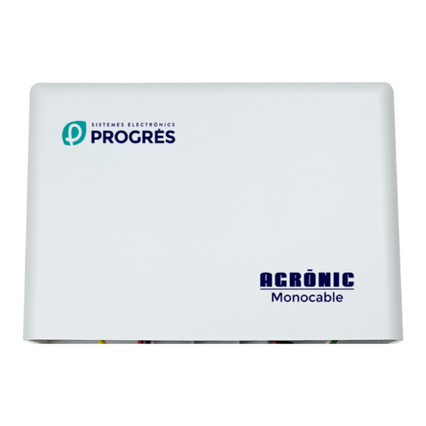
‒ Connection
‒ Installation of options
‒ Recommendations
The Programming, Manual Actions and Query sections
are detailed in the User Manual.
The Parameters and Coding of inputs and outputs
sections are detailed in the Installer Manual.
The Communication Parameters section is detailed in
the Communication Manual.
ASSEMBLY AND CONNECTION MANUAL
VERSION 1
AGRÓNIC 4500

Welcome to the Agrónic 4500 manual.
We are pleased to have your experience and skills to carry
out the installation of the Agrónic 4500.
This document will guide you in the process of installing
Agrónic on the farm or electrical panel. Providing details
about the dimensions of the controller, and wiring of the
dierent connection options.
¡Thanks for you dedication!

Index
1 Dimensions.......................................................................................................... 4
2 Technical characteristics .................................................................................... 5
3 Situation of the connections .............................................................................. 6
3.1. Box format ................................................................................................. 6
3.2. Built-in format ........................................................................................... 7
4 Connection .......................................................................................................... 8
4.1. Power connection...................................................................................... 8
4.2. Ground connection.................................................................................... 8
4.3. Connecting the digital inputs ................................................................... 9
4.4. Connection of the outputs........................................................................ 9
4.5. Diesel enginge connection...................................................................... 11
4.6. Connection of the expansion modules (EM) .......................................... 12
5 Installation of options....................................................................................... 13
5.1. Double voltage option............................................................................. 13
5.2. Latch option............................................................................................. 15
5.3. Analog inputs and outputs option.......................................................... 17
5.4. Agrónic Monocable / Radio option......................................................... 18
6 Recommendations............................................................................................ 19

4Assembly and connection manual | Agrónic 4500
1 DIMENSIONS
Box formatBuilt-in format
Agrónic location
Install the Agrónic at the appropiate height and
position for good handling. Avoid as much as possible
the direct incidence of the sun, humidity, dust and vi-
brations.
Avoid being close to elements that generate interferen-
ce and may aect proper operation.
In the box format, the controller is housed in a
hermetic box (IP 65) with a transparent front cover for
the keyboard/display, and a opaque cover for housing
of the connections.
To mantain the tightness, it is necessary to leave the
covers always closed and install the cable glands,
which are included with the controller, in the outlets
of the cables.
The wall fastening is done by the two pierced pieces
in the upper corners. The fastening elements can be 2
self-tappin screws (3.5 x 38 mm - DIN 7981) and 2 plugs
6 x 30 mm (SX 6x30).
In the built-in format, a hole will be made in the front
of the cabinet or desk according to the measurements
and it will be held by the screws in the corners, using
the four pieces that are suplied with the controller (4
M3 x 12 mm (DIN 84) screws, 4 M3 nuts (DIN 934) and 4
metal sheets of 20 x 20 x 1 mm).
Mounting

5
Assembly and connection manual | Agrónic 4500
Voltage 12 Vdc - 24 Vdc
Energy consumption Less than 12 W
Fuse Entrance Thermal (PTC) 1,1 Amp. at 25 °C, self-resetting
Overall power supply
Voltage From 12 a 24 Vdc ó Vac (maximum 30 V)
Fuse “R+” input Thermal (PTC) 6,0 Amp. at 25 °C, self-resetting
Power supply outputs
Memory Without maintenance, 10 years for parameters, programs and registers in memory in FLASH
memory.
Clock 10 years without power
Memory Backup and Clock
Digitals
Number 24, expandable to 40, 56, 72, 88 and 104.
Type By relay contact, with 24 Vac potential (external transformer).
Límits 30 Vac / 30 Vdc, 1 Ampere, 50-60 Hz, CAT ll (per ouput)
Analog /
Pulsed (option)
Number 5 or 10
Type 4-20 mA (with galvanic isolation)
All the outputs have double insulation with respect to the network input.
Outputs
Temperature -5 °C a 45 °C
Humidity < 85 %
Altitude 2000 m
Pollution Grade 2
Atmosphere
Box model De 3,2 kg a 6,3 kg
Built-in model De 4,0 kg a 5,0 kg
Weight
This symbol indicates that electrical and electronic equipment must not be disposed of with household waste at the end
of its useful life. The product must be taken to the corresponding collection point for recycling and proper treatment of
electronic equipment in accordance with national legislation.
Digital
sensors
Number 12
Type Optocoupled, operate at 12 ot 24 Vcc/Vac
Analog
(option)
Number 5 ó 10
Type 4-20 mA, (with galvanic isolation)
Number 1 ó 2
Type 0-20 V (with galvanic isolation)
Inputs
It complies with Directive 89/336/CEE for Electromagnetic Compatibility and Low Voltage Directive
73/23/CEE for Product Safety Compliance. Compliance with the following specifications was
demonstrated as indicate in the Oicial Journal of the European Communities.
Declaration of conformity
Protective Earth
terminal Danger, risk of
electric shock Ground Terminal Double insulation
Symbols that may appear on the product
2 TECHNICAL CHARACTERISTICS

6Assembly and connection manual | Agrónic 4500
3 SITUATION OF THE CONNECTIONS
3.1. BOX FORMAT
To make the connection in the controller with box
format, remove the bottom cover to access the connec-
tors.
For the cable entry, the necessary knockouts must
be removed (do it with connection cover in place and
screwed, to avoid possible breakage).
The connectors and antennas for the rest of the options
are located on the right side.
It is advisable to connect the cables to the terminals
with connection terminals, which are included with the
controller. (The terminals accept cables up to 2.5 mm2
in section).
Box format for models with 24 + 16 outputs

7
Situation of the connections | Built-in format
Assembly and connection manual | Agrónic 4500
3.2. BUILT-IN FORMAT
In the built-in format, access the rear face located
inside the desk or cabinet. Here we find the connectors
for the power supply, the inputs, the outputs for the
models of 24, 40 ...
In addition, when there are options installed, there
may be the connectors for the antennas of the
AgroBee-L options or for the modem of Wi-Fi. On the
sides there can be the connector for the USB port and
the RS-485 port.
Built-in format Box format to expand to models of
56, 72, 88 and 104 outputs

8Assembly and connection manual | Agrónic 4500
4 CONNECTION
4.1. POWER CONNECTION
4.2. GROUND CONNECTION
Power
Power is 12 Vdc for all models.
In installations with a solar panel, generator set or diesel
motor pump, it will be connected to the 12 Vdc battery.
Ground
The installation must be carried out in accordance with current regulations for electrical installations. The protection of
the controller will not be ensured if it is not used as specified in this manual.
The Agrónic must be installed far from sources of interference such as frequency inverters, motors or power cables.
Sensor and communication cables should never pass next to alternating current cables and should preferably be
shielded. All the connection terminals of the Agrónic 4500 are pluggable, wich allows quick maintenance.
In 110 or 230 Vac systems, a 90-230 Vac / 12 Vdc (50-60Hz)
power supply is available as an accessory to connect the
controller. The socket outlet to which connect the power
should be easily accessible.
The power input has a self-resettable thermal fuse, it is
also protected against polarity inversion and overvolta-
ge peaks.
It is necessary to have an independnet magnetothermic
switch in the installation that protects the Agrónic 4500.
The general power and the transformer that power the
outputs will be connected at its output.
When a diesel engine is running avoid disconnect the
battery as the alternator would considerably increase
the supply voltage and damage the Agrónic.
The ground terminal is located next to the power
terminals. Its function is to direct possible electrical
sparks generated by storms to the ground and that may
enter through the input and output cables; arc striking
in the internal gas discharge tube occurs from 90 volts.
It is very important to connect this socket, independent-
ly, for a complete protection of the controller.
In the built-in model there is an additional earth connec-
tion on the side of the metal box in case it is necessary
to derive i to earth.
The earth connection must be distinct and separated
from the grounding of drives or motors.

9
Connection | Connecting the digital inputs
Assembly and connection manual | Agrónic 4500
4.3. CONNECTING THE DIGITAL INPUTS
4.4. CONNECTION OF THE OUTPUTS
Both the digital inputs and the relay outputs are exter-
nally powered at 12 Vdc or 24 Vac.
The digital inputs are galvanically isolated by optocou-
plers from the rest of the circuit.
All the outputs are prepared to work both at 12 and 24
volts in alternating or continuous (do not power with
voltages higher than 30 volts).
For 24 Vac operation, an external transformer with 24
Vac output with double insulation must be available
according to the UNE EN61010 standar.
The input for powering the outputs is marked as “R+”
and “R-”.
The “AUX” terminal corresponds to the “R+” input
passed fhrough the power supply protection. It is used
to connect manual control auxiliary elements and relay
extensions.
The contacts of the devices connected to the digital
inputs must be free of voltage.
The controller has 12 digital inputs on the base, indicated
as D1 to D12 and a common marked as CD.
The solenoids of the electricvalves, the relays or the con-
tactors are connected between a common output “CR”
and the corresponding output between “R1” to “R104”.
The outputs are isolated from the internal circuit by
relays and protected by a varistor in each one.
The power supply to the outputs and the sensors are
protected by a self-resetting thermal fuse, also in the
section “Consult - Agrónic” it will indicate whether or
not there is voltage for the outputs. When there is a short
circuit in any of the outputs, the fuse will enter automa-
tically, limiting the output until the short circuit ends.
Digital inputs

10 Assembly and connection manual | Agrónic 4500
Connection | Power connection
24 Vac outputs (220 Vac installation)
12 Vdc outputs (12 Vdc installation)

11
Connection | Diesel enginge connection
Assembly and connection manual | Agrónic 4500
4.5. DIESEL ENGINGE CONNECTION
In installations where there is a motorized pump,
Agrónic can manage the start and stop manoeuvres.
To manage it, it uses four outputs (preheating, contact,
start and stop) and a digital input (oil pressure switch).
When connecting diesel engine starters, the following
details must be taken into account:
ENTRANCE
PA oil pressure switch. The pressure switch input can be
connected to any of the 12 digital inputs on the base. It
is not necessary to connect the DC digital common to
the pressure switch as it is done directly through the
motor chassis.
OUTPUT
The outputs deliver the battery positive. And additional
relay will be inserted in each of them to avoid damage
to the internal relays. The contact output will be
connected through the realy to the wire from the “15/54”
terminal of the key. It is the controller that is in charge of
giving and removing the contact, so the key must be le
in the rest position.
A supplementary relay will be inserted in the starting
output, with a capacity of 20 to 30 Amps, connected
checking its output with the cable from terminal “50” of
the key.
If the motor is stopped by an electromagnet, it will
be connected to the supplementary relay of the stop
output.
If the stop is made by cutting o the fuel with a solenoid
valve, it will be installed at the same inlet of the injector,
so that the stop is as quick as possible.
When the solenoid valve is normally open, it will
connect directly to the stop output. If the solenoid valve
is normally closed, it will be connected to the contact
output.
When there is preheating, it will be connected to the
relay for activation.
Diesel engine

12 Assembly and connection manual | Agrónic 4500
Connection | Connection of the expansion modules (EM)
4.6. CONNECTION OF THE EXPANSION MODULES (EM)
To connect the Expansion Modules (EM) it is necessary
to have the “RS485 EM Link” option installed.
The connection will be made with a 2-wire hose of
0.5mm minimum. The maximum distance between the
Agrónic and the last of the EM is 1200 meters.
The cable cannot be routed together with alternating
current cables or near devices that may produce electri-
cal interference (inverters and motors).
If more distance is needed, it is possible to add (“RS485
Repeater Option” (06741220) of through the “Radiomo-
dem Option”.
Expansion modules
It may be interesting to have a double sotp system for
greater safety, with the electromagnet for a quick and
eective stop, plus the eletromagnet normally closed
valve to cut o the fuel supply when there is a possible
break or incident.

13
Assembly and connection manual | Agrónic 4500
5 INSTALLATION OF OPTIONS
5.1. DOUBLE VOLTAGE OPTION
The dual voltage option is for installations where power
comes from a diesel generator. The Agrónic will start the
generator when it has to do an irrigation and will stop it
when finished.
The Agrónic is powered by the grups’s 12 Vdc battery.
The four outputs that give the orders to start and stop
the generator go to 12 Vdc, all the others go to 24 Vac
and are operational when the generator is running.
In the Agrónic 4500 base, the 12 Vdc outputs are R21,
R22, R23 and R24 (for any model).
The Agrónic can have two functions:
With start and stop management of the diesel engine. In
this case the diesel control is used with the outputs of
preheating, contact, start, stop and the digital input of
the oil pressure swith.
Will starting unit management incorporated in the
generator. In this case only one contact signal is neede.
To activate this operation, the start and stop times will
be ‘0’.
Diesel engine with generator set without control unit

14 Assembly and connection manual | Agrónic 4500
Installation of options | Connection of the expansion modules (EM)
Diesel engine with generator set with control unit

15
Installation of options | Latch option
Assembly and connection manual | Agrónic 4500
2-wire latch connection
5.2. LATCH OPTION
In installations where a very low energy consumption
is needed, latch valves are usually used. Latch solenoid
valves, also called impulse valves, work by locking their
hydraulic position in opening or closing, consuming
energy only at the moment of change. This allows
power to be powered by a battery only or by battery
and a solar panel. The calculation will be made taking
into account options and auxiliary installation systems.
The installer can prepare the controller to use latch
solenoid valves in the format of two or three wires and
the trip voltage at 12 or 22 volts. See the section “Para-
meters - Installer”.
When installing 3-wire models it will be necessary to in-
corporate in the installation a box of diodes, adequate
to the total number of outputs of the controller, to carry
out the connection of the start and stop commons. In
the 2-wire models is not necessary.
One of the two cables will be connected to the common
outputs “CR” and the other to the corresponding
output between “R1” to “R104”.
When the solenoid valve actuates hydraulically at the
inverse of the order given by the controller, this will
be inverted order by entering “Installer Parameters -
Varioius”.

16 Assembly and connection manual | Agrónic 4500
Installation of options | Latch option
3-wire latch connection
This model of solenoid valve has two commons, the
running one (normally red) will be taken to the diode
box, to one of the terminals marked “Start”, the stop
common (usually black) will be connected to a terminal
marked as “Stop”, the other cable (usually white) will
be connected to the corresponding output between
“R1” to “R104”.
On the other hand, the start commons, CM and stop
commons CP of the controller and the diode box must
be connected. In the event that the order in the valves
is inverse to the one desired, invert the Common Start
and Common Stop cables.

17
Installation of options | Analog inputs and outputs option
Assembly and connection manual | Agrónic 4500
Connection of analog inputs and outputs
5.3. ANALOG INPUTS AND OUTPUTS OPTION
In installations where it is necessary to read analog
sensors logic or analog outputs for fertilization or
pressure regulation this option is requiered.

18 Assembly and connection manual | Agrónic 4500
Installation of options | Agrónic Monocable / Radio option
5.4. AGRÓNIC MONOCABLE / RADIO OPTION
To connect the Agrónic Monocable (EAM) of Agrónic
Radio (EAR) to the Agrónic 4500, the “RS485 Modbus
Link” option must be installed. The connection will ba
made with a 2-wire hose of at least 0.5mm.
The maximum distance between the Agrónic and the
EAM or EAR is 12 meters. The cable cannot be routed
together with cables with alternating current or near
devices that can produce electrical interference
(inverters and motors).
Agrónic Monocable / Radio connection

19
Assembly and connection manual | Agrónic 4500
6 RECOMMENDATIONS
Controller location
• Install the controller at the proper height and
position for good handling.
• Avoid as much as possible the direct incidence of
the sun, humidity, dust and vibrations.
• Avoid being close to elements that generate inter-
ference and may aect the proper functioning.
• To maintain the tightness of the bos format, it is
necessary to keep the lid always closed, as well as
to install cable glands in the outlets of the cables.
Installation with frequency inverter
• The ground of the Agrónic must be independent
and separate the ground spike from the drive and
the engine.
• The sensor cables must be shielded and installed
separately from the power cables.
• It is highly recommended to install the Agrónic and
the drive in distinct and separate cabinets.
• Between the drive and the motor it is advisable to
put a filter to reduce the harmonics of the signal
exit, and thus comply with the CE marking regula-
tions. The filter must be located close the inverter,
as well as use shielded cable (EMC).
• In installations that have a pressure transducer, it
must be galvanically isolated from the pressure
pipe, since interference can propagate through it.
The tranducer can be attached b means of an in-
sulating support to the wall and connected to the
pressure pipe by means of a microtube.
• In the Agrónic 4500, the consequences of a bad
installation of the drive can be the random activa-
tions of outputs, screen changes without touching
the keyboard and poor reading of probes, among
others.
• Consult the manual “Installations with Agrónics
and frecuency inverters” available on the Progrés
website.
Wiring of sensors and meters
• Sensor and meter cables must never pass together
or parallel to cables with alternating current,
there must be a minimum distance of 0.5 meters
between them.

R-2448
Polígon Industrial, C/ de la Coma, 2 | 25243 El Palau d’Anglesola | Lleida | España
Tel. 973 32 04 29 | info@progres.es | www.progres.es
Sistemes Electrònics Progrés, S.A.
The Agrónic 4500 complies with the CE marking directives.
The products manufactured by Progrés enjoy a guarantee
two years against all manufacturing defects.
Damage compensation is excluded from the guarantee
direct and indirect caused by the use of the controller.
Warranty
Other manuals for Agronic 4500
1
Table of contents
Other Progres Control Unit manuals
