18 19
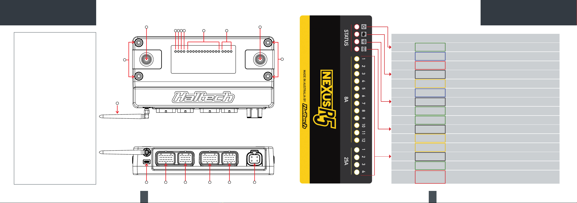
8A High Current Outputs (8A HCO)
The NEXUS R5 features 12 high side outputs which
are capable of driving 8A to 12V.
Each output has a software programmable fuse
current.
Once the electronic fuse blows the output turns
off for a software programmable delay duration,
before reactivating the output.
Use the software to define the maximum number
of retries before the output is deactivated untilthe
next ECU reboot. The ECU LEDs display the output
state.
8A HCOs are PWM capable and can be used to
power CAN devices or solenoids.
They can also control automatic transmission
shift solenoids, water pumps, some nitrous and
transbrake solenoids etc.
Specs:
• Automatic overcurrent protection
• Flyback protected
• 0 to 30V voltage feedback
• High side current feedback
• 100Hz max switching speed
• Capable of 0-100% duty cycle
25A High Current Outputs
The NEXUS R5 features four high/low outputs
capable of sinking 25A to ground and driving
25A to 12V. Each output has a programmable
fuse current, slow-start current and duration.
Once the electronic fuse blows the output turns
off for a pre-programmed delay duration before
reactivating the output. Use the NSP software to
define the maximum number of retries before the
output is deactivated until the next ECU reboot.
The ECU LEDs display the output state.
25A HCOs are PWM capable and can be used
for ignition power and injector power as well
as to PWM thermofans and fuel pumps, control
transbrake solenoids, nitrous solenoids etc.
Specs:
• Automatic overcurrent protection
• Flyback protected
• -30 to 30V voltage feedback
• High side current feedback
• 1kHz max switching speed
• Capable of 0-100% duty cycle
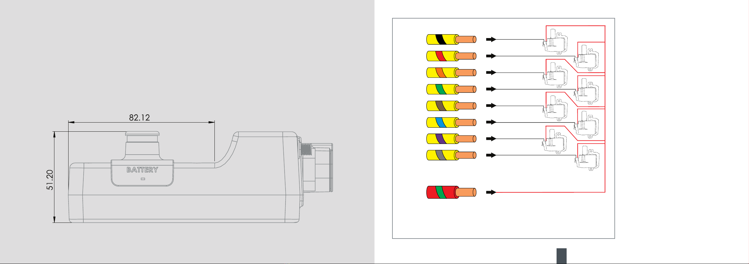
NEXUS R5 WIRING
8A HCO
TO GROUND
25A HCO
TO GROUND
THERMOFA N
Example Wiring Connections
Example Wiring Connections
Crank (Trigger) and Cam (Home) Inputs
The crank and cam position sensors are required
so that the ECU has the necessary information
available to determine engine speed and position
at any point in time.
Generally two sensors are required - a cam
position and crank position, however many
engines will have just a cam position sensor that
is capable of giving the ECU enough information to
run the engine correctly.
Vehicles that have a crank position sensor only
are not capable of determining the difference
between compression stroke and exhaust stroke
and therefore are not suitable for sequential fire
applications.
In this case a cam position sensor may need to be
added.
It is recommended that four-core or twin-core
shielded cable is used for crank and cam position
sensors. Shields must be terminated to battery
ground at one end only.
Specs:
• -5V to 5V input
• 1 million samples per second
• Selectable 1k2 or 440R pull-up to 5V
• Selectable ground reference (full differential
standard mode)
• -75 to 75V indefinite withstand
• 48kHz max signal frequency
There are two common types of crank/cam sensor
signals:
• Hall effect/optical signal
(0-5V digital square wave signal)
Hall effect sensors usually have 3 wires; a power
supply (5V, 8V or 12V), a ground and a signal
out wire. The power supply can be taken from
the Sensor +5V pin, sensor +8V pin or a HCO as
required.
• Reluctor signal (analog style signal)
This type of sensor will generally only have two
wires, signal positive (+) and signal negative ( - )
Sensors with a +5V supply do not require the pull-
up resistor be enabled, for example, rotary trim
modules.
Any sensor +5V pin can be used with any signal
ground pin for sensors.
Xindicates not connected
Please isolate and insulate
to avoid damage to ECU
Xindicates not connected
Please isolate and insulate
to avoid damage to ECU
Hall Eect Sensor
X
o
-
+
+12V
Signal Ground
Crank (Trigger) (+)
Crank (Trigger) (-)
Reluctor Sensor
X
-
+
X
+12V
Signal Ground
Crank (Trigger) (+)
Crank (Trigger) (-)
Example Wiring Connections