Progressive Dynamics PD2020 User manual

-1-
ELECTRONIC MARINE CONVERTER/CHARGER
Owners Manual
Models PD2020, PD2030, PD2040, PD2050, PD2060, PD2080
Thank you for purchasing the INTELI-POWER MARINE converter/charger. The
INTELI-POWER MARINE converter from Progressive Dynamics Inc. has been
designed and manufactured to meet the harsh environmental, mechanical and electrical
conditions that exist in the marine industry. The INTELI-POWER MARINE converter
incorporates our Patented Tri-Power circuitry and modern Microcontroller technology to
provide a Total Charge Management System for recharging and maintaining marine
batteries by providing 3 modes of operation, Normal, Boost, Trickle.
Progressive Dynamics Inc
507 Industrial Rd.
Marshall, MI 49068
(269) 781-4241
Fax (269) 781-7802
www.progressivedyn.com
-2-
Table Of Contents
IMPORTANT SAFETY INSTRUCTIONS ............................... -3-
PERSONAL PRECAUTIONS .......................................... -3-
LOCATING THE INTELI-POWER MARINE CONVERTER/CHARGER ..... -4-
DC CONNECTION PRECAUTIONS ................................... -5-
INSTALLING THE INTELI-POWER MARINE CONVERTER ............. -5-
OPERATING THE INTELI-POWER MARINE CONVERTER/CHARGER .... -10-
MAINTAINING THE INTELI-POWER MARINE CONVERTER/CHARGER
.......................................................... -11-
TROUBLE SHOOTING GUIDE ...................................... -11-
SAMPLE WIRING DIAGRAMS FOR SERIES/PARALLEL CONNECTIONS
.......................................................... -12-
SPECIFICATIONS ................................................. -14-
MARINE BATTERY CHARGER LIMITED WARRANTY ................ -16-

-3-
1. IMPORTANT SAFETY INSTRUCTIONS
1.1 SAVE THESE INSTRUCTIONS - This manual contains important
safety and operating instructions for the INTELI-POWER MARINE
series of electronic converter/chargers.
1.2 CAUTION - To reduce risk of injury, charge only lead-acid type
rechargeable batteries. Other types of batteries may burst causing
personal injury and damage.
1.3 Do not expose converter to rain, snow or excessive moisture .
1.4 Use of attachments not recommended or sold by Progressive
Dynamics Inc. may result in a risk of fire, electric shock, or injury to
persons.
1.5 Do not disassemble INTELI-POWER MARINE converter. Return it
to Progressive Dynamics Inc. when service or repair is required.
Incorrect reassembly may result in a risk of electric shock or fire.
1.6 To reduce risk of electric shock, disconnect A.C. power from the
INTELI-POWER MARINE converter before attempting any
maintenance or cleaning. Turning off controls will not reduce this
risk.
WARNING - RISK OF EXPLOSIVE GASES.
WORKING IN THE VICINITY OF A LEAD-ACID BATTERY IS DANGEROUS.
BATTERIES GENERATE EXPLOSIVE GASES DURING NORMAL BATTERY
OPERATION. FOR THIS REASON, IT IS OF UTMOST IMPORTANCE THAT
EACH TIME BEFORE SERVICING EQUIPMENT IN THE VICINITY OF THE
BATTERY, YOU READ THIS MANUAL AND FOLLOW THE INSTRUCTIONS
EXACTLY.
To reduce risk of battery explosion, follow these instructions and those published by
battery manufacturer and manufacturer of any equipment you intend to use in
vicinity of battery. Review any cautionary markings on these products and on
engine.
2. PERSONAL PRECAUTIONS
2.1 Someone should be within range of your voice or close enough to
come to your aid when you work near a lead-acid battery.
2.2 Have plenty of fresh water and soap nearby in case battery acid
contacts skin, clothing, or eyes.
2.3 Wear complete eye protection and clothing protection. Avoid
-4-
touching eyes while working near battery.
2.4 If battery acid contacts skin or clothing, wash immediately with soap
and water. If acid enters eye, immediately flood eye with running
cold water for at least 10 minutes and get medical attention
immediately.
2.5 NEVER smoke or allow a spark or flame in vicinity of battery or
engine.
2.6 Be extra cautious to reduce risk of dropping a metal tool onto battery.
It might spark or short-circuit battery or other electrical part that may
cause explosion.
2.7 Remove personal metal items such as rings, bracelets, necklaces, and
watches when working with a lead-acid battery. A lead-acid battery
can produce a short-circuit current high enough to weld a ring or the
like to metal, causing a severe burn.
2.8 NEVER charge a frozen battery.
2.9 If necessary to remove battery from vessel, always remove grounded
terminal from battery first. Make sure all accessories in the vessels
are off, so as not to cause an fire.
2.10 Be sure area around battery is well ventilated.
2.11 Clean battery terminals. Be careful to keep corrosion from coming in
contact with eyes.
2.12 Study all battery manufacturer's specific precautions such as
removing or not removing cell caps while charging and
recommended rates of charge.
2.13 Add distilled water in each cell until battery acid reaches level
specified by battery manufacturer. This helps purge excessive gas
from cells. Do not overfill. For a battery without cell caps, carefully
follow manufacturer's recharging instructions.
3. LOCATING THE INTELI-POWER MARINE CONVERTER/CHARGER
3.1 Locate the converter/charger in a well ventilated compartment.
-5-
3.2 Never place the converter/charger directly above the battery; gases
from battery will corrode and damage the converter/charger.
3.3 Never allow battery acid to drip on converter/charger when reading
specific gravity or filling battery.
3.4 Do not operate converter/charger in a closed-in area or restrict
ventilation in any way.
4. DC CONNECTION PRECAUTIONS
4.1 Connect and disconnect DC output connections only after opening
AC disconnect.
4.2 EXTERNAL CONNECTIONS TO CONVERTER SHALL
COMPLY WITH THE UNITED STATES COAST GUARD
ELECTRICAL REGULATIONS (33CFR183, SUB PART I).
4.3 GROUNDING INSTRUCTIONS - The INTELI-POWER
MARINE converter should be connected to a grounded, metal,
permanent wiring system. An equipment-grounding conductor should
be run with the circuit wiring and connected thru the charger housing
grommet to the equipment grounding (GND) terminal. Connections
to the converter should comply with all local codes and ordinances.
5. INSTALLING THE INTELI-POWER MARINE CONVERTER
! DANGER !
Before working on any electrical equipment, first determine
that there is no live power! Double check power connections, as
well as battery terminations.
5.1 MOUNTING LOCATION
Mount the INTELI-POWER MARINE converter vertically flush on
a bulkhead in a protected area away from rain or spray. Mount as
close to the batteries as possible. Ensure that there is six inches of
unobstructed area on all sides of the charger for air circulation and
cooling. See section 3 for precautions.
5.2 MOUNTING HARDWARE
Marine equipment is exposed to severe mechanical vibration and
shock, the screws or bolts used to mount the charger must be 3/16"
diameter, backed with a flat washer. A lock washer should be used to
prevent loosening of the connections due to vibration.
-6-
Figure 1
Figure 1
S
E R I E S
PD
Input:
Outputs: Volts: Amps:
CellType: Number ofCells:
Volts:105-135 VAC Hz: 50/60 Watts: 1000
3 13.6VDC 60 Total
Lead Acid 6
U.S.Patent No. 5,600,550 & 5,687, 066
Other P at ent s P end i ng
109734RA
Manufact ur ed b y
Pro
g
ressive D
y
namic s, Inc.
Marshall,MI 49068-1796
CAUTION:
Toreduce therisk of electricshock - Do not
exposeto rainor spray
CAUTION:
Toprevent fir e, donot c over orobst ruct
ventilat ion openings. Do not mount in zer o clearance
compartment. Overheat ing may result. Provided wit h
integral p rotection against overload s.
M
A
R
I
N
E
L
I
S
T
E
D
85JL
POWER
CONVERTER
CONTINUOUS DUTY, IGNITION PROT ECTED
On Boost
FastFlash FullCharge
Slow Flash Low Charge
Blink Storage
Off Dead B attery
Remove Screws for Access
ReplaceR everseBattery Protection Fuse(s) with
Same Typeand Rating: 30 AMP ATCStyle
TorqueOutput Terminals to: 50Inch Pounds Max.
TorqueInput Terminalsto 9 Inch Pounds Max.
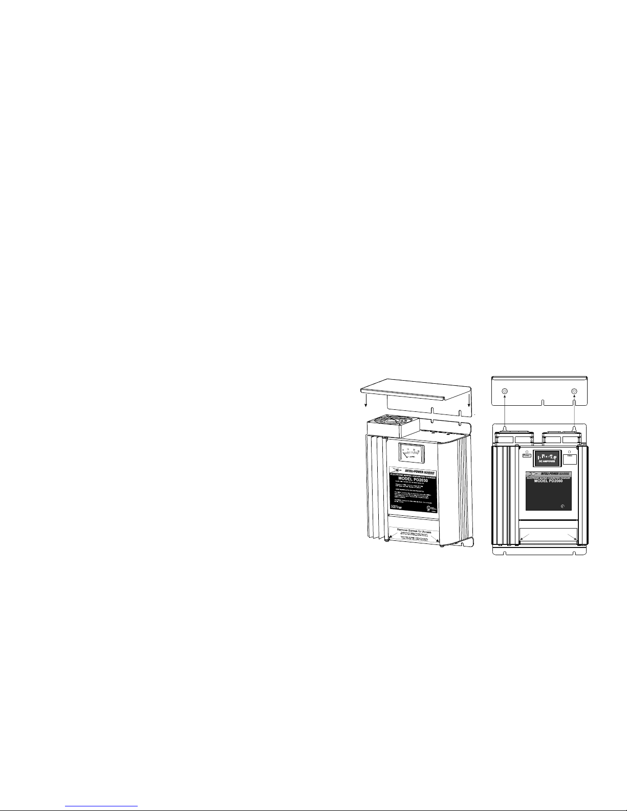
5.3 MOUNTING THE CONVERTER
Hold the converter/charger in place, mark all mounting hole
positions, remove the converter/charger and drill the holes.
Depending on the model converter, Install the mounting hardware on
one side of the charger into the drilled holes, Leave these loose at this
time. Align the mounting holes on the converter/charger with the
hardware installed in the drilled holes, align and install the remaining
hardware and firmly tighten all mounting hardware. For models with
2 fans or key hole slots in the base. Mark and drill mounting holes as
above. If using the drip shield, attach the drip shield leaving the
screws loose. Position the keyholes over the screws holding the drip
shield and slide the unit in place. Install the rest of the mounting
hardware and firmly tighten.
5.4 DRIP SHIELD
To install the drip shield leave the upper mounting screws loose,
slide the shield behind the base of the converter/charger. Align the
slots in the shield with the mounting hardware installed above and
firmly tighten all mounting hardware.
5.5 ELECTRICAL HARDWARE

-7-
This equipment is designed for hard-wiring in a permanent
application. Appropriate marine electrical installation hardware
should be used.
5.6 CHOOSING WIRE GAUGE
Connections to the INTELI-POWER MARINE CONVERTER shall
comply with U.S. Coast Guard Electrical Regulations (33CFR183
subpart I)
5.7 AC CONNECTIONS
After the appropriate wire gauges and lengths have been determined,
make connections to the AC input terminal block (see Figure 2). To
make connections to the terminal block, remove the cover retaining
screws and open the access panel. Feed the AC wiring through the
access hole near the AC terminal block. The terminals are labeled
for proper AC connections, The White wire should be connected to
the terminal marked NEU, the Black wire to the terminal marked
HOT, and the Green wire should be connected to the terminal
marked GND.
5.8 DC CONNECTIONS
After the appropriate wire gauges and lengths have been determined,
make connections to the DC output terminal block (see Figure 2).
Feed the DC wiring through the access hole near the DC outputs.
The terminals are labeled for proper DC connections, the INTELI-
POWER MARINE converter has three positive (+) terminals for up
to three battery banks. One common negative (-) terminal is
provided for connection to all battery banks.
5.9 INSTALLING EXTERNAL FUSE(S) (not supplied)
An external fuse or circuit breaker (not provided) must be installed
within 72 inches of the battery on each positive (+) DC output wire
that is connected to a battery bank. (Figure 2)
5.10 FINAL WIRING CHECK
Make sure all electrical connections have been properly made to each
battery bank and at the INTELI-POWER MARINE converter. Also
check that all wiring is properly dressed with no exposed, bare wires.
Close the access door and secure with the screws removed in sections
5.7.
DANGER
Under no circumstances should the INTELI-POWER MARINE
CONVERTER/CHARGER be operated with the access cover removed.
-8-
5.11 APPLYING POWER
Apply shore power to the unit and turn on the AC power source
circuit breaker. Check the meter mounted on the front of the
INTELI-POWER MARINE converter for movement. A large
movement in a clockwise direction indicates the batteries are in need
of a charge (there should be a slight movement even if the batteries
are charged). If a counter-clockwise movement occurs, turn off
power immediately and refer to the trouble shooting chart. If the
INTELI-POWER MARINE converter does not charge batteries or
perform as above refer to the trouble shooting chart for more
information.

-9-
Figure 2
Notes:
Note 1: AC stranded wire (see Table 1)
(AC connections may differ on
actual units).
Note 2: DC stranded wire (see Table 2)
Note 3: External fuse/circuit breaker.
(see Paragraph 6.9 and Coast
GuardReg. 33CDFR183
subpart I.)
Note 4: Reverse Battery Protection
fuse(s). (Will only blow if
battery is attached to
converter in reverse)
PD2020 & PD2030 are
supplied with one 30 AMP
Automotive type (ATC) fuse.
PD2040, PD2050 & PD2060
are supplied with two 30 AMP
Automotive type (ATC) fuses.
PD2080 is supplied with
Three 30 AMP Automotive
Type (ATC) Fuses.
-10-
6. OPERATING THE INTELI-POWER MARINE CONVERTER/CHARGER
6.1 Always follow all precautions in the IMPORTANT SAFETY
INSTRUCTIONS in Part 1 of this manual.
6.2 PROPER OPERATION
When properly installed and connected, the INTELI-POWER
MARINE converter/charger will monitor the battery condition then
automatically select one of it’s three operating modes to provide the
correct charging level.
NORMAL MODE:
In the normal mode the output voltage is set at 13.6 volts DC. This
voltage provides good charging rates and low water usage.
BOOST MODE:
If the INTELI-POWER MARINE converter/charger senses the
battery voltage has dropped below a preset level, the system
automatically switches into the Boost Mode. In this mode the charge
voltage is increased to 14.4 volts for a period of approximately 4
hours.
TRICKLE MODE:
When the INTELI-POWER MARINE converter/charger senses that
there has been no significant battery usage for a period of
approximately 30 hours the charge voltage is automatically reduced
to 13.2 volts DC for minimal water usage until the unit senses usage
of the electrical system.
EQUALIZATION MODE:
When the charger is in the Storage Mode, the microprocessor
automatically equalizes the battery by increasing the charging
voltage to 14.4 volts for 15 minutes every 21 hours. This causes the
battery to gas for a short time and re-mixes the electrolyte to prevent
the buildup of sulfation on the battery plates.
6.3 INTERNAL FUSE REPLACEMENT
The INTELI-POWER MARINE converter/charger has one, two or
three user replaceable fuses located behind the access panel. The
fuse(s) will blow ONLY in the event of a battery being connected to
the unit in reverse. To change the fuse(s), remove the screws
securing the access panel and open the panel. The fuse(s) are located
directly above the negative battery terminal inside the unit. Replace
the fuse(s) with only the same type and rating, 30 Amp ATC fuse(s).
-11-
7. MAINTAINING THE INTELI-POWER MARINE
CONVERTER/CHARGER
7.1 No adjustments or maintenance is required for the INTELI-POWER
MARINE converter other than periodically checking all electrical
connections for tightness by a qualified service person.
CAUTION
Check battery water level frequently, especially if boat is
at dock for extended periods of time. Low water levels
will damage batteries!
TROUBLESHOOTING THE INTELI-POWER MARINE CONVERTER/CHARGER
TROUBLE SHOOTING GUIDE
PROBLEM POSSIBLE CAUSES ACTION
1. No Output 120 VAC supply not
connected
Connect power supply
Check AC distribution panel for
proper operation
Internal Fuse(s) Blown Check for Reverse Polarity
Replace Fuse(s) with same type
and rating
Short Circuit Trace Vessel Circuits for possible
fault
Unit has shutdown due
to overheating
Check air flow
Allow unit to cool
Unit has shutdown due
to over voltage
Check input voltage
Converter will shut down if the
input voltage exceeds 132 Volts
Correct Input Voltage
2. Internal Fuse(s)
Blown
Reverse Battery Hook
Up
Correct Hook up and replace
Fuse(s) with same type and rating
3. Converter
cycles on & off
Compartment gets too
hot
Check air flow to the converter
Improve Ventilation to the
compartment
4. Low Output Excessive Load for
Converter
Reduce load requirements or
Install Larger Converter
Input Voltage not
between 105-130 VAC
Correct input supply voltage
Bad Battery Cell(s) Replace Battery
-12-
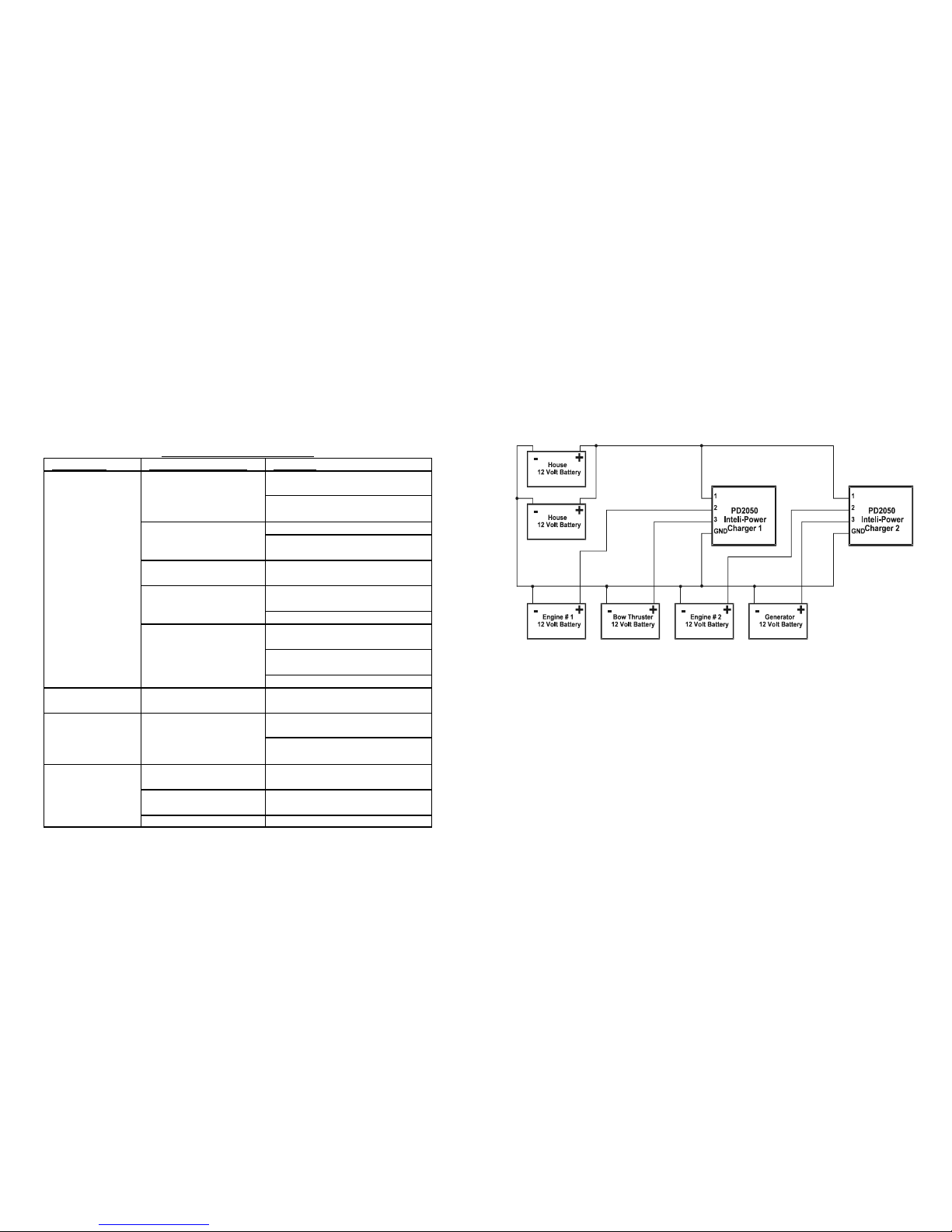
SAMPLE WIRING DIAGRAMS FOR SERIES/PARALLEL CONNECTIONS.
The Inteli-Power chargers can be wired in series to provide a 24 volt charging system.
They can also be wired in parallel to provide additional charge current.
Parallel Connection:
Wiring the Inteli-power chargers as shown below will provide additional charging
current to the 12 volt house battery system and eliminates the need to install additional
chargers for the engine, generator and the 12 volt bow thruster batteries.
The Parallel system shown above using PD2050 Chargers can provide a maximum of
100 amps to recharge the house battery system. It can also provide up to 50 amps to
charge the engine, bow thruster or generator batteries if the house batteries are fully
charged.
-13-
Inteli-Power
Charger 1
Inteli-Power
Charger 2
1
1
2
2
3
3
GND
GND
Engine # 2
12 Volt Battery
+-
House
12 Volt Battery
+-
Bow Thruster
12 Volt Battery
-+
Bow Thruster
12 Volt Battery
-+
Engine # 1
12 Volt Battery
+-
Engine # 1
12 Volt Battery
-+
Engine # 2
12 Volt Battery
-+
Output Voltage = 12 Volts
Output Voltage = 24 Volts
Series Connection:
Wiring the Intelipower chargers as shown below will provide a combination of 12
and 24 volt charging system. This can eliminate the need to install expensive battery
equalizers and additional chargers for the 12 volt house and 24 volt bow thruster
batteries.
The Series system shown above will provide 24 volt charging for the bow thruster and
engine batteries while supplying 12 volt charging for the house battery.
-14-
Do not replace the converter unless the following checks have been performed:
1. Loosen the screw on all the positive terminals and disconnect the positive wires.
Read the converter output voltage using a DC voltmeter. If the voltage is above 13
volts, the converter is working properly.
2. If the converter output is zero volts, use an AC voltmeter to check for proper voltage
on the 120 VAC power source. This voltage should be between 104 and 130 volts.
3. Check the fuse(s) located next to the output terminal block inside the converter. The
fuse(s) will only blow if the battery or DC output leads were connected in reverse,
even for a moment. Replace the fuse(s) and repeat step 1.
SPECIFICATIONS
PD2020
Input: 105-130 VAC 50/60 Hz
350 Watts
Output: 13.6 VDC, 20 Amps
Dimensions: L= 10.2" W= 7.8" H=4.2"
Weight: 6lbs
PD2030
Input: 105-130 VAC 50/60 Hz
550 Watts
Output: 13.6 VDC, 30 Amps
Dimensions: L= 10.2" W= 7.8" H= 4.2"
Weight: 6.25lbs
PD2060
Input: 105-130 VAC 50/60 Hz
1000 Watts
Output: 13.6 VDC, 60 Amps
Dimensions: L= 10.2" W= 7.8" H= 4.2"
Weight: 6.5lbs
PD2040
Input: 105-130 VAC 50/60 Hz
650 Watts
Output: 13.6 VDC, 40 Amps
Dimensions: L= 10.2" W= 7.8" H= 4.2"
Weight: 6.25lbs
PD2050
Input: 105-130 VAC 50/60 Hz
900 Watts
Output: 13.6 VDC, 50 Amps
Dimensions: L= 10.2" W= 7.8" H= 4.2"
Weight: 6.5lbs
PD2080
Input: 105-130 VAC 50/60 Hz
1300 Watts
Output: 13.6 VDC, 80 Amps
Dimensions: L= 10.2" W= 7.8" H= 4.2"
Weight: 8.8lbs
©2002 Progressive Dynamics, Inc. All rights reserved. Quiet Sensor is a registered
trademark of Progressive Dynamics, Inc.
PATENT NUMBERS 5,600,550, 5,687,066, 5982,643 and 6,184,649.

-15-
Notes:
Model #
Serial #
-16-
PROGRESSIVE DYNAMICS, INC.
MARINE BATTERY CHARGER LIMITED WARRANTY
I. LIMITED WARRANTY: Progressive Dynamics, Inc. warrants its battery chargers to be free from
defects in material or workmanship under normal use and service, and limits the remedies to repair or
replacement.
II. DURATION: This warranty shall extend for a period of two years from the original date of
manufacture and is valid only within the continental limits of the United States and Canada.
III. WARRANTY EXCLUSIONS: This warranty specifically does not apply to:
A. Any battery charger which has been repaired or altered in any way by an
unauthorized person or service station;
B. Damage caused by excessive input voltage, misuse, negligence, or accident,
or an external force;
C. Any battery charger installed in a craft used for commercial purposes;
D. Any battery charger which has been connected, installed, or adjusted, or used
other than in accordance with the instructions furnished, or has had the serial
number altered, defaced, or removed;
E. Cost of all services performed in removing and reinstalling the battery
charger; and
F. ANY LOST PROFITS, LOST SAVINGS, LOSS OF USE OF ENJOYMENT
OR OTHER INCIDENTAL DAMAGES ARISING OUT OF THE USE OF,
OR INABILITY TO USE, THE PRODUCT. THIS INCLUDES DAMAGES
TO PROPERTY AND—TO THE EXTENT PERMITTED BY
LAW—DAMAGES FOR PERSONAL INJURY. THIS WARRANTY IS
IN LIEU OF ALL OTHER WARRANTIES, INCLUDING IMPLIED
WARRANTIES OF MERCHANTABILITY AND FITNESS FOR A
PARTICULAR PURPOSE.
IV. CLAIM PROCEDURE: Upon discovery of any defect, Progressive Dynamics, Inc. shall be supplied
the following information by mail, telephone, or fax at the address listed below:
A. Name and address of the claimant;
B. Name and model of the battery charger;
C. Name, year, and model of the craft in which the charger was installed;
D. Date of purchase; and
E. Complete description of the claimed defect.
Upon determination that a warranty claim exists (a defect in material or workmanship occurring under
normal use and service), the battery charger shall be shipped postage prepaid to Progressive Dynamics,
Inc. together with proof of purchase. The battery charger will be repaired or replaced and returned
postage prepaid.
Progressive Dynamics, Inc.
507 Industrial Road
Marshall, Michigan 49068
Phone: 269-781-4241 Fax: 269-781-7802
www.progressivedyn.com
109387 Rev. F
This manual suits for next models
5
Table of contents


