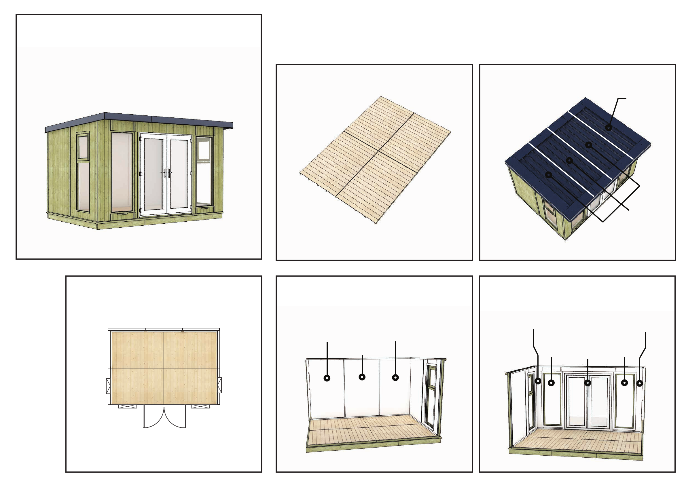
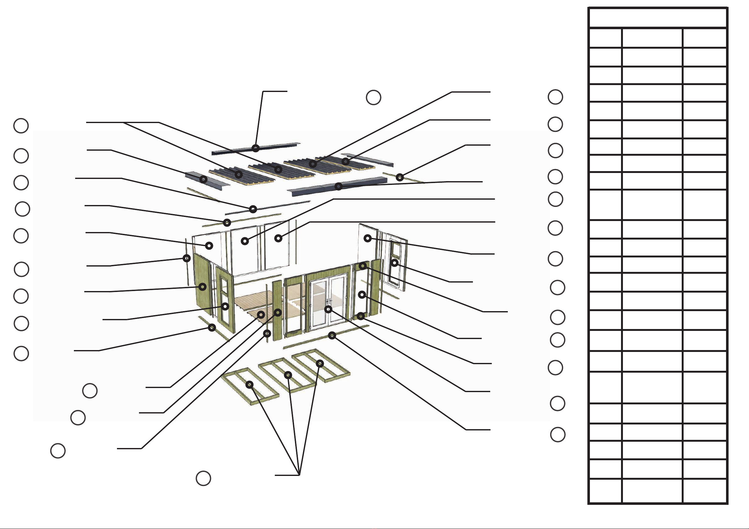
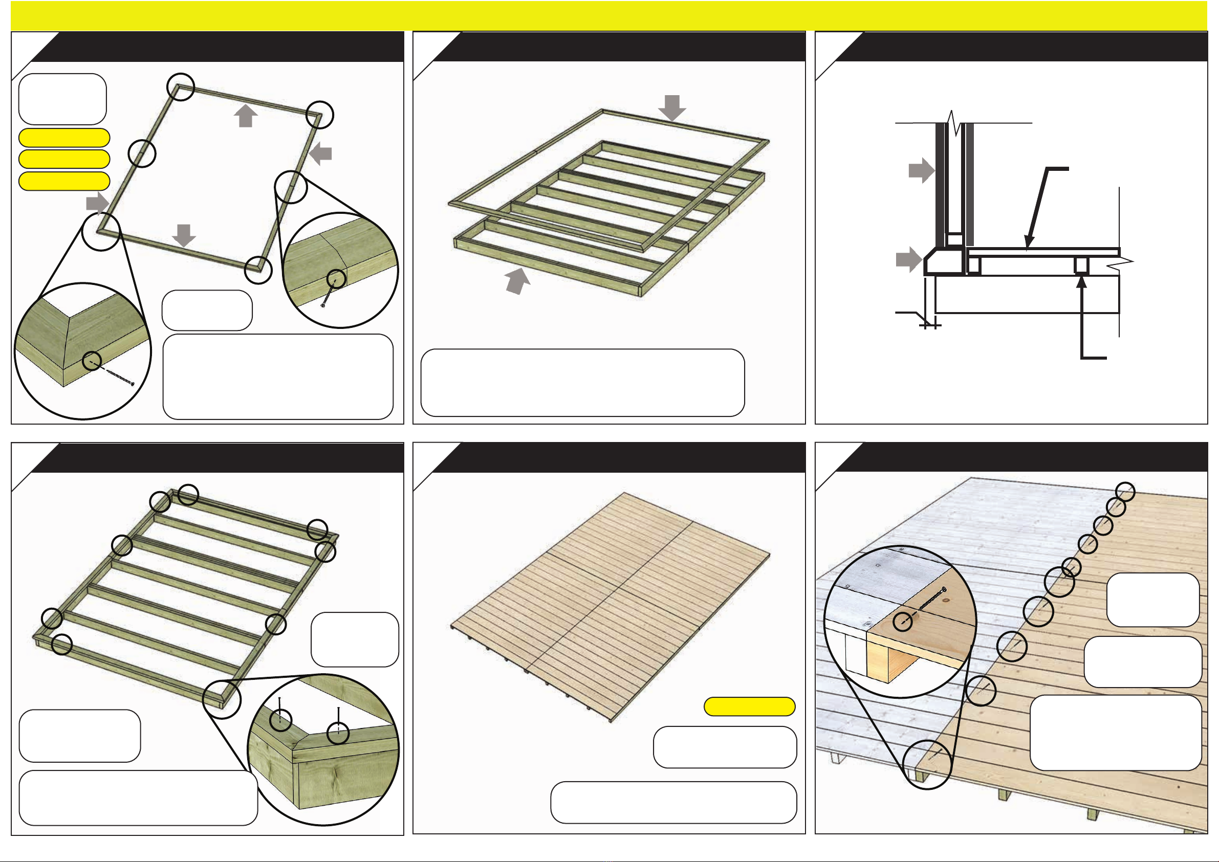
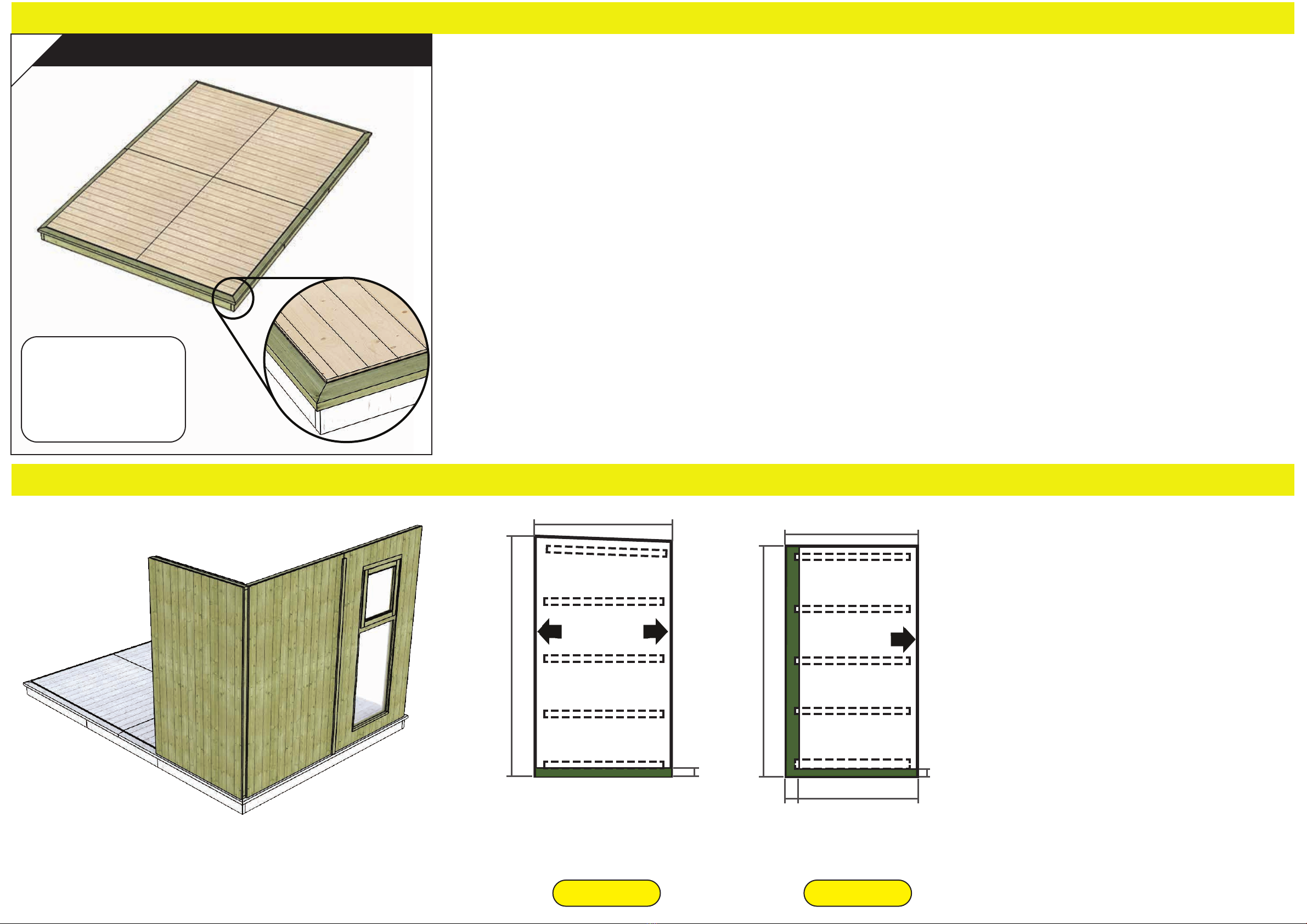
Project Timber Evolution My Den 12x8 Instruction Manual


Other Project Timber Garden House manuals

Project Timber
Project Timber Corner Shed Windowless Instruction Manual

Project Timber
Project Timber Evolution My Den 8x6 Instruction Manual

Project Timber
Project Timber Evolution My Den 16x8 Instruction Manual

Project Timber
Project Timber Cannes Summerhouse Instruction Manual

Project Timber
Project Timber 20x6 Hobbyist Windowed Pent Shed Instruction Manual

Project Timber
Project Timber My Den Metal Roof Instruction Manual

Project Timber
Project Timber Cannes Summerhouse 12x6 Instruction Manual

Project Timber
Project Timber Corner Shed Instruction Manual

Project Timber
Project Timber Evolution My Den Instruction Manual

Project Timber
Project Timber Evolution My Den Instruction Manual

Popular Garden House manuals by other brands


OLT
OLT SunShed Garden Shed SSGS1212-AK-METAL Assembly manual

STILLA
STILLA Oxford 6x9 S3021 Assembly instructions

Reynolds Building Systems
Reynolds Building Systems West Virginia 16'x32' Assembly Book

GARDIVAL
GARDIVAL VERSAILLES 250 manual

Luoman
Luoman LILLEVILLA Tyrni Assembly and Maintenance

Luoman
Luoman Lillevilla 321 Assembly and Maintenance


