manuals.online logo
Brands
  1. Home
  2. •
  3. Brands
  4. •
  5. Project Timber
  6. •
  7. Garden House
  8. •
  9. Project Timber Evolution My Den 8x6 Instruction Manual

Project Timber Evolution My Den 8x6 Instruction Manual

8x6
Evolution My Den
Building Instructions
Cover Size:
Please read the instruction carefully
and retain for future reference
For Queries and Help please contact 01777 802300
Please note that all images are for illustration purpose only.
V1.4 20.04.22 INS0140
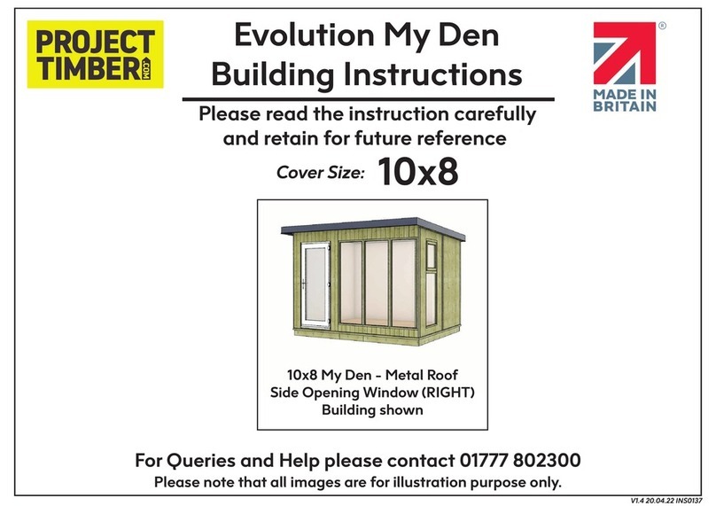
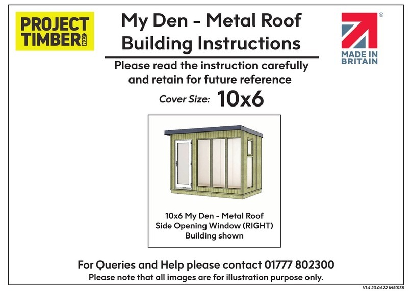
8x6 My Den - Metal Roof
Side Opening Window (RIGHT)
Building shown
8x6 Evolution My Den
Metal Roof
Side Window Opening (RIGHT)
shown Floor Assembly
2348mm x 1217mm (1)
585mm x 2348mm (1)
Metal Roof
position 515mm
1000mm
1220mm 1220mm
Back Panels
position
Front Panels
position
610mm
Single
Door
Panel
610mm
1220mm1220mm
585mm
(LOW)
585mm
(LOW)
1220mm
(HIGH)
610mm
610mm
Side
Window
Opening
(RIGHT)
Door
Position
(LEFT)
8x6 Floor Plan
Front of Building
Door Position (LEFT)
Door Position (RIGHT)
Door and Front Windows position options
Single Door Panel
(LEFT)
Glazing Units
(610mm)
Single Door Panel
(RIGHT)
Glazing Units
(610mm)
To p
Panel
Bottom
Panel
To p
Panel
Bottom
Panel
IMPORTANT: Always check the internal lining corner gap of the panels
2135mm
1220mm
Side Window
Opening Panel
(LEFT)
Diagram
ID: PT25521
1220mm1220mm
585mm
(LOW)
585mm
(LOW)
1220mm
(HIGH)
610mm
610mm
Side
Window
Opening
position
(LEFT)
Door
Position
RIGHT
Floor Plan
Front of Building
Front
Left Side
Side Opening Window (LEFT)
position option
Drip Edge
Flashing
Barge Board
Flashing
Gable Panel
(LEFT - Low)
Gable Panel
(LEFT - High)
Back Corner
Trims
Front Corner
Trims
Base Module
I - LEFT
Base Module
I - RIGHT
11mm Floor
Panels
11mm Floor
Panels
6ft Gable
Plinth
8ft Plinth
Top Plain
Panel
Bottom Plain
Panel
Single Door
Panel / UPVC
Single Door
Gable Panel (High)
with Window Opening
Gable Panel
(Right - Low)
(LEFT) Back Panel
(1220mm WIDTH)
(RIGHT) Back Panel
(1220mm WIDTH)
Window Panels
(610mm WIDTH)
Roof Section
1000mm Width
Roof Section
515mm Width
Roof Section
1000mm Width
Rear Frame
Standoff
Gable Frame
Standoff
8ft Front Monopitch
Ridge Flashing
8ft Back Water
Deflector Flashing
Building Parts: 8x6 Evolution My Den
Metal Roof Building Parts
Part ID
PT25541
PT25542
PT25531
PT25532
PT20323
PT25548
21150
21159
21166
21169
21173
21178
15906
18685
PT18490
PT25522
PT25534
PT20330
19503
PT25393
PT18173
PT18181
PT21074
Wood Kit
1
1
1
1
1
1
2
1
1
1
1
2
2
2
2
1
1
1
1
2
1
1
QTYNo.
1
2
3
4
5
6
7
8
9
10
11
12
13
14
15
16
17
18
19
20
21
22
1
3
4
5
6
7
6
8
9
10
11
12
13
14 15
16
17
18
19 19
21
20
22
2
22
22
22
Base Module Woodkits
1220mm 1220mm
Base Module (For each end of the assebled base)
Gable Bearers
Fixing Kit
1. Base Module I - 1893mm x 2440mm (2)
2. Gable Bearers - 38mm x 1817mm (2)
Parts List required:
ID: PT25393
ID: PT25397
Base Module fixing
Side
Front
Base Module I x 2
1220mm 1220mm
I
I
1
Side
1220mm
Module
Pilot drill
holes before
fixing
Base Module fixing
100mm
Screws
ID: PT25393
2
Side Front
Back
Alternate sides
to screw together
Pilot drill holes
before fixing
Base Module fixing
70mm
Screws
3
Base Module Stages
Side
Front
Gable Bearers are fitted on each side of
fully assembled base. This gives extra
room for the floor sections. (see diagram)
Pilot drill holes
before fixing
Base Module fixing
70mm
Screws
Floor Joist
Floor Boards
Side of
Base Module
Plinth
Gable
Bearer
Base Module Diagram
Side
Front
Back
Position the gable bearers each side to
the fully assembled base. Secure with
70mm screws
Base Module fixing
70mm
Screws
ID: PT23597
Check the base module can sit level to the
ground. Use spirit level when leveling all
corners of the base.
Base Module fixing
Side
Front
Base Module fixing
Side
Front
Side Front
Back
Ensure the ground must be flat and level,
before laying the base module assembly.
Base Module fixing
4
78 9
5 6
Floor Section Stages
Plinth
Base Module
Position the plinth into the top of
pre-assembled base module
Floor Stages
Floor Sections Diagram
Wall
Panel
Plinth
Gap
Base Module
Side View
Floor
Boards
Floor Joist
Side
Front
Back
Lay and fix the Plinth
lengths together at
the corner
Pilot drill holes
before fixing
Floor Stages
4 70mm
Screws
ID: 15906
ID: 18685
Fix the Floors together
Floor Stages
Side
Front
Back
11mm Floor
assembly shown
ID: PT18173
ID: PT18181
50mm
Screws
Floor Stages
Fix the Floors with
screws in angled
position
Back
Side
Pilot drill holes
before fixing
Fix and secure the
plinth and base
module together
Side
Front
Back
Floor Stages
Pilot drill holes
before fixing
70mm
Screws
10
13 14 15
11 12
Floor Section Stages
Wall Panels Section Stages
Panel Position Diagram
Front of Building
Rear
Side
(Left) Side
(Right)
Side
(LEFT)
Front
1. Door Panel - LEFT (1)
2. UPVC Single Door - LEFT (1)
3. Left Gable Panel - HIGH (1)
4. Left Gable Panel - LOW (1)
5. Gable Cloaking Strip (1)
60mmx16mmx2050mm
Parts List required:
16mm
2135mm
74mm1146mm
1220mm
Lining Flush
16mm
2135mm
21mm 1199mm
1220mm
Lining Flush
Door Panel
Diagram Left Gable Panel(HIGH)
Diagram
ID: PT20330 / 19503 ID: PT25534
Floor Stages
Side
Front
Back
Place the floor assembly
inside the plinth and
base module.
16
Wall Panels Section Stages
2 50mm
Screws
Front
Side
(LEFT)
Pilot drill holes
before fixing
*Check the Side Opening
Window (LEFT) position
option floor plan for
guidelines.
Position and fix
the plain gable
panel (Left)
Left Gable (High) Panel Stages
ID: PT25534 50mm
Screws
Front
Side
Front
Side
(LEFT)
Pilot drill holes
before fixing
Align and fix the door
section to the left gable
panel (high) and plinth
Left Gable and Door Panel (LEFT) Position
Front
Side
Lining
Flush
Lining
Flush
Left Gable (High) Panel Stages
Front
Side
(LEFT)
Align and fit the UPVC Door Cill
to the door panel (LEFT)
UPVC Door fixing
ID: 19503
80mm
Screws
Front
Fix and secure the UPVC
Door Cill to the door panel
UPVC Door fixing
ID: 19503
50mm
Screws
Side
Front
Pilot drill holes
before fixing
Fit the Plain Gable
Panel and Door
Panel in this position
Gable and Door Panel Position
17
20 21 22
18 19
Wall Panels Section Stages
80mm
Screws
Front
Fix and secure the UPVC Door
section to the door panel
UPVC Door fixing
ID: 19503
50mm
Screws
Side
(LEFT)
Pilot drill holes
before fixing
Cloaking Strip is used to fix
the panels together
Position and fix
the gable
cloaking strip
LEFT - Gable Cloaking Strip (CS)
ID: PT21074
Front
Side
(LEFT)
Position and fit the UPVC Door
section to the door panel (LEFT)
UPVC Door fixing
ID: 19503
50mm
Screws
Side
(LEFT)
Front
Pilot drill holes
before fixing
Position and fix the Side
Gable (Low) Panel
Left Gable (Low) Panel Stages
ID: PT25531
16mm
2094mm
585mm
Lining
Flush
Left Gable (Low) Panel Diagram
ID: PT25531
23
26 27
24 25
REAR - Wall Panels Section Stages
Panel Position Diagram
Front of Building
Rear
Side
(Left)
Side
(Right)
Side
(RIGHT) Rear
1. LEFT Back Panel
1220mm (1)
2. RIGHT Back Panel
1220mm (1)
3. Rear Cloaking Strip (1)
60mmx16mmx2012mm
Parts List required:
16mm
2055mm
74mm 1146mm
1220mm
Lining Flush
16mm
2055mm
74mm1146mm
1220mm
Lining Flush
LEFT Back Panel
(1220mm) Diagram
RIGHT Back Panel
(1220mm) Diagram
ID: PT25541 ID: PT25542
74mm
1220mm
Back Panel (LEFT)
1220mm
Back Panel (Right)
Back Panels Position
28
50mm
Screws
Back
Pilot drill holes
before fixing
Angle
screw
at top
Align and fix
the back plain
(LEFT) panel
Back Panel Stages
ID: PT25541
29
50mm
Screws
Back
Side
(RIGHT)
Pilot drill holes
before fixing
Position and fix the
Back Cloaking Strip (CS)
Gap for guttering
at top
REAR - Cloaking Strip (CS)
ID: PT21074
30
REAR - Wall Panels Section Stages
RIGHT - Gable Wall Panels Section Stages
Panel Position Diagram
Front of Building
Rear
Side
(Left)
Side
(Right)
Side
(RIGHT)
Back
Right Opening
Window (High)
Panel Right Gable
(Low) Panel
Cloaking Strip
1. Right Window Gable
Panel - HIGH (1)
2. Right Gable
Panel - LOW (1)
3. Gable Cloaking Strip (1)
60mmx16mmx2050mm
Parts List required:
16mm
2094mm
585mm
Lining
Flush
16mm
2135mm
1220mm
Lining Flush
Right Window Panel
(HIGH) Diagram
Right Gable Panel
(LOW) Diagram
ID: PT25532 ID: PT25522
Back
Position and fix the back panel
(RIGHT) and cloaking strip
Back Panel Stages
50mm
Screws
ID: PT25542
31
RIGHT - Gable Wall Panels Section Stages
Door on the Left Panel Stages
Panel Position Diagram
Front of Building
Rear
Side
(Left)
Side
(Right)
Side
(RIGHT)
Front
1. Window Glazing Unit (W610mm) - (2) [ID: PT18490]
2. Plain Panel TOP (W1220mm) - (1) [ID: PT20323]
3. Plain Panel BOTTOM (W1220mm) - (1) [ID: 25548]
Parts List required:
Door
(LEFT)
Back
Position and fix the back panel
(RIGHT) and cloaking strip
Back Panel Stages
50mm
Screws
ID: PT25542
32
50mm
Screws
Back
Side
(RIGHT)
Position and fix the side
Plain Gable Panel (right)
Pilot drill holes
before fixing
Right Gable (Low) Panel Stages
ID: PT25532
33
50mm
Screws
Side
(RIGHT)
Pilot drill holes
before fixing
Position and fix
the right gable
cloaking strip
RIGHT - Gable Cloaking Strip (CS)
ID: PT21074
34
Door on the Left Panel Stages
50mm
Screws
Front
Pilot drill holes
before fixing
Secure the Bottom Panel
Bottom Panel Stages
ID: PT20327
Front
Position and align
the Glazing Unit
Glazing Unit fixing
*Check the Front Window
Panels position option
(LEFT or RIGHT).
Front Slide and fit the Bottom
Panel (LEFT) to the
side of door section and
side gable panels.
Check the corner
gap of panel
Bottom Panel Stages
*Check the Door Panel
and Front Window
Panels position options
(LEFT or RIGHT).
ID: PT20327
70mm
Screws
Front
Pilot drill holes
before fixing
Glazing Unit fixing
S70
S70
S70
S70
ID: PT18490
70mm
Screws
Front Pilot drill holes
before fixing
Glazing Unit
fixing
Glazing Unit fixing
S70
S70
S70
S70
ID: PT18490
Front
Secure the
Glazing
Unit.
Use 70mm
Screws
through
the back
rebate
Pilot drill holes
before fixing
Glazing Unit fixing
S70 S70
S70
S70
ID: PT18490
35
38 39 40
36 37
50mm
Screws
Front
Pilot drill holes
before fixing
Fix and secure
the Top Panel
Top Panel Stages
ID: PT20323
70mm
Screws
Front
Pilot drill holes
before fixing
Top Panel fixing
Top Panel Stages
S70 S70
S70
S70
Front
Check the corner
gap of panel
Position the Top
Panel to the top
of glazing units
Top Panel Stages
BACK - Corner Trims (CT)
60mm x 16mm
x 2050mm
Corner Trim
80mm
Screws
Back
Side
Back
Side
ID: PT21074
Panel
Pins
40mm x 11mm
x 1740mm (1)
Window Frame Cloaking Strip (CS)
ID: PT21074
FRONT - Corner Trims (CT)
60mm x 16mm
x 2135mm
Corner Trim
80mm
Screws
Front
Side
Front
Side
ID: PT21074
41
44 45 46
42 43
50mm
Screws
Position and fix
the Gable Frames
44mm x 27mm
x 2050mm (2)
Side Back
SideFront
Pilot drill holes
before fixing
GABLE - Roof Stand-Off Frame (SOF)
ID: PT21074
50mm
Screws
Back
Position and fix the
Drip Edge Flashing
Drip Edge Flashing Stages
Pilot drill holes
before fixing
ID: 21173
50mm
Screws
Back
Position and fix
the Rear Frame.
44mm x 27mm
x 2475mm (1)
REAR - Roof Stand-Off Frame (SOF)
Pilot drill holes
before fixing
ID: PT21074
Drip Edge Flashing Length Size
Building size
8x6 L2530mm x 1
Drip Edge Flashing Lengths
Back View
Side
Back
Drip Edge
Flashing
Gable
Frame
Drip Edge Flashing position
47
50 51
48 49
Roof Section Stages
Floor Plan
Front of Building
Rear
Side
(Left)
Side
(Right)
Side
(RIGHT)
Front
1. Metal Roof Section L2285mm x W515mm - (1) [ID: 21159]
2. 115mm Metal Roof Screws
Parts List required:
515mm
Wide
Roof Section Stages
115mm Metal
Roof Screws
See
Cross-section
diagram
Screws must fix
throught the
top ridge
Position the shortest
width of roof section
and ensure to fit
underneath to the
wall panels. Secure
with metal screws.
* Use Step ladder when
fixing the roof sections,
2 people are required.
ID: 21159
52
Roof section
position
Only 1 screw is required
at the back to hold the
position of the roof
Back
Side
(RIGHT)
Side
(RIGHT)
Front
Roof Section Stages
53
Roof Section Stages
Roof sections
overhang
13mm at the
rear.
13mm
Rear
Side
(RIGHT)
54
Roof Section Stages
Roof Section Stages
Floor Plan
Front of Building
Rear
Side
(Left)
Side
(Right)
Side
(LEFT) Front
1. Metal Roof Section L2285mm x W1000mm - (2) [ID: PT21150]
2. 115mm Metal Roof Screws
Parts List required:
1m
Wide
1m
Wide
Metal
Roof
Wall
Panels
115mm Metal
Roof Screw
Ensure the 98mm metal roof screws
fix through to the wall panels
Metal Roof Cross-Section Diagram
55
Roof Section Stages
115mm Metal
Roof Screws
Ensure the 115mm metal roof screws is align
and fix through to the wall panels below.
ID: 21159
56
Roof Section Stages
115mm Metal
Roof Screws
57
Roof Section Stages
Roof Section Stages
1m
Wide
Repeat previous roof
section fixing stages
115mm Metal
Roof Screws
* Use Step ladder when
fixing the roof sections,
2 people are required.
ID: 21150
Roof section
position
Back
Side
(LEFT)
Side
(LEFT) Front
Roof Section Stages
Roof Section Stages
1m Wide
Position the 1m wide roof
section and slot it into the
first roof section. Fix in
place with metal
roof screws
Only 1 screw is required
to hold the back in place
in this stage
115mm Metal
Roof Screws
ID: 21150
Water Deflector Flashing Length Size
Building size
8x6 L2530mm x 1
Water Deflector Flashing Lengths
Back View
Barge Board Flashing Stages
Position the Barge Board
Flashing on both side of
roof sections. Fix the
flashing through the top
ridge of metal roof.
2292mm
ID: 21178
115mm Metal
Roof Screws
115mm Metal
Roof Screws
Back
Position and fix the
Water Deflector Flashing.
Fix the flashing through
the top ridge of metal
roof.
Water Deflector Flashing Stages
ID: 21169
The screws already in
the roof will need to
be removed before
the flashing fitted.
58
61 62 63
59 60
Roof Section Stages
25mm Metal
Roof Screws
Front
Position and fix the
Monopitch Ridge Flashing
to the front of roof sections.
These are the same lenghts
of water deflector flashing
Monopitch Ridge Flashing Stages
ID: 21166
Back Side
Side
Front
Barge Board Flashing Stages
UPVC Single Door Glazing Unit fixing
Gently position and
fit the door glazing
unit to the uPVC
door frame
ID: 25327
UPVC Single Door Glazing Unit fixing
UPVC Door
frame
Door
Glazing Unit
Position and sit the glazing unit to the bottom
rubber strip. Gently fit the glazing unit to
the door frame.
ID: 25327
Rubber
fitting strip
UPVC Single Door Glazing Unit fixing
Position the rubber
strip to the bottom
of the door frame
64
66 67 68
65

Other Project Timber Garden House manuals

Project Timber Corner Shed Instruction Manual

Project Timber

Project Timber Corner Shed Instruction Manual

Project Timber Evolution My Den Instruction Manual

Project Timber

Project Timber Evolution My Den Instruction Manual

Project Timber Corner Shed Windowless Instruction Manual

Project Timber

Project Timber Corner Shed Windowless Instruction Manual

Project Timber 20x6 Hobbyist Windowed Pent Shed Instruction Manual

Project Timber

Project Timber 20x6 Hobbyist Windowed Pent Shed Instruction Manual

Project Timber My Den Metal Roof Instruction Manual

Project Timber

Project Timber My Den Metal Roof Instruction Manual

Project Timber Evolution My Den 16x8 Instruction Manual

Project Timber

Project Timber Evolution My Den 16x8 Instruction Manual

Project Timber Cannes Summerhouse Instruction Manual

Project Timber

Project Timber Cannes Summerhouse Instruction Manual

Project Timber Evolution My Den Instruction Manual

Project Timber

Project Timber Evolution My Den Instruction Manual

Project Timber Hobbyist Instruction Manual

Project Timber

Project Timber Hobbyist Instruction Manual

Project Timber Evolution My Den 12x8 Instruction Manual

Project Timber

Project Timber Evolution My Den 12x8 Instruction Manual

Project Timber Cannes Summerhouse 12x6 Instruction Manual

Project Timber

Project Timber Cannes Summerhouse 12x6 Instruction Manual

Popular Garden House manuals by other brands
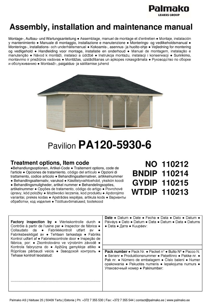
Lemeks Palmako EL18-4533-3 Assembly, installation and maintenance manual
Lemeks

Lemeks Palmako EL18-4533-3 Assembly, installation and maintenance manual

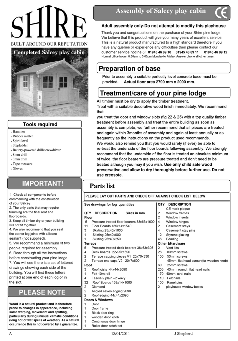
Shire Flat Pack Loft Assembly

Shire

Shire Flat Pack Loft Assembly

Weka 262.2121 ASSEMBLY, USER AND MAINTENANCE INSTRUCTIONS

Weka

Weka 262.2121 ASSEMBLY, USER AND MAINTENANCE INSTRUCTIONS

Dunster House BAT installation manual

Dunster House

Dunster House BAT installation manual

Palmako Lisa FR44-4735-2 installation manual

Palmako

Palmako Lisa FR44-4735-2 installation manual

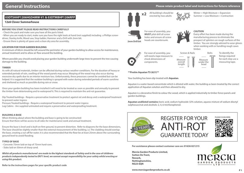
Mercia Garden Products 01DTSHRAX0705SDNW-V1 manual

Mercia Garden Products

Mercia Garden Products 01DTSHRAX0705SDNW-V1 manual

Grosfillex DECO11 Assembly instructions

Grosfillex

Grosfillex DECO11 Assembly instructions

VISSCHER BARCELONA instructions

VISSCHER

VISSCHER BARCELONA instructions

STILLA Master Assembly instructions

STILLA

STILLA Master Assembly instructions

Mercia Garden Products 01PTGRO1006DD-V3 Assembly instructions

Mercia Garden Products

Mercia Garden Products 01PTGRO1006DD-V3 Assembly instructions

Holz-Blech AIDA 40 manual

Holz-Blech

Holz-Blech AIDA 40 manual

Palmako LA28-2127 installation manual

Palmako

Palmako LA28-2127 installation manual

Storite rite 5 Assembly instructions

Storite

Storite rite 5 Assembly instructions

Palmako Ella FR28-6530 installation manual

Palmako

Palmako Ella FR28-6530 installation manual

Milton 8x8 Assembly instructions

Milton

Milton 8x8 Assembly instructions

Best Barns the Elm R Assembly Book

Best Barns

Best Barns the Elm R Assembly Book

Rowlinson Garden Products Balmoral Arbour SS162B Assembly instructions

Rowlinson Garden Products

Rowlinson Garden Products Balmoral Arbour SS162B Assembly instructions

Mercia Garden Products 02DTTWR0605-V1-PEFC General instructions

Mercia Garden Products

Mercia Garden Products 02DTTWR0605-V1-PEFC General instructions

manuals.online logo
manuals.online logoBrands
  • About & Mission
  • Contact us
  • Privacy Policy
  • Terms and Conditions

Copyright 2025 Manuals.Online. All Rights Reserved.