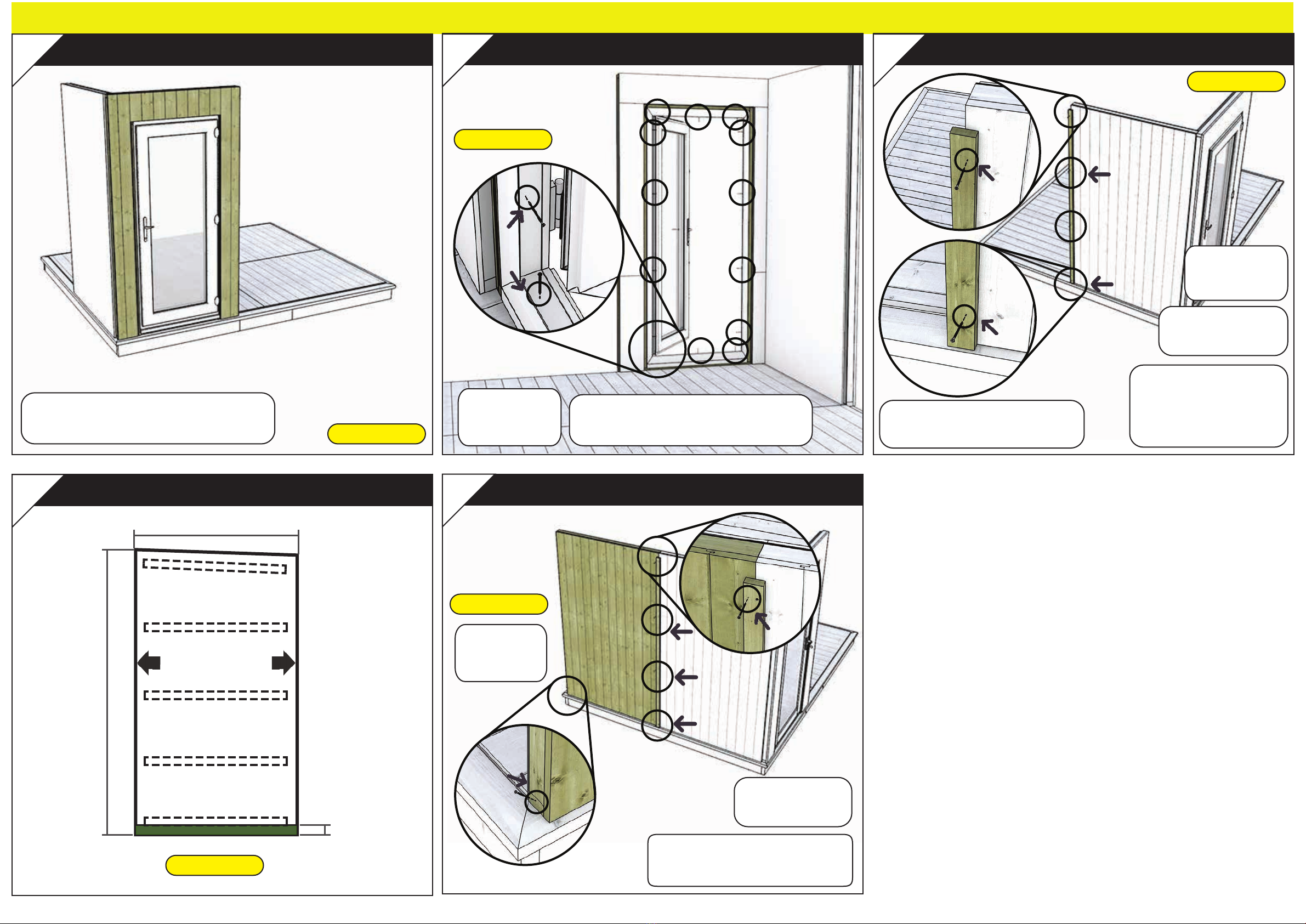
Project Timber Evolution My Den Instruction Manual


Other manuals for Evolution My Den
1
Other Project Timber Garden House manuals

Project Timber
Project Timber Corner Shed Instruction Manual

Project Timber
Project Timber 20x6 Hobbyist Windowed Pent Shed Instruction Manual

Project Timber
Project Timber Hobbyist Instruction Manual

Project Timber
Project Timber Cannes Summerhouse Instruction Manual

Project Timber
Project Timber Evolution My Den 12x8 Instruction Manual

Project Timber
Project Timber Evolution My Den Instruction Manual

Project Timber
Project Timber My Den Metal Roof Instruction Manual

Project Timber
Project Timber Cannes Summerhouse 12x6 Instruction Manual

Project Timber
Project Timber Evolution My Den 8x6 Instruction Manual

Project Timber
Project Timber Evolution My Den 16x8 Instruction Manual

Popular Garden House manuals by other brands


Palmako
Palmako Veronica 4 installation manual

Palmako
Palmako FR34-3832-4 installation manual

OLT
OLT Studio Garden Shed STU128-FJ-Metal Assembly manual

Sunjoy
Sunjoy A102014100 Assembly instruction

Lemeks
Lemeks Palmako FR44-5123 Assembly, installation and maintenance manual

Palmako
Palmako FR28-7030-1 Assembly, installation and maintenance manual