Projoy Electric PEFS-EL Series User manual

www.projoy-electric.com
Installation
Guide
PEFS-EL Series

www.projoy-electric.com
User Manual of Projoy Fire Fighter Safety Switch (FFSS)
1. Scope and General
2 Important Safety Precautions
3 Using of FFSS
4 Shutdown Ways
5 Specifications of FFSS
6 Installation
7 PID Recovery Function (Optional)
8 Aftersales service and warranty
1
1
1
2
2
3
6
7
PEFS-EL Series
CONTENTS
9 Contact us 7

1 Scope and General
2 Important Safety Precautions
This manual is used for PEFS-EL Series of Fire Fighter Safety Switch (FFSS).
Version Date Remark Chapter
V1.0 2021-10-15 First Edition -
www.projoy-electric.com
PEFS-EL Series
1
1. Changes or modifications not explained/approved in this manual avoids your authority to operate this equipment.
2. PROJOY shall not be held responsible for any damage caused by incorrect installation and/or the misunderstanding of this
manual.
3. PROJOY reserves the right to make modification to this manual or the information contained herein at any time without
notice.
4. No design data such as sample pictures provided in this manual should be modified or duplicated except for personal use.
5. Check the system regularly every 3 months
Components in the installations are exposed to high voltages and currents.
Follow these instructions carefully to avoid the risk from fire or electric shock.
The following regulations and standards are applicable and must be read before installation:
1. Wiring should be done by professional and qualified people;
2. Wiring should be done after confirming of complete disconnection of power supply;
3. International Standards: IEC 60364-7-712 Electrical installations requirements of PV system.
4. Local building regulations.
5. Guidelines for lightning and over voltage protection.
Note!
1. It is essential to maintain voltage and current limits under all possible operating conditions. Also keep in mind the literature
on the correct dimensions and dimensions of cables and components.
2. The installation of such equipment should only be carried out by certified technicians.
3. The wiring schematics of the Firefighter Safety Switch can be found at the end of this manual.
4. All installation works shall be tested in accordance with relevant local laws and regulations during installation.
V2.0 2022-04-20 Content Modified 6 Installation
V2.1 2022-05-18 Content Modified 4 Shutdown Ways
V2.2 2022-06-23 Content Modified 6 Installation
V2.3 2022-08-01 Content Addition 7 PID Recovery Function
3.1 Using of the Rapid Shutdown
The Rapid Shutdown was developed as a safety device for disconnecting the DC strings, when emergency case occurs, like
fire.
3.2 Installation of the Rapid Shutdown
The Rapid Shutdown should to be placed as close to the solar array as possible, which is IP65 for outdoor installation.
3 Using of FFSS
www.projoy-electric.com
PEFS-EL Series
2
4 Shutdown Ways
5 Specifications of FFSS
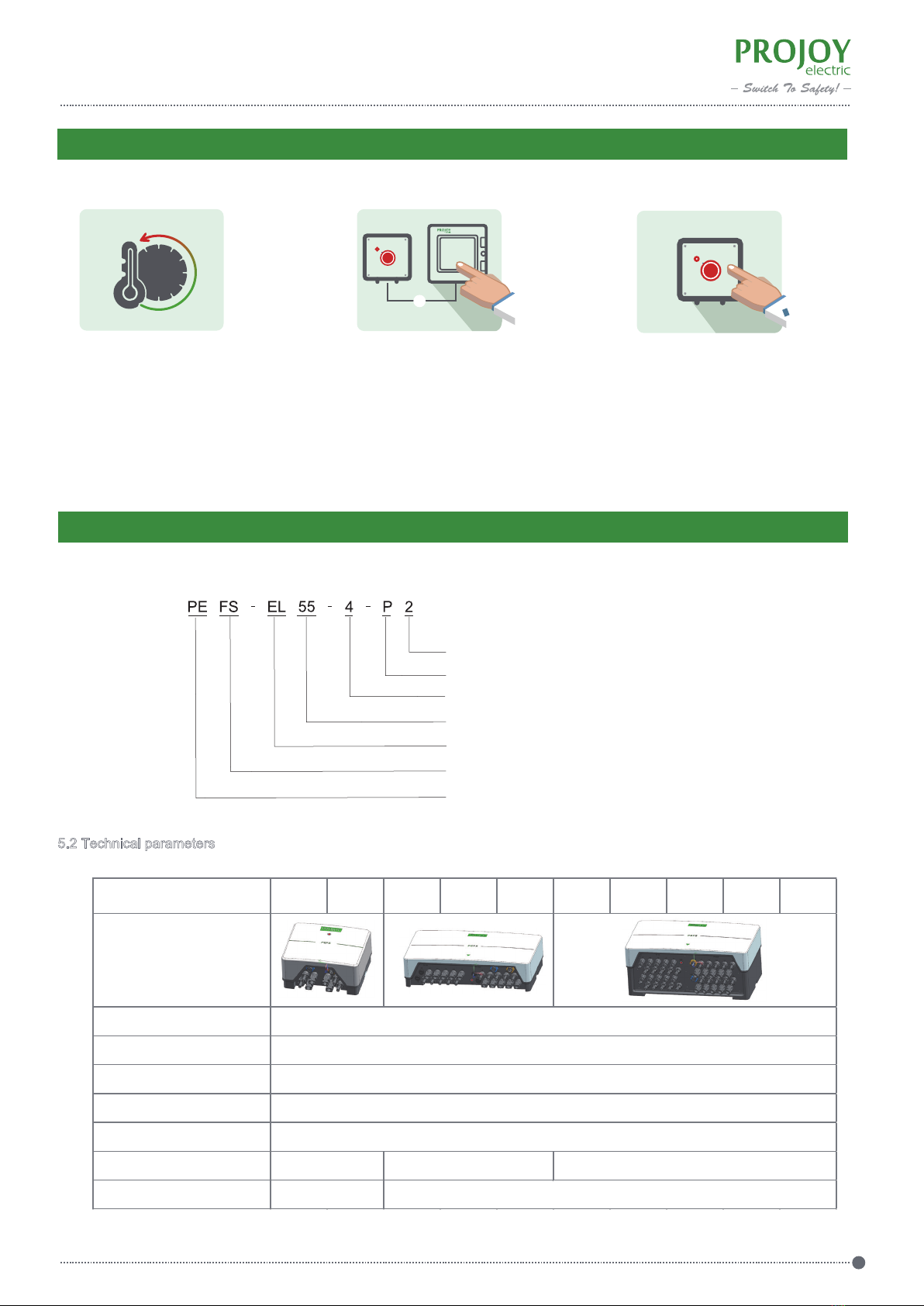
5.1 Description
5.2 Technical parameters
2: Generation 2
4: Number of poles
55: Frame Rating
FS: Design Code
PE: Brand Code
P: Plastic enclosure
EL: Product Code
Number of poles 2 4 6 8 10 12 14 16 18 20
Appearance
Frame Rating In(A)
Working temperature
Fiducial temperature
Pollution degree
Protection class
Outline dimensions(mm)
Installation dimensions(mm)
3
IP65
210×200×100 375×225×96 375×225×162
Φ6×436Φ6×269
16、25、32、40、50、55
-40~+70℃
+40℃
Shutdown By Tem. By AC Power cut-off By Manual
×
70°
Automatically shutdown
when detecting ambient
temperature is over
than 70℃.
Automatically shutdown
by pressing emergency
stop button
Automatically shutdown
by AC power cut-off

www.projoy-electric.com
PEFS-EL Series
3
5.3 Wiring Options
Number of poles 2 4 6 8 10 12 14 16 18 20
Appearance
3-core wire
MC4 cable 4 8 12 16 20 24 28 32 36 40
1 *1.2m for AC power supply
6 Insatllation
6.1 Installation Requirements
6.2 Installation Steps
2) Mount the switch enclosure on the wall.
Open the box, take out PEFS, read this manual, and prepare cross/straight screwdriver.
1) Pull out the bottom bracket
www.projoy-electric.com
PEFS-EL Series
4
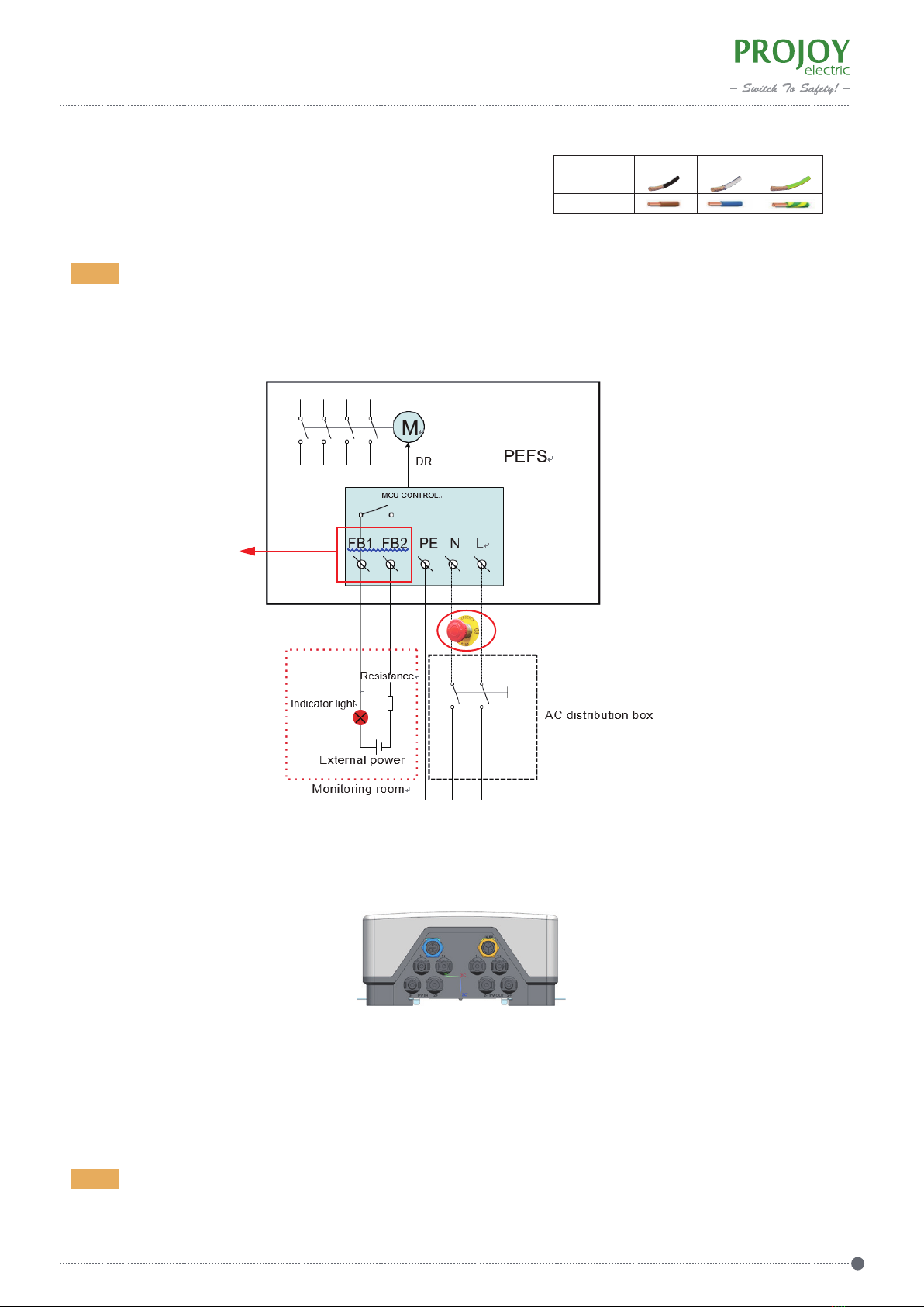
FB1, FB2 function is optional.
FB1, FB2 are used to remotely display the on/off status of the switch. When the switch is closed, FB1 is connected
to FB2; when the switch is open, FB1 is disconnected from FB2.
Resistor and indicator selected should be depending on power supply voltage and current, and should be less than 320mA
4) Wiring and connectors
Please follow the marks (1+, 1-, 2+, 2- ) for PV wiring.
Note!
Emergency Button (Optional)
5) Installation
Note!
Do not expose it to direct sunlight and should be with good ventilation condition.
3) Wiring AC cable
Wire Color: According to American and Europe standard requirements.
US: L: Black; N: White; G: Green
EU: L: Brown; N: Blue; G: Green-Yellow
L N G
US
EU
(Optional)
www.projoy-electric.com
PEFS-EL Series
5
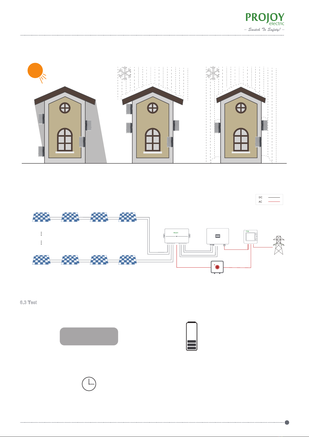
6.3 Test
1) Step1. Activate AC power (Capacitors charging).
AC POWER ON
2) Step 2. Wait for one minute for the first time, motor drives switch to turn on and LED indicator light on
Approx. 1 min
√√
√
×
√√
√
×
√
××
6) Diagram
1-10 strings
Distribution box
Firefighter Safety Switch Inverter
Grid
PV Arrays
PV Arrays
Emergency Button (optional)
+
-
+
-

3) Step 3. Deactivate AC power. Motor drives switch to turn off and LED indicator light off
AC POWER OFF
Approx. 7 sec.
4) Step 4. Again activate AC power circuit. motor drives switch to turn on and LED indicator light on
AC POWER ON
Approx. 8 sec.
5) Step 5. Test is completed.
7 PID Recovery Function (Optional)
www.projoy-electric.com
PEFS-EL Series
6
7.1 PID can be understood as a sign of ageing
The so-called PID (Potential Induced Degradation) of photovoltaic panels is an effect that affects the potential of the modules
with respect to the ground and that affects the power of the module by reducing it consistently over time.
The main cause of PID is considered to be the high voltage between the encapsulated solar cells and the front glass surface,
which is grounded through the frame or substructure.
This can lead to an unwanted migration of the charge carriers (ions / electrons), that reduces the performance of the cell. In
case of high voltages due to long string connections, the PID effect can also occur more heavily. High humidity and
temperature accel-erate this process.
PID is a highly critical concern, because it generally only develops months after the installation of the photovoltaic system. And
in addition to that, unlike other module defects (such as delamination or yellowing of EVA parts), the PID is not distinguishable
with the naked eye.
7.2 Projoy PID solution
Projoy FF Box with PID recovery function can inject mA current at 600Vdc between negative electrode and the earth on
solar modules via solar inverter negative common bus.
FF starts up & shutdown automatically when detecting string voltage less & more than 30Vdc.
It requires solar module must be P crystalline silicon type.

8 Aftersales service and warranty
www.projoy-electric.com
PEFS-EL Series
7
8.2 Aftersales service
1) Please contact Projoy local distributors for after-sales service
1) Inappropriate use or installation, self-modification or improper maintenance, etc.:
2) Beyond the prescribed scope of use;
3) Earthquakes, fires, lightning strikes, abnormal voltages, other natural disasters and secondary disasters, etc.
9 Contact us
Projoy Electric Co., Ltd.
Tell:+86-512-6878 6489
Web: https://en.projoy-electric.com/
Add: 2nd Floor, Building 3, No. 2266, Taiyang Road, Xiangcheng District, Suzhou
Static Power
Operating Power
Max. Power
Rated Output Voltage To Ground
Rated Output Current
Max. Short Circuit Current
Max. System Volatage
Minimum Insulating Impendance
Module Type Required
Operating Temperature Range
Operating Relative Humidity
Max. Altitude Without Derating
<0.5W
3.75W
8.75W
600V
3.3mA
6.7mA
1500V
P Crystalline Silicon Type
200kΩ
-40°C~+70°C
0%~98%
4000m
AC Input
DC Output
PV Modules And
Inverter Requirements
Other Info
8.1 Warranty
Projoy PEFS Series Module Level Rapid Shutdown Device: 10 years standard warranty and up to 25 years extension, which
commencing from 3 months later of the manufacturing date. PROJOY will repair or replace any fault unit which is damaged
or cannot work normally due to product quality issue. However, for the faults caused by following reasons, PROJOY would
do service with charge even under warranty.
7.3 Datasheet
Table of contents
Other Projoy Electric Solar Panel manuals


