Prokan BS04-BI-LP Owner's manual
1 | Page
Manual # PK000442021AE- Date: 2022/06
Assembly Instructions & User’s Manual for
Item Number: K04000320A Model Number: BS04-BI-LP
30" Double access drawers kit Item Number: K01000321A
DANGER
!!
1.
2.
3.
4.
If you smell gas:
Shut off gas to the appliance.
Extinguish any open flame.
Open lid.
If odor continues, keep away from
the appliance and immediately call
your gas supplier or your fire
department.
Do not store or use g asoline or other
flammable liquids or vapors in the
vicinity of this or any other appli-
ances.
An LP cylinder not connected for
use shall not be stored in the vicinity
of this or any other appliance.
1.
2.
!
!WARNING
Customer Assistance (spare/replacement parts): 1-877-419-2598 or
OPERATOR'S MANUAL
801480
THIS ASSEMBLY MANUAL CONTAINS IMPORTANT SAFETY
INFORMATION. PLEASE READ AND KEEP FOR FUTURE REFERENCE.
Pro Elite 4B Built-in Grill
Item Number: K04000319A K04000345A Model Number: BS04R-BI-LP
BS04-BI-LP
BS04R-BI-LP 30" Double access drawers kit
BS04RFIS-LP-A
BS04RCIS-LP-A
78" Pro Elite 4B Golden White Grill Island
Item Number: K04000342A Model Number: BS04RFIS-LP-A
60" Pro Elite 4B Golden White Q Grill Island
Item Number: K04000343A Model Number: BS04RCIS-LP-A
78" Pro Elite 4B European Ledge Island Grill

Quality Statement..................................................................................................................................... 3
Important Safety Information................................................................................................................ 4
Package Contents ....................................................................................................................................7
Product Information................................................................................................................................8-9
Components .............................................................................................................................................10
Tools............................................................................................................................................................11
Assembly Instructions............................................................................................................................12-19
Warning........................................................................................................................................29
Troubleshooting....................................................................................................................................... 31-33
Care & Use Instructions ........................................................................................................................ 34-41
Storage Instructions ................................................................................................................................42
2 | Page
Table of Contents
Part Diagrams and Lists........................................................................................................................ 20-28
Natural Gas Safety Instructions.............................................................................................................5
Danger.......................................................................................................................................... 30
Technical Data .......................................................................................................................................... 43
Warranty Information ............................................................................................................................. 44
Full System Features...............................................................................................................................6

Important Safety Information
•Please read all instructions carefully before assembling this product.
•Where applicable, and for your safety, assembly by an adult is strongly recommended.
•Use only vendor-supplied hardware to assemble this item. Using unauthorized hardware
could jeopardize the structural integrity of the item.
•Hardware may loosen overtime. Periodically check that all connections are tight.
Before Assembly
•Remove all parts and hardware from the box. Place all items on a carpeted or
scratch-free work surface, as this will avoid damaging parts during assembly.
•The shipping box can provide an ideal work surface if none is available.
•Use the components and hardware lists below to identify, inventory and separate
each of the hardware and components included.
•To avoid accidentally discarding small components or hardware, do not dispose
of any packaging or contents of the shipping carton until assembly is complete.
•DO NOT USE power tools unless it is explicitly identified in this manual as
required for use during assembly. Power tools can damage the fasteners,
hardware and/or components.
•Do not fully tighten all fasteners / screws until all parts are in place. Failure to
follow these instructions may cause the fasteners / screws to misalign during
assembly.
Care & Use
•Use a soft, clean cloth that will not scratch the surface when cleaning.
3 | Page
Quality Statement

4|P a ge
!
For safe operation ensure the Gas Valve Assem-
bly Orifice is inside the Burner Tube before using
your grill. See figure. If the Orifice is not inside
the Burner Tube, lighting the Burner may cause
explosion and/or fire resulting in serious bodily
injury and/or property damage.
METHOD 1: Bend a stiff wire or wire coat hanger
into a small hook as shown and run the hook
through the Burner Tube and inside the Burner
several times to remove debris.
METHOD 2: Use a bottle brush with a flexible
handle and run the brush through the Burner
Tube and inside the Burner several times to
remove any debris.
METHOD 3: Use an air hose to force air through
each Burner Tube. The forced air should pass
debris or obstructions through the Burner and out
the Ports.
2. Carefully lift each Burner up and away from the Gas
Valve Orifice.
Remove the screws from the rear of each Main Bur ner
using a Phillips Head Screwdriver or wrench.
3.
4. Refer to the figure below and perform one of these
3 cleaning methods:
Check and clean Burner/Venturi Tubes for insects
and insect nests. A clogged tube can lead to a fire
beneath the grill.
WARNING: Grease can get very hot. Always handle the Grease
Tray with a flame retardant BBQ mitt. Before removing the
Tray, always be sure that the grill has properly cooled. Be
aware that the tray does contain grease and be extremely
careful when removing the tray to prevent spillage. Failure to
follow these instructions could cause serious bodily injury or
property damage.
Grill Installation Codes
The installation must conform with local codes or, in the
absence of local codes, with either the National Fuel
Gas Code, CSA/ANSI Z21.58-2022 • CSA 1.6-2022.
•
•
•
PRE-ASSEMBLY
Read and perform the following pre-assembly instruc-
tions:
Tools Required for Assembly:
You will need assistance from another person to
handle the grill head and other large and heavy parts.
Open lid of shipping carton. Remove top sheet of
cardboard and packing materials. Lay cardboard sheet
on floor and use as a work surface to protect floor and
grill parts from scratches.
You may slice the carton front corners with a utility knife
to lay open the carton front panel. This allows you to
raise the Lid and remove the components packed in-
side, making it easier to lift.
Use the Hardware and Part Diagrams to ensure all items
are included and free of damage.
Do not throw away the bags of hardware that are in-
cluded with boxed parts. These are required for assem-
bly.
Do not assemble or operate the grill if it appears dam-
aged. If there are damaged or missing parts when you
unpack the shipping box or you have questions during
the assembly process call 1-877-419-2598;
email:[email protected]/
[email protected] Monday through Friday from
8:00 a.m. to 8:00 p.m. EST
protective work gloves
protective eyewear
Phillips Head Screwdriver
CAUTION !
To reduce the chance of FLASHBACK FIRE you must
clean the Burner Tubes at least once a month in summer
and fall or whenever spiders are active in your area, and if
your grill has not been used for an extended period of
time.
!
Never cover or wrap the Cooking Grids, bottom
of the Grill Bowl, or Grease Tray with aluminum
foil or any other material that will absorb grease.
TO CLEAN BURNER TUBE,
INSERT HOOK
HERE
Burner Tube
9
Burner Port Foot
Gas Valve Assembly Orifice Burner Tube
Failure to comply with these instructions may result
in a hazardous situation which, if not avoided, may
result in injury.
Spiders and small insects can spin webs and nest
in the grill Burner Tubes during transit and ware-
housing which can lead to a gas flow obstruction
resulting in a fire in and around the Burner Tubes.
This type of "FLASHBACK FIRE" can cause serious
grill damage and create an unsafe operating con-
dition for the user.
To reduce the chance of FLASHBACK FIRE
you must clean the Burner Tubes as follows
before initial use. Also do this at least once a
month in summer and fall or whenever spiders are
active in your area, and if your grill has not been
used for an extended period of time.
1.
! CAUTION
CAUTION !!
Important Safety Information
5|P a ge
•Your Natural Gas BBQ is designed to operate on
Natural Gas only, at a pressure of 7" water column
(W.C.) (1/4 psig or 1.75 kpa), regulated at the
residential meter. Check with your gas utility com-
pany for local gas pressure and with your local
municipality for building code requirements. If your
residential gas line pressure has not been
regulated to 7" W.C., contact your local gas utility
company for professional assistance.
•The gas pressure Regulator supplied with
this appliance must be used. This Regulator is
set for an outlet pressure of 4" W.C.
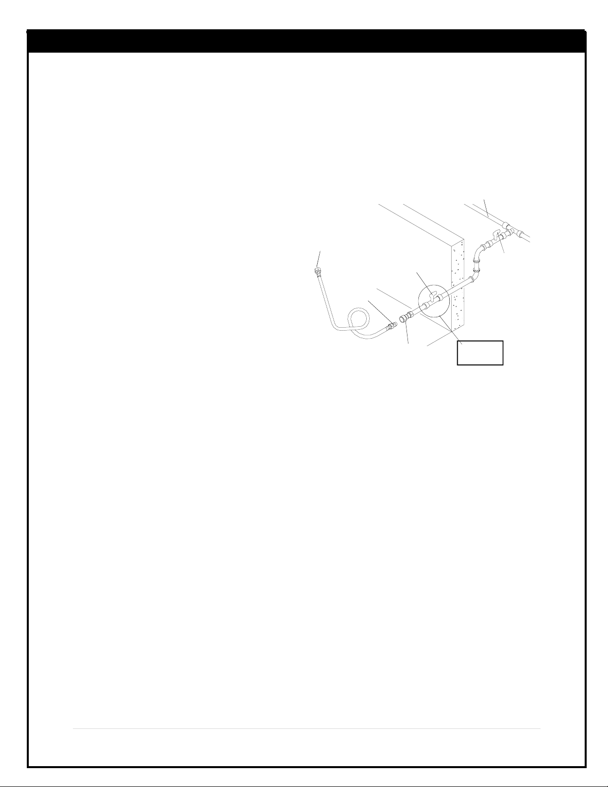
•It is recommended that a Shut Off Valve be installed
at the gas supply source outdoors. Install at a point
after the gas pipe exits the outside wall and before the
Quick Disconnect Hose, or install it at the point
before the gas line piping enters the ground. See
Figure 1.
•Pipe sealing compound or pipe thread tape resistant
to the action of Natural Gas must be used on all male
pipe threads when making the connection.
•Disconnect your gas BBQ from fuel source when
the gas supply is being tested at high pressures.
This gas BBQ and its individual Shut Off Valve must
be disconnected from the gas supply pipe system
during any pressure testing of that system at
pressure in excess of 1/2 psi (3.5kpa).
•Turn off your gas BBQ when the gas supply is
tested at low pressures. The BBQ must be
isolated from the gas supply pipe system
by closing its individual Manual Shut Off
Valve during any pressure testing of the gas
supply pipe system at pressures equal
to or less than 1/2 psi (3.5kpa).
•The Quick Disconnect connects to a 3/8 inch
NPT thread from gas source. The Quick
Disconnect fitting is a hand operated device
that automatically shuts off the the flow of
gas from the source when it is disconnected.
•The Dust Covers (plastic plugs) provided with
the Quick Disconnect help keep the open
ends clean while disconnected.
•The outdoor connector must be firmly attached to
a ridged permanent construction.
•The Quick Disconnect MUST BE installed above
ground.
•WARNING: Do not route the 10 foot Quick
Disconnect Hose under a deck. The hose must
be visible and inspected prior to each grill use.
Figure 1
(For Natural Gas Model Only)
If the length of line required does not exceed 50 feet, use
a 5/8" O.D. tube. One size larger should be used for
lengths greater than 50 feet.
Gas piping may be copper tubing, type K or L; polyeth-
ylene plastic tube, with a minimum wall thickness of .
062 inch; or standard weight (schedule 40) steel or
wrought iron pipe.
Copper tubing must be tin-lined if the gas contains more
than 0.3 grams of hydrogen sulfide per 100 cubic feet
of gas.
Plastic tubing is suitable only for outdoor, underground
use.
Gas piping in contact with earth, or any other material
which may corrode the piping, must be protected
against corrosion in an approved manner.
Underground piping must have a minimum of 18"
cover.
Gas Line Piping
Test Connections
NATURAL GAS SUPPLY
QUICK
DISCONNECT
INSIDEWALL
OUTSIDEWALL
MALE
FITTING
TO NATURAL GAS
REGULATOR
LOCKING GAS
SHUT OFF VALVE
LOCKING
GAS
SHUT OFF
VALVE
Additional
Hardware Not
Included
All connections and joints must be thoroughly tested
for leaks in accordance with local codes and all
listed procedures in the latest edition of CSA/ANSI
Z21.58-2022 • CSA 1.6-2022.
•The Quick Disconnect fitting can be installed
horizontally,or pointing downward.DO NOT
install the fitting with the opening pointing
upward because the fitting could collect water
and debris.
Natural Gas Safety Instructions
6|P a ge
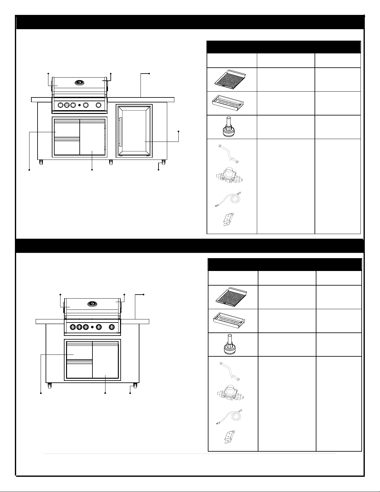
Full System Features-BS04-BI-LP/BS04RFIS-LP-A
Full System Features-BS04RCIS-LP-A
Main Burner:40,000 BTU
Rear Burner:12.000 BTU
Full Rust-Proof Cast
Aluminum Firebox Weather
Resistant
Countertop
63L Fridge
Caster for Easy
Mobility
Propane Tank
Storage or Natural
Gas Line (Optional)
Double Access
Drawers
Main Burner:40,000 BTU
Rear Burner:12.000 BTU
Full Rust-Proof Cast
Aluminum Firebox Weather
Resistant
Countertop
Caster for Easy
Mobility
Propane Tank
Storage or Natural
Gas Line (Optional)
Double Access
Drawers
Component Description Part#
Grill Topper
Charcoal Insert
Self-Leveling
Adjustable Legs
KPSS002
S0221-13
Sold Separately
KPSS004
KPSS005
Natural Gas Conversion Kit
Component Description Part#
Grill Topper
Charcoal Insert
Self-Leveling
Adjustable Legs
KPSS002
S0221-13
Sold Separately
KPSS004
KPSS005
Natural Gas Conversion Kit
7|P a ge
H
E
B
F
C
A
B
D
B
Quantity
A
B
C
D
E
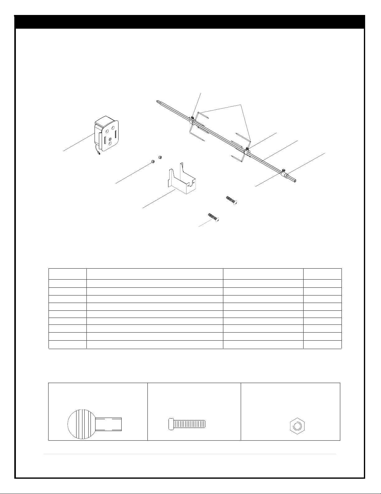
Component Description PAR T#
Rot. Collar
Rot. Thumbscrew 1/4"x1/2"
Rot. Spit
Rot. Holding Fork
Rot. Motor Bracket
Rot. Motor/AC
Rot. Screw#10-24x1"UNC
Rot. Nut #10-24
1
3
1
2
1
1
2
2
P05508200A
S196G04081
S0207-137
P05508023A
P05508226A
P07101050B
S112G10121
S362G10121
F
G
H
Rot. Thumbscrew 1/4"x1/2", (B)
Part No. S196G04081
Qty: 3
Rot.Screw#10-24x1"UNC(G)
Part No. S112G10121
Qty: 2
Y0250200BP Rotisserie Assembly Parts List
Rot. Nut #10-24(H) Part
No. S362G10121
Qty: 2
Hardware for Rotisserie
Package Contents
Y0250200BP Rotisserie Assembly Parts Diagram
IMPORTANT: Please note that the rotisserie rod is packed on the back
of the grill box.
G
8|P a ge
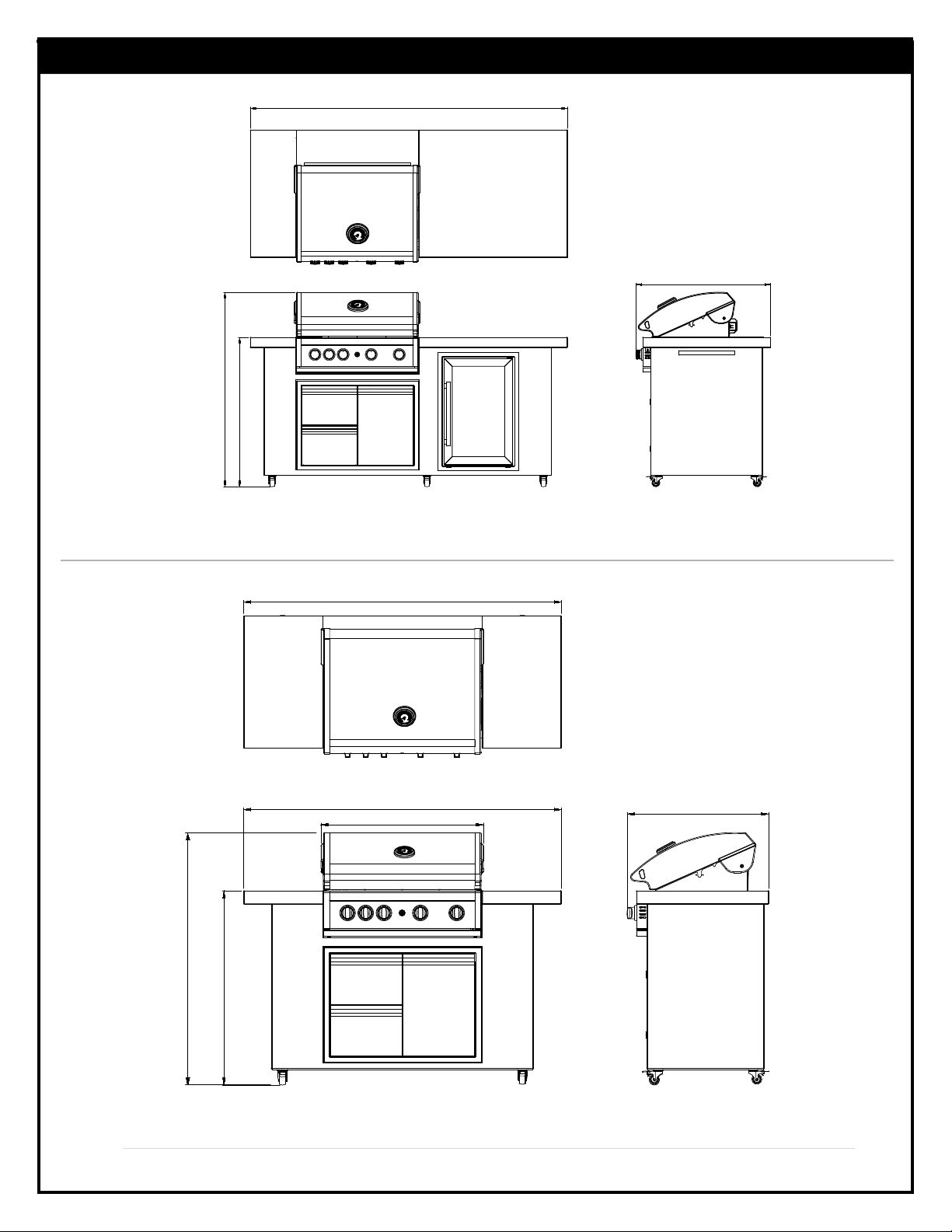
Product Information
78.3"
47.92"
33.17"
36.87"
BS04-BI-LP
BS04RFIS-LP-A
605"
30.94"
26.95"
60.5"
37.02"
BS04RCIS-LP-A
47.92"
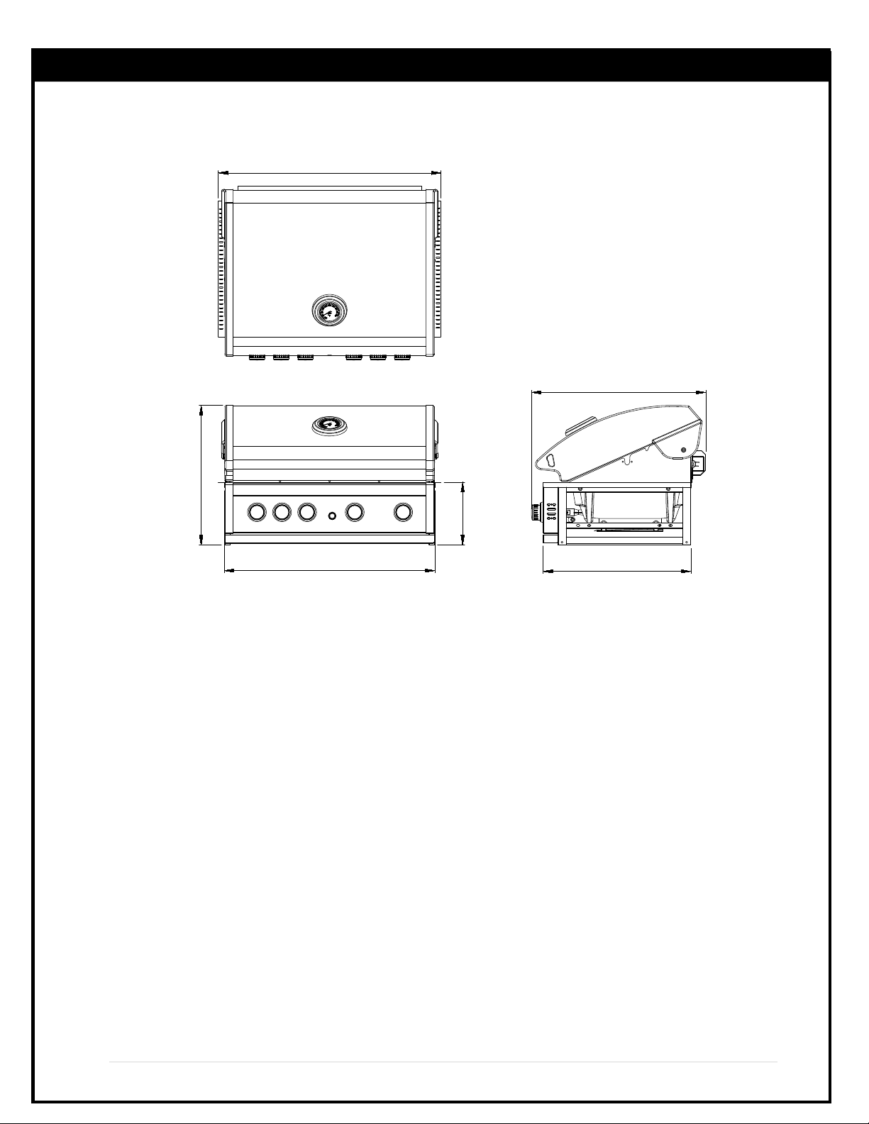
9|P a ge
Product Information
30.2"
9"
31.9"
25"
21.14"
20.01"

Components
lame amer
No.S0224-06
Qty 4
Cooking Grid
No.S0224-08
Qty 2
Warming Rack
No.S0224-09
Qty 1
10|P a ge
Components
Qty 1
Fridge
No.S0226-05

11|P a ge
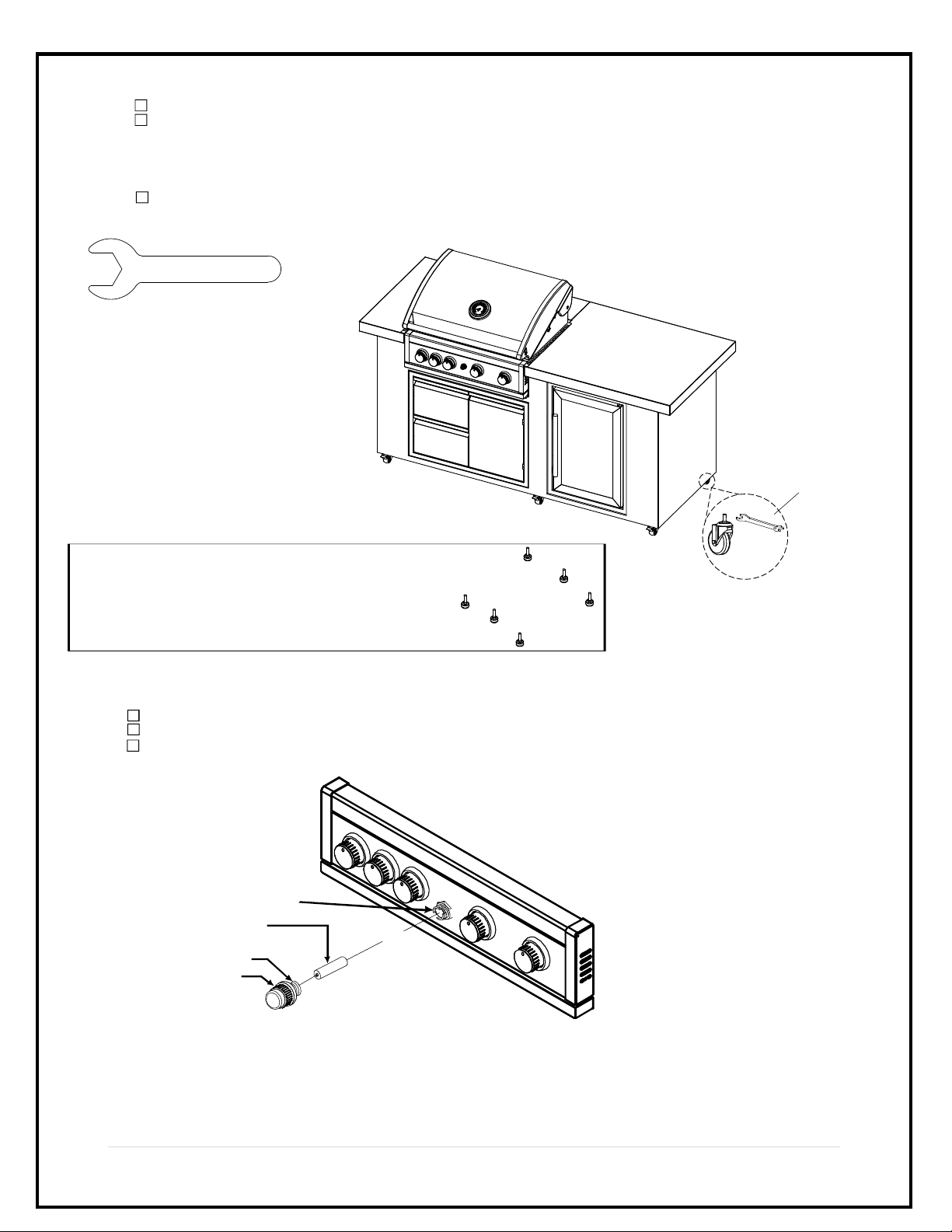
Tools
Caster Wrench Phillips Screwdriver (Not
Included)

12| P a ge
Step 1: Connect regulator to propane tank.
ASSEMBLY BS04-BI-LP/BS04RFIS-LP-A
CAUTION : To assemble this grill, you should obtain assistance from another person when handling some of
the larger, heavier pieces.
13| P a ge
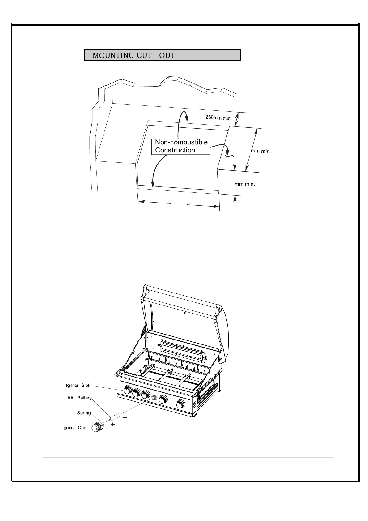
6 Install Ignitor Battery
Remove Ignitor Cap from Control Panel.
Place supplied AA battery into the Ignitor Slot with positive pole facing you.
Position the Cap and Spring over the AA battery and tighten onto Control Panel.
NOTE: CORRECT BATTERY USE
Always purchase the correct size and grade of battery most suitable for the intended use.
Replace all batteries of a set at the same time.
Clean the battery contacts and also those of the device prior to battery installation.
Remove batteries from equipment which is not to be used for an extended period of time.
Remove used batteries promptly.
•
•
•
•
•
Ignitor Cap
Ignitor Slot
AA Battery
Spring+
-
Adjustable Level are located underside of the Island Assembly as shown.
If the Island sets are not level with each others, adjust the 6 preassembled Adjustable
Level using the wrench provided.
- Turn the adjusters clockwise to raise the height of the Island.
- Turn the adjusters counterclockwise to lower the Island.
After leveling, double check for making sure that all the adjusters touch the ground.
IMPORTANT: For illustration purpose the Island Assembly Set is shown on a tilted
angle. FOR YOUR SAFETY, DO NOT TILT your Island Assembly at any time.
wrench
Caster Wrench
Step 3:
Step 2:
Self-Leveling adjustable legs: Sold separately.
(Manufacturer part #: S0202-15).
14 |P a ge
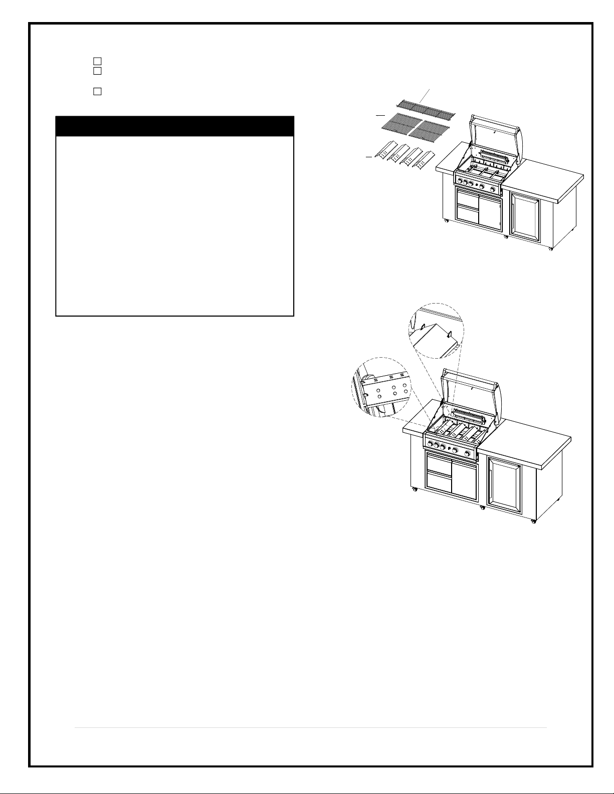
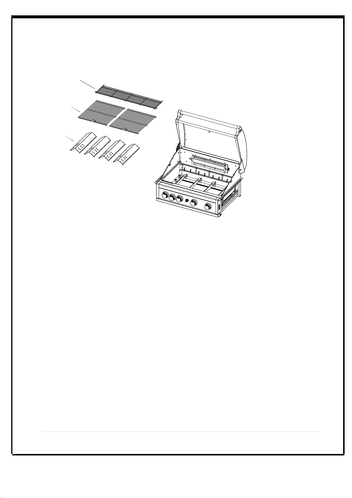
Install Cooking Components
Place the Flame Tamers above the Burners.
Place the Cooking Grids on the ledge
above the Flame Tamer.
Place the Secondary Cooking Rack onto
the Warming rack holder.
Final Grill Assembly Step
When you have finished assembling your grill
be sure that all things are correctly positioned
for safe operation of your grill.
Before each use of the grill, make sure the
Grease Tray is fully placed under the Grill Bowl.
CAUTION: Before each use of your grill, inspect
the Grease Tray, Flame Tamer and inside of the
Grill Bowl to be sure there is no excessive grease
and debris buildup. Clean the Grease Tray, Flame
Tamer and inside of the Grill Bowl frequently to
eliminate grease/debris build-up and to prevent
grease fires.
Step 4:
Cooking Rack
Part No.S0224-09
Qty 1
Cooking Rack
Part No.S0224-08
Qty 2
Flame Tamers
Part No.S024-06
Qty 4

15|P a ge
1. Remove all components from the carton.
Attach the Motor Bracket on the outside of the left grill bowl panel. Align the two holes of the Bracket with the
holes on the grill bowl panel. Tighten securely using two Screws #10-24x1" UNC and Nuts provided.(Fig. 1)
Attach the Collar Support Bracket with a threaded screw over the middle hole on the right grill bowl panel.
Tighten securely using a wing nut provided.
2.
Rot. Screw #10-24x1" UNC x2
Rot. Nut #10-24 x2
Step 5:
Fig. 1
Motor Bracket
Left Grill
Bowl Panel
Washer3/16"
Qty.2

Install the AC (alternating current) Rotisserie Motor onto the Motor Bracket as shown below. Be sure
the Motor attaches to the Bracket with the electrical cord down.
BEFORE rotisserie cooking you will need to remove the
Cooking Rack/Secondary from your grill. When rotisserie cooking
place a Cooking Pan under the food to be cooked. This
will capture the drippings and keep your grill clean of excess
grease which could cause a fire. Use caution when moving
a Cooking Pan containing hot oils.
The Collar must always be used with
this Rotisserie
Insert the assembled Rotisserie into the Motor as shown below. The Motor should be on the left side of your grill.
Place the Collar into the slot opening on collar support bracket, then tighten the Collar Thumbscrew on the left end of
Collar. The Collar will stabilize the Rotisserie during the cooking process and allows the Rotisserie Spit to turn
smoothly. Plug the Rotisserie Cord into the GFCI outlet and plug the GFCI Power Cord to a properly grounded outlet,
then turn on to test.
Collar
Holding Forks Thumbscrew
Motor
Thumbscrew
16 | P a ge
Step 6:
Step 7:
Rotisserie
Motor

17 | P a ge
ASSEMBLY BS04R-BI-LP
Step 1: Install the Trim brackets .
Step 2: Install the grill onto the housing.
Phillips Head Screw
1/4" x 3/8"
Qty. 4
18 | P a ge
775 -785mm
537
228
Step 3: Ignition Battery.
19 | P a ge
Step 4: Cooking Component Installation.
Cooking Grid
Warming Rack
Flame Tamer

20 | P a ge
Part Diagrams and Lists-BS04R-BI-LP
5
2
1
6
7
8
9
10
11
12
13
14
15
16
17
18
19
27
21A
21B
22
23
26
28
1
2
29 30
31
32
33
34
35
36
37
38
39
40
3
4
41
This manual suits for next models
9
Table of contents
Other Prokan Grill manuals


Popular Grill manuals by other brands


Electri-Chef
Electri-Chef 4400-EC-448-I-D-32 Features

BURNHARD
BURNHARD BARNEY DELUXE manual

Koenig
Koenig RP418 instruction manual

FireMagic
FireMagic CHOICE C430S Installation instructions and owner's manual

Silvercrest
Silvercrest 93460 operating instructions

Louisiana Grills
Louisiana Grills LGK22 Assembly and operation