PROMAT TROTEC BD21 User manual

TRT-BA-BD21-BD26-TC2015-40-004-EN
BD21 / BD26
EN
OPERATING MANUAL
LASER DISTANCE MEASURING
DEVICE
2 EN
laser distance measuring device BD21 / BD26
Table of contents
Notes regarding the operating manual.................................2
Safety .....................................................................................2
Information about the device................................................4
Transport and storage...........................................................6
Operation ...............................................................................6
Maintenance and repair ......................................................11
Errors and faults..................................................................11
Disposal ...............................................................................12
Notes regarding the operating manual
Symbols
Warning of laser radiation
This symbol indicates dangers to the health of persons
due to laser radiation.
Warning
This signal word indicates a hazard with an average
risk level which, if not avoided, can result in serious
injury or death.
Caution
This signal word indicates a hazard with a low risk
level which, if not avoided, can result in minor or
moderate injury.
Note
This signal word indicates important information (e.g.
material damage), but does not indicate hazards.
Info
Information marked with this symbol helps you to carry
out your tasks quickly and safely.
Follow the manual
Information marked with this symbol indicates that the
operating manual must be observed.
You can download the current version of the operating manual
and the EU declaration of conformity via the following link:
BD21
https://hub.trotec.com/?id=31522
BD26
https://hub.trotec.com/?id=31523
Safety
Read this manual carefully before starting or using the
device. Always store the manual in the immediate vicinity
of the device or its site of use.
Warning
Read all safety warnings and all instructions.
Failure to follow the warnings and instructions may
result in electric shock, fire and/or serious injury.
Save all warnings and instructions for future
reference.
This appliance can be used by children aged from
8years and above and persons with reduced physical,
sensory or mental capabilities or lack of experience
and knowledge if they have been given supervision or
instruction concerning use of the appliance in a safe
way and understand the hazards involved.
Children shall not play with the appliance. Cleaning and
user maintenance shall not be made by children
without supervision.
• Do not use the device in potentially explosive rooms or
areas and do not install it there.
• Do not use the device in aggressive atmosphere.
• Do not immerse the device in water. Do not allow liquids to
penetrate into the device.
• The device may only be used in dry surroundings and must
not be used in the rain or at a relative humidity exceeding
the operating conditions.
• Protect the device from permanent direct sunlight.
• Do not remove any safety signs, stickers or labels from the
device. Keep all safety signs, stickers and labels in legible
condition.
EN 3
laser distance measuring device BD21 / BD26
• Do not open the device.
• Avoid looking directly into the laser beam.
• Never point the laser beam at people or animals.
• Only use the device, if sufficient safety precautions were
taken at the surveyed location (e.g. when performing
measurements along public roads, on building sites etc.).
Otherwise do not use the device.
• Observe the storage and operating conditions as given in
the Technical data chapter.
Intended use
Only use the device for measuring distances, areas and volumes
by means of the integrated laser and within the measuring
range specified in the technical data. Observe and comply with
the technical data.
To use the device for its intended use, only use accessories and
spare parts which have been approved by Trotec.
Improper use
Do not use the device in potentially explosive atmospheres, or
for measurements in liquids. Never point it at people or animals.
Trotec accepts no liability for damages resulting from improper
use. In such a case, any warranty claims will be voided.
Any unauthorised modifications, alterations or structural
changes to the device are forbidden.
Personnel qualifications
People who use this device must:
• be aware of the dangers that occur when working with
laser measuring devices.
• have read and understood the operating manual, especially
the Safety chapter.
Residual risks
Warning of laser radiation
Laser class2, Pmax.: <1mW, λ: 400-700nm,
EN60825-1:2014
Do not look directly into the laser beam or the opening
from which it emerges.
Never point the laser beam at people, animals or
reflective surfaces. Even brief eye contact can lead to
eye damage.
Examining the laser output aperture by use of optical
instruments (e.g. magnifying glass, magnifiers and the
like) entails the risk of eye damage.
When working with a laser of class2, observe the
national regulations on wearing eye protection.
Warning
Risk of suffocation!
Do not leave the packaging lying around. Children may
use it as a dangerous toy.
Warning
The device is not a toy and does not belong in the
hands of children.
Warning
Dangers can occur at the device when it is used by
untrained people in an unprofessional or improper way!
Observe the personnel qualifications!
Caution
Keep a sufficient distance from heat sources.
Note
To prevent damages to the device, do not expose it to
extreme temperatures, extreme humidity or moisture.
Note
Do not use abrasive cleaners or solvents to clean the
device.
4 EN
laser distance measuring device BD21 / BD26
Information about the device
Device description
The laser distance measuring device BD21/ BD26 is used to
determine distances, areas and volumes in interior spaces.
Indirect measurements are carried out employing the
Pythagoras function.
The device is equipped with separate operating elements(4) for
the different measuring functions. The multi-line and optionally
also illuminated display(5) indicates the determined values.
Owing to the dust- and splash-proof housing (IP54), the device
is also suited for use on construction sites.
Measuring range
The range of the device can be gathered from the Technical
data chapter. Under certain conditions – e.g. at night, in twilight
or when the target is hidden in the shade – greater distances
are possible even without target plate. During the day use a
target plate to increase the distance for poorly reflecting targets.
Target surfaces
There might be measurement errors when the laser encounters
colourless liquids (e.g. water), dust-free glass, styrofoam or
other semi-permeable materials. The measurement result may
also be falsified if the laser encounters a high-gloss surface and
is deflected by it. Non-glossy, non-reflective or dark surfaces
can extend the measurement duration.
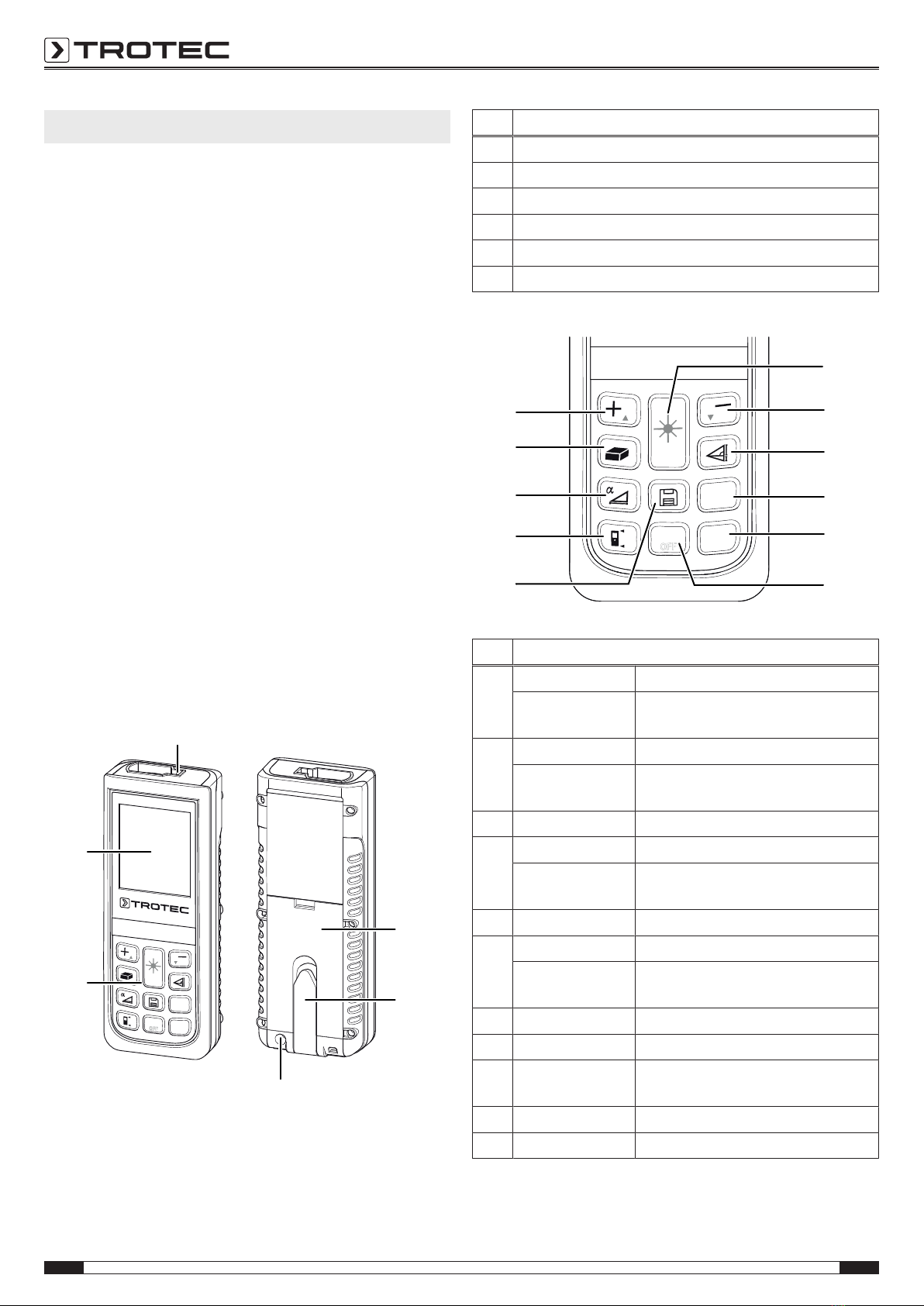
Device depiction
DIST
TIMER
Units
CLEAR
OFF
6
1
2
3
4
5
No. Designation
1 Battery compartment opening
2 Multifunctional end piece
3 Tripod thread
4 Operating elements
5 Display
6 Laser
Operating elements
DIST
TIMER
Units
CLEAR
OFF
7
8
9
10
11
12
13
14
15
16
17
No. Operating element
7 Press briefly: Switch-on/measurement button
Press for a long
time:
Button for permanent distance
measurements
8 Press briefly: Minus button
Press for a long
time:
Signal tone button (on/off)
9 Press briefly: Button for indirect measurements
10 Press briefly: Timer button
Press for a long
time:
Setting the timer
11 Press briefly: Unit button (ft, in, m)
12 Press briefly: Delete button
Press for a long
time:
Switch-off button
13 Press briefly: Save button (history)
14 Press briefly: Reference button
15 Press for a long
time:
Inclination button (on/off)
16 Press briefly: Area/room volume button
17 Press briefly: Plus button
EN 5
laser distance measuring device BD21 / BD26
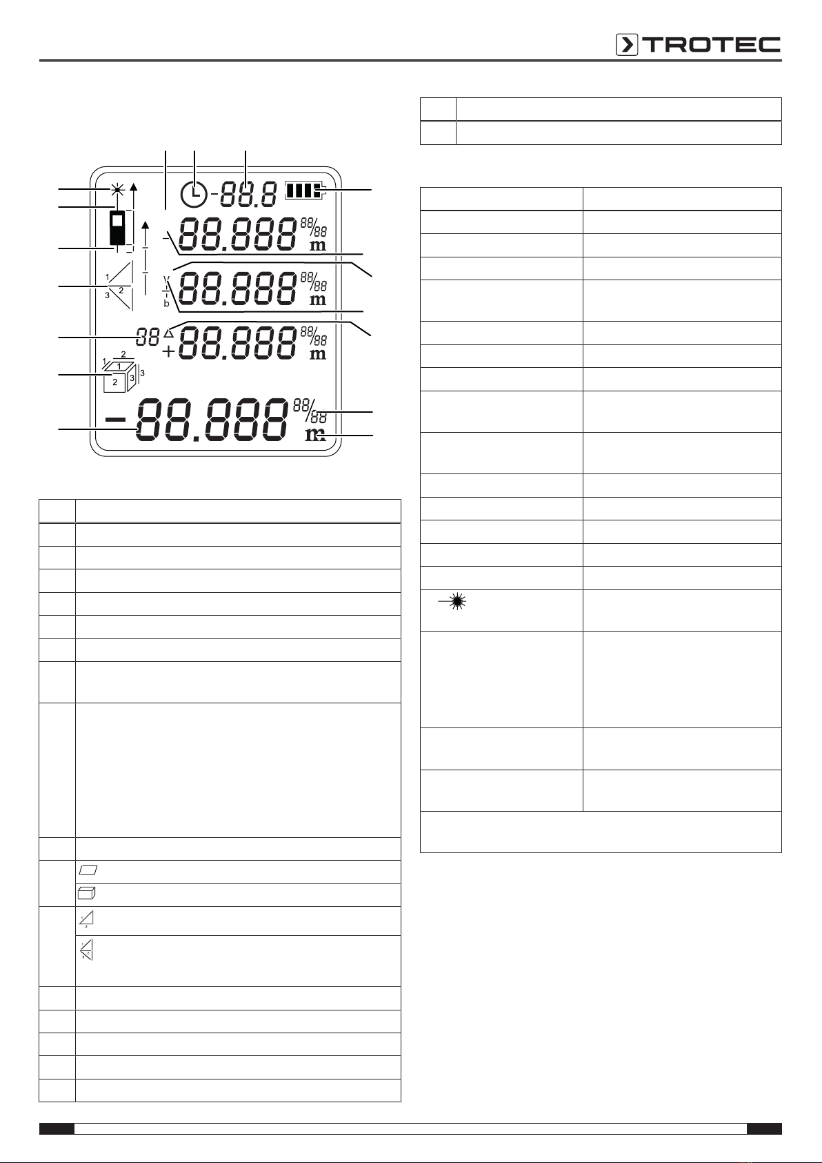
Display
max
min
H
a
a
b
b
18
19
20
21
22
23
24
25
27
26
28
29
30
31
32 33 34
No. Display element
18 Battery status
19 Horizontal measuring distance
20 Measured minimum value
21 Vertical measuring distance
22 Delta = maximum minus minimum
23 Complementary display when using imperial units
24 Display of the selected unit. Possible units are:
ft3, ft2, in, m, m3, m2
25 Measured value display:
The lower measurement value display indicates the last
measured value or the result of a calculation.
The three upper measurement value displays contain the
past three measured values, the minimum and
maximum value or the measured values to be added or
subtracted.
26 History and timer indication
27
Area measurement
Volume measurement
28 Indirect measurement (two auxiliary measurements)
Indirect measurement (three auxiliary
measurements)
29 Reference value rear
30 Reference value front
31 Laser active
32 Measured maximum value
33 Timer indication
No. Display element
34 Inclination angle indication
Technical data
Parameter Value
Model: BD21/ BD26
Weight: 150 g
Dimensions (Hx Wx D): 118x 49x 27 mm
Measuring range: BD21: 0.05 to 70 m
BD26: 0.05 to 120 m
Accuracy: ±2 mm*
Measuring range resolution: 1 mm
Horizontal measuring range: ±90°
Horizontal measuring range
accuracy:
±0.3°
Number of recordings
logged in the history:
10
Type of protection: IP54
Operating temperature: 0 °C to 40 °C
Storage temperature: -20 °C to 70 °C
Laser output: <1mW (620–690nm)
Laser class: II
Ø | m 6 mm / 30 mm / 60 mm |
10 m / 50 m / 100 m
Power supply: 2x Alkaline LR6 AAA batteries,
1.5 V or NiMH 1.2V to 1.5 V
(rechargeable batteries)
battery life: approx. 5000 to
8000measurements
Automatic switch-off of the
device:
After approx. 3minutes of
non-use
Automatic switch-off of the
laser:
After approx. 30seconds of
non-use
*under favourable conditions (good target surface, room
temperature) up to 10 m
Scope of delivery
• 1 x Laser distance measuring device
• 2x Alkaline LR6 AAA, 1.5 V battery
• 1x Device bag
• 1 x Wrist strap
• 1 x Quick guide
6 EN
laser distance measuring device BD21 / BD26
Transport and storage
Note
If you store or transport the device improperly, the
device may be damaged.
Note the information regarding transport and storage of
the device.
Transport
Use the supplied device bag (37) to transport the device.
Storage
When the device is not being used, observe the following
storage conditions:
• dry and protected from frost and heat
• protected from dust and direct sunlight
• The storage temperature is the same as the range given in
the Technical data chapter.
• Remove the batteries from the device.
• Preferably use the supplied device bag to store the device.
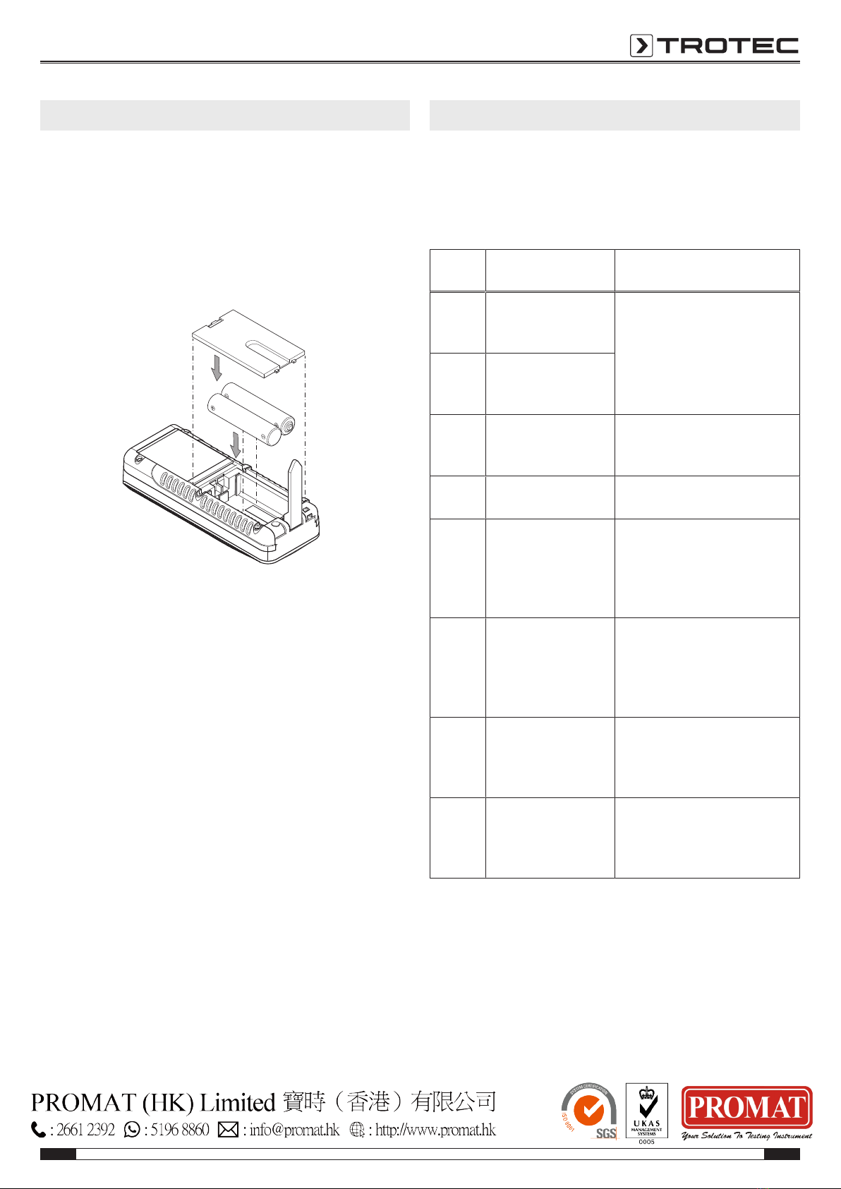
Operation
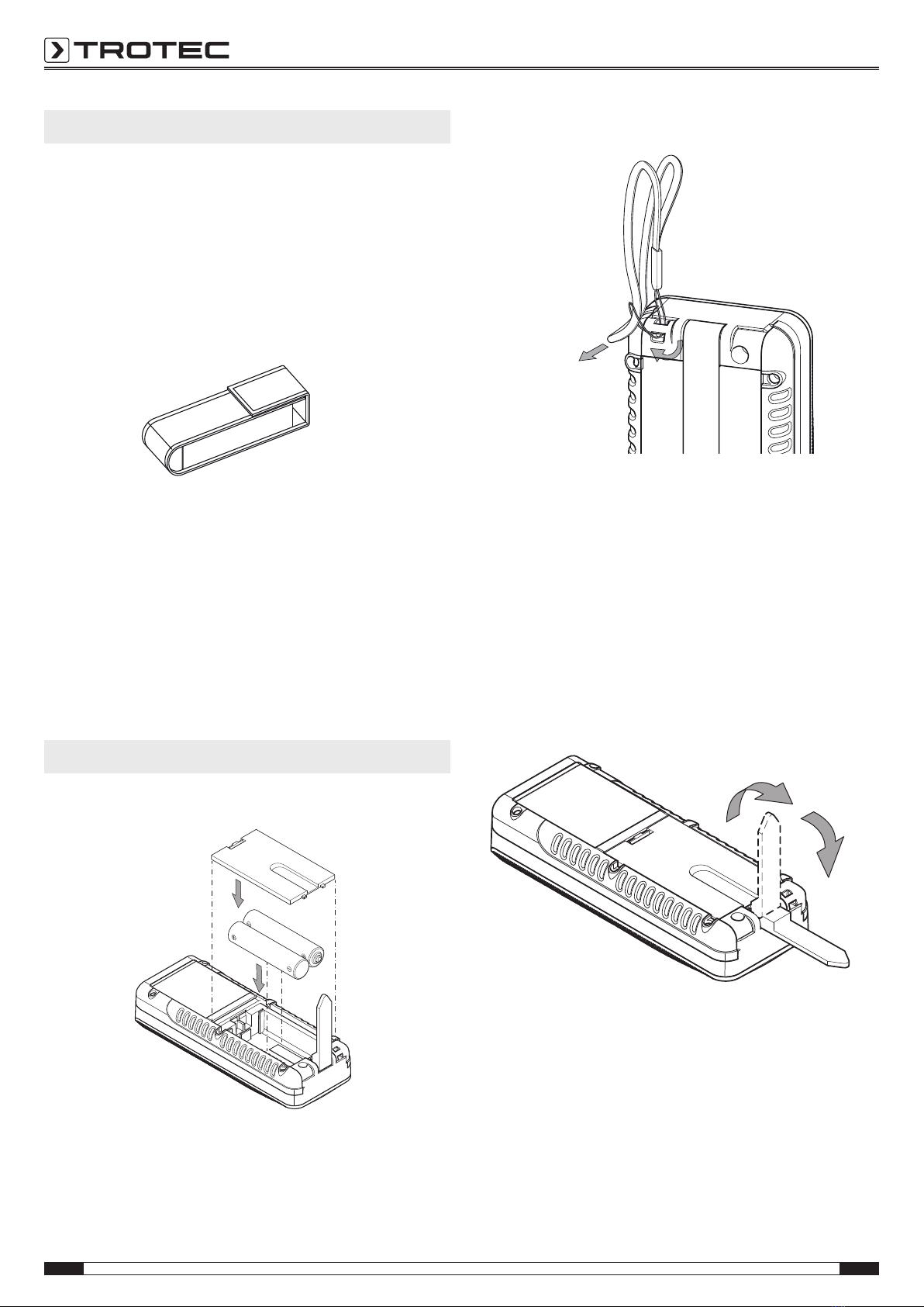
Inserting the batteries
Attaching the wrist strap
Switch-on
1. Briefly press the Switch-on/measurement button(7).
ðThe display will be switched on and the device ready for
operation.
Switch-off
1. Press the Switch-off button(12) for a long time.
ðThe display is switched off.
Using the multifunctional end piece
The device is equipped with a multifunctional end piece(2),
which you can use e.g. for measurements at corners. It serves
for device stabilization.
1. Fold out the end piece.
ðBD21: The position of the end piece and the associated
reference point must be set manually by pressing the
button(14).
ðBD26: The position of the end piece and the associated
reference point are automatically recognized by the
device.
ðAn extended depiction of the reference value rear(29)
indication is displayed.

EN 7
laser distance measuring device BD21 / BD26
Basic settings
Switching the acoustic signal on/off
1. Press the Minus button(8) for a long time to switch the
acoustic signal on or off.
ðThe switch-on/off process is confirmed by a brief
acoustic signal.
Aborting the measurement and deleting the display
1. Briefly press the Delete button(12) to abort the current
measurement or to delete the displayed measured values
one at a time.
Setting the reference value
The device always measures the total distance starting at the
reference point. This means that if the rear end of the device is
set as reference point, the length of the device will be part of
the measurement. By default the reference point is set to the
rear of the device. You can, however, also relocate the
reference point to the front part of the device. Please proceed as
follows:
1. Press the Reference button(14) to relocate the reference
point to the front end of the device.
ðAn acoustic signal is emitted each time the reference
point is relocated. Additionally, the indication Reference
value front(30) appears.
When switching the device off and then on again, the reference
value will automatically be relocated to the rear end of the
device.
Changing the units
1. Briefly press the Unit button(11) to switch between the
units for the measured values. Available units are m,
ft in,in and ft.
Info
If no measurement has been performed yet and if you
want to switch to another unit, there will be no unit
indication at first if you select ft in. Only if a
measurement is performed or if measured values are
already available will the measured values be
displayed in the xx' yy'' format.
Displaying the inclination
1. Briefly press the Inclination button(15).
ðThe inclination of the device will be indicated in the
Inclination display(34).
Calling up a measured value in the device history
The device automatically saves the last 10measured values.
The saved measured values can be called up as follows:
1. Press the Save button(13) to call up the history.
2. Briefly press the Minus button(8) or the Plus button(17) to
navigate through the history and call up the saved
measured values.
3. You can return to the normal measuring menu by briefly
pressing the Delete button(12) or the Measurement
button(7).
Setting the timer
The device is provided with an internal timer, which can be used
to set a delay after which the measurement begins. The timer
can be used for all measuring operations.
•Briefly press the Timer button(10) to activate a delay of
5 seconds.
• Press and hold the Timer button(10) until the desired time
is displayed (30 seconds max.).
• Let go of the Timer button(10) to start the timer.
– The Timer indication(33) and a countdown(26)
indicating the remaining seconds will appear on the
display.
– The last five seconds are each accompanied by an
acoustic signal.
– After the expiration of this time the measurement is
performed.
Carrying out measurements
Warning of laser radiation
Laser class2, Pmax.: <1mW, λ: 400-700nm,
EN60825-1:2014
Do not look directly into the laser beam or the opening
from which it emerges.
Never point the laser beam at people, animals or
reflective surfaces. Even brief eye contact can lead to
eye damage.
Examining the laser output aperture by use of optical
instruments (e.g. magnifying glass, magnifiers and the
like) entails the risk of eye damage.
When working with a laser of class2, observe the
national regulations on wearing eye protection.

8 EN
laser distance measuring device BD21 / BD26
Carrying out single distance measurement
1. Briefly press the Switch-on/measurement button(7) to
activate the laser.
2. Point the laser at the target area.
3. Briefly press the Switch-on/measurement button(7) again
to perform a distance measurement.
ðThe measured value is immediately indicated on the
display.
Adding/ subtracting measured values
1. Carry out a single distance measurement.
2. Press the Plus button(17) to add the next measured value
to the previous one.
Press the Minus button(8) to subtract the next measured
value from the previous one.
3. Press the Switch-on/measurement button(7) to determine
the next measured value.
ðThe overall result will be indicated in the lower
measurement value display. The individual measured
values will be indicated in the upper measurement value
displays.
Performing an area measurement
1. Briefly press the Area/room volume button(16) one time.
ðThe symbol
for area measurement appears on the
display.
2. Briefly press the Switch-on/measurement button(7) to
carry out the first measurement (e.g.length).
3. Briefly press the Switch-on/measurement button(7) again
to carry out the second measurement (e.g.width).
ðUpon pressing the Switch-on/measurement button(7)
for the second time the device independently calculates
the area and displays this value in the lower
measurement value display. The most recently
measured value will be indicated in one of the upper
measurement value displays.
Performing a volume measurement
1. Briefly press the Area/room volume button(16) twice.
ðThe symbol
for volume measurement appears on
the display.
ðThe side to be measured in each case is indicated on
the display by flashing.
2. Briefly press the Switch-on/measurement button(7) to
carry out the first measurement (e.g.length).
3. Briefly press the Switch-on/measurement button(7) again
to carry out the second measurement (e.g.width).
4. Briefly press the Switch-on/measurement button(7) again
to carry out the third measurement (e.g.height).
ðUpon pressing the Switch-on/measurement button(7) for
the third time the device independently calculates the
volume and displays this value in the lower measurement
value display.
Performing a non-stop/ min and max measurement
Use the non-stop measuring function to correlate
measurements e.g. with construction drawings. With this
measurement method the device can be moved closer toward
the target with the measured value being recalculated roughly
every 0.5seconds. The corresponding maximum and minimum
measured values are displayed in the first and second line
respectively.
For instance, you can direct the laser beam at a wall and then
retreat from it step by step. Keep reading the measured values
until the desired distance is achieved.
1. Press the Switch-on/measurement button(7) for a long
time until an acoustic signal can be heard.
2. With reference to the target point, move the device slowly
back and forth as well as up and down (e.g.in a corner).
3. Briefly press the Switch-on/measurement button(7) to
terminate the non-stop measurement.
ðThe maximum and minimum measured values and the
difference(Δ) between these two are indicated on the
display. Additionally, the last measured value will be
displayed in the bottommost line.

EN 9
laser distance measuring device BD21 / BD26
Indirect height measurement (Pythagoras)
Using this method the length of an unknown straight-line
segment can be determined via the Pythagorean Theorem. This
method is suitable for e.g. height measurements.
The measurement result is calculated by determining the
distance A and the inclination angle (standard setting) or by
determining the distances A and B.
A
B
Measurement with distance A and inclination angle:
1. Briefly press the Button for indirect measurements(9) one
time.
ðThe symbol for indirect measurements appears on
the display.
ðThe inclination angle is displayed in the third line of the
upper measurement value display on the right-hand
side (see example 33.0°).
ðThe bar with number 1 (hypotenuse) flashes.
H
29
25
28
2. Aim the device at the highest point(A) and briefly press the
Switch-on/measurement button(7) once to perform a
measurement. Make sure to hold the device as steady as
possible and place it level on the ground with the two rear
edges. The position at the two rear edges must not be
changed during the measurements!
ðBoth measurement and calculation are effected.
ðThe horizontal (1st line) and vertical (2nd line) distance
values are indicated in the upper measurement value
display.
ðThe line segment to be determined is displayed as
result in the lower measurement value display(25).
Measurement with distances A and B:
1. Briefly press the Button for indirect measurements(9) one
time.
ðThe symbol for indirect measurements appears on
the display.
ðThe bar with number 1 (hypotenuse) flashes.
2. Press the Inclination button(15) for a long time.
ðThere will be no angle displayed.
29
25
28
3. First, aim the device at the highest point(A) and briefly
press the Switch-on/measurement button(7) once to
perform a measurement. Make sure to hold the device as
steady as possible and place it level on the ground with the
two rear edges. The position at the two rear edges must
not be changed during the measurements!
ðThe length of the line segment will be indicated in the
1stline of the upper measurement value display.
4. Align the device horizontally (point B) and briefly press the
Switch-on/measurement button(7) one time to measure
the horizontal distance.
ðThe second measured value will be indicated in the
second line of the upper measurement value display.
ðThe line segment to be determined is displayed as
result in the lower measurement value display(25).
10 EN
laser distance measuring device BD21 / BD26
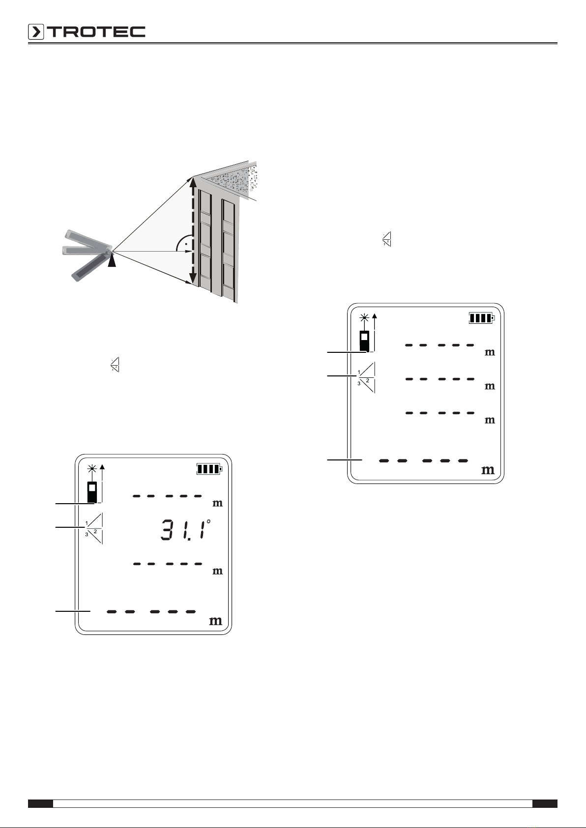
Twofold indirect height measurement
This method is suitable for e.g. height measurements.
The measurement result is calculated by determining the
distances A and C as well as the inclination angle (standard
setting) or by determining the distances A, B and C.
A
B
C
Measurement with distances A, C and inclination angle:
1. Briefly press the Button for indirect measurements(9)
twice.
ðThe symbol for indirect measurements appears on
the display.
ðThe inclination angle is displayed in the second line of
the upper measurement value display on the right-hand
side (see example 31.1°).
ðThe bar with number 1 (hypotenuse) flashes.
29
25
28
2. First, aim the device at the highest point(C) and briefly
press the Switch-on/measurement button(7) once to
perform a measurement. In doing so, hold the device as
steady as possible. The alignment of the device in
relation to the reference point must not be changed
during the measurements!
ðThe first measured value will be displayed in the upper
measurement value display.
3. Aim the device at the lowest point(A) and briefly press the
Switch-on/measurement button(7) once to perform a
measurement.
ðThe second measured value will be indicated in the
third line of the upper measurement value display.
ðThe angle will be indicated in the second line of the
upper measurement value display.
ðThe line segment to be determined is displayed as
result in the lower measurement value display(25).
Measurement with distances A, B and C:
1. Briefly press the Button for indirect measurements(9)
twice.
ðThe symbol for indirect measurements appears on
the display.
2. Press the Inclination button(15) for a long time.
ðThere will be no angle displayed.
29
25
28
3. First, aim the device at the highest point(C) and briefly
press the Switch-on/measurement button(7) once to
perform a measurement. In doing so, hold the device as
steady as possible. The alignment of the device in
relation to the reference point must not be changed
during the measurements!
ðThe first measured value will be displayed in the upper
measurement value display.
4. Align the device horizontally (point B) and briefly press the
Switch-on/measurement button(7) one time to measure
the horizontal distance.
ðThe second measured value will be indicated in the
second line of the upper measurement value display.
5. Aim the device at the lowest point(A) and briefly press the
Switch-on/measurement button(7) once to perform a
measurement.
ðThe third measured value will be indicated in the third
line of the upper measurement value display.
ðThe line segment to be determined is displayed as result in
the lower measurement value display(25).
EN 11
laser distance measuring device BD21 / BD26
Maintenance and repair
Battery change
Note
Make sure that the surface of the device is dry and the
device is switched off.
A battery change is required when the error message INFO203
appears on the display or when the device can no longer be
switched on (see chapter Inserting the batteries).
Cleaning
Clean the device with a soft, damp and lint-free cloth. Make
sure that no moisture enters the housing. Do not use any
sprays, solvents, alcohol-based cleaning agents or abrasive
cleaners, but only clean water to moisten the cloth.
Repair
Do not modify the device or install any spare parts. For repairs
or device testing, contact the manufacturer.
Errors and faults
The device has been checked for proper functioning several
times during production. If malfunctions occur nonetheless,
check the device according to the following list.
The following fault indications can appear in the lower
measurement value display together with the word INFO:
Indicati
on
Cause Remedy
101 The reception of the
reflected signal is too
weak.
Repeat measurement on
another surface with better
reflective properties or use a
target plate.
102 The reception of the
reflected signal is too
strong.
201 The ambient light is
too intense.
Change the ambient light
conditions for the
measurement.
203 The batteries are
almost empty.
Change the batteries, see
chapter Battery change.
301 The temperature is
too high.
Allow the device to cool down.
Observe the permissible
operating temperature
according to the Technical data
chapter.
302 The temperature is
too low.
Allow the device to warm up.
Observe the permissible
operating temperature
according to the Technical data
chapter.
401 Hardware fault Repeatedly switch the device
on and off. If the symbol does
not disappear, please contact
your retailer.
402 Calculation error Repeat the measurement. Pay
attention to the measurement
sequence and position of the
device.
This manual suits for next models
1
Table of contents
Other PROMAT Measuring Instrument manuals


