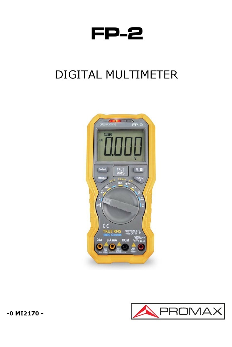
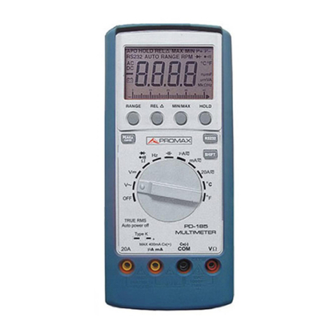
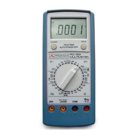
Promax FP-2b User manual


SAFETY NOTES
Read the instruction manual before using the equipment, mainly
"SAFETY RULES" paragraph.
The symbol on the equipment means "SEE INSTRUCTION
MANUAL". In this manual may also appear as a Caution or
Warning symbol.
"WARNING AND CAUTION" statements may appear in this
manual to avoid injury hazard or damage to this product or other
property.


TABLE OF CONTENTS
1 GENERAL CHARACTERISTICS ............................................ 1
2 SPECIFICATIONS.................................................................. 3
3 SAFETY RULES..................................................................... 9
3.1 General safety rules ......................................................... 9
3.2 Specific safety rules........................................................ 10
4 OPERATING INSTRUCTIONS ............................................. 11
5 MAINTENANCE ................................................................... 13
5.1 Shipment instructions ..................................................... 13
5.2 Battery replacement ....................................................... 13
5.3 Replacing the fuse.......................................................... 14
5.4 Cleaning recommendations ............................................ 14


USER'S MANUAL FP-2b
Janvier 2001 Page 1
1 GENERAL CHARACTERISTICS
- Push-push power switch
- Big LCD of 22 mm with measuring units indication
- Rotary selector with 32 positions
- High sensibility up to 100 µV
- Automatic overrange indication by means of "1" on the display
- Automatic polarity indication on the DC range
- Resistance measurement from 0.1 Ω up to 200 MΩ
- Capacity measurement from 1 pF up to 20 µF
- Diode test
- Input overload protection
- Transistors test socket to directly measure the hFE parameter
- Quick audible continuity test by means of a buzzer
- Low battery indication on the LCD display

USER'S MANUAL FP-2b
Page 2 Janvier 2001

USER'S MANUAL FP-2b
Janvier 2001 Page 3
2 SPECIFICATIONS
Readout LCD 3 ½ digits
Reading update 2-3 measurements / s
Overrange indication "1" displayed only
Polarity indication "-" displayed automatically for
negative polarity.
Low battery indication appears on the display
Operating temperature 5 to 40 °C
Storage temperature -10 °C to 50 °C
Power supply 9V battery (6F22)
Dimensions W. 88 x H. 170 x D. 38 mm.
Weight 340 g. (battery included)
Included accessories Test leads PP-008
Case DC-231
NOTE: Accuracy is specified at 23 ± 5 °C and relative humidity
under 75%.
DC Voltage
Range Resolution Accuracy
200 mV 100 µV
2 V 1 mV
20 V 10 mV
200 V 100 mV
± (0.5% reading
+ 1 dig.)
1000 V 1 V ± (0.8% reading + 2 dig.)
Input impedance: 10 MΩ
Overload protection: 250 V rms in the 200 mV range
1000 V DC in the other ranges

USER'S MANUAL FP-2b
Page 4 Janvier 2001
AC Voltage
Range Resolution Accuracy
2 V 1 mV
20 V 10 mV
200 V 100 mV
± (0.8% reading
+ 3 dig.)
750 V 1 V ± (1.2% reading
+ 3 dig.)
Input impedance: 10 MΩ
Frequency range: 40 Hz to 1000 Hz
Overload protection: 700 V AC (sine wave signal)
Indication: Average, calibrated in RMS of sine wave
DC Current
Range Resolution Accuracy
2 mA 1 µA
20 mA 10 µA
± (0.8% reading
+ 1 dig.)
200 mA 100 µA± (1.5% reading + 1 dig.)
10 A 10 mA ± (2.0% reading + 5 dig.)
Overload protection: By fuse
(10 A range without protection)
Maximum input current: 10 A in continuous mode
20 A for 15 s. maximum

USER'S MANUAL FP-2b
Janvier 2001 Page 5
AC Current
Range Resolution Accuracy
20 mA 10 µA± (1% reading + 3 dig.)
200 mA 100 µA± (1.8% reading + 3 dig.)
10 A 1 mA ± (3% reading + 7 dig.)
Overload protection: By fuse
(10 A range without protection)
Frequency range: 40 Hz up to 400 Hz
Maximum input current: 10 A in continuous mode, 20 A, 15 s maximum
Response: Average, calibrated in rms of sine wave
Resistance
Range Resolution Accuracy
200 Ω0.1 Ω± (0.8% reading + 3 dig.)
2 kΩ1 Ω
20 kΩ10 Ω
200 kΩ100 Ω
2 MΩ1 kΩ
± (0.8% reading + 1 dig.)
20 MΩ10 kΩ± (1% reading + 2 dig.)
200 MΩ100 kΩ± (5% (reading –10 dig.) + 10 dig.)*
*On 200 MΩ range, if inputs are short circuited, display will read 10 digits
approximately (minimum resolution units). This reading should be
subtracted from the readout.
Overload protection: 250 V DC/AC rms

USER'S MANUAL FP-2b
Page 6 Janvier 2001
Capacity
Range Resolution Accuracy
2 nF 1 pF
20 nF 10 pF
200 nF 100 pF
2 µF1 nF
2 µF10 nF
± (4% reading + 3 dig.)
Frequency test
Range Resolution Accuracy
2 kHz 1 Hz ± (2% reading + 5 dig.)
20 kHz 10 Hz ± (1.5% reading + 5 dig.)
Overload protection: 250 V DC/AC rms
Sensitivity: 200 mV AC rms
Maximum input current: 10 V AC rms
Diode test
Range
Readout Approximate forward voltage drop
Overload protection 250 V DC/AC rms

USER'S MANUAL FP-2b
Janvier 2001 Page 7
Continuity test
Range
Threshold 50 Ω
Overload protection 250 V DC/AC rms
Transistors test
Range hFE
Readout hFE (DC gain)
Base current 10 µA
Vce voltage 3.2 V

USER'S MANUAL FP-2b
Page 8 Janvier 2001

USER'S MANUAL FP-2b
Janvier 2001 Page 9
3 SAFETY RULES
3.1 General safety rules
∗ This equipment can be used in Overvoltage Category II
installations and Pollution Degree 2 environments.
∗ Remember that voltages above 60 V DC or 30 V AC rms
may be dangerous.
∗ When using some of the following accessories use only the
specified ones to ensure safety:
Test leads
∗ Use this instrument under the specified environmental
conditions.
∗ The user is only authorized to carry out the following
maintenance operations:
Battery replacement
Fuse replacement, according to the indicated type and
value.
On the Maintenance paragraph the proper instructions are
given.
Any other change on the equipment should be carried out by
qualified personnel.
∗ Observe all specified ratings both of supply and
measurement.
∗ Follow the cleaning instructions described in the
Maintenance paragraph.

USER'S MANUAL FP-2b
Page 10 Janvier 2001
3.2 Specific safety rules
∗ When measuring resistances take care that circuit under test
is not powered.
∗ When measuring currents disconnect the power supply of the
circuit under test before inserting the multimeter in series.
∗ When measuring currents, be sure that points under test do
not exceed the maximum voltage.
∗ Keep measuring leads in good condition.
∗ Between measurements higher than 10 A which extend near
to the maximum time specified, keep waiting times of about
10 minutes.
∗ Before rotating the range selector, disconnect the test leads
from the circuit under test.
∗ When measuring capacities, be sure capacitors are
previously discharged.
∗ Disconnect the test leads before inserting transistors or
capacitors in their respective sockets.

USER'S MANUAL FP-2b
Janvier 2001 Page 11
4 OPERATING INSTRUCTIONS
Measuring voltage
Connect the test leads to the V/Ω/Hz jack (red) and the COM jack
(black). Select the desired range position (continuous or
alternating) and connect test leads across the source or load under
measurement.
Measuring current
Connect the black test lead to the COM jack and the red test lead
to the mA jack. Set the rotary selector at desired range (continuous
or alternating) and connect the test leads to the measurement
points. For currents higher than 200 mA, connect the test leads to
the 10 A (red) and COM (black) jacks.
Measuring resistance
Connect the black test lead to the COM jack and the read test lead
to the V-Ω-Hz jack, selecting the correct range.
Measuring capacities
Set the rotary selector in the suitable "Cx" position and take care of
polarity when measuring polarized capacitors.
Before carrying out the measurement, the capacitor under test
must be discharged.
CAUTION
Do not apply voltage to the capacitor socket since
important breakdown to the instrument could be
produced.
Insert the capacitor in the "Cx" socket and read the value in the
display.

USER'S MANUAL FP-2b
Page 12 Janvier 2001
Testing diodes and continuity test
Set the rotary selector at position. The test leads must be
connected to the V/Ω/Hz and COM jacks. Connecting the test
leads to the diode under test (black lead to the cathode and red
lead to the anode) the meter will show the approx. forward voltage
drop of the diode (between 500 and 900 mV for a silicon diode). If
the lead connection is reversed, only figure ''1'' will be displayed.
Set the rotary switch at position and connect the test leads
across two points of the circuit under testing. If continuity exists
(i.e, resistance less than about 50 Ω) built-in buzzer will sound.
Testing transistor
Set the rotary selector at hFE position and verify if transistor is PNP
or NPN type. Insert leads of the transistor to be tested into proper
holes. LCD display will show the approximate hFE value.
Measuring frequencies
Set the rotary selector at Hz position (2 k or 20 k). Connect the
black test lead to the "COM" jack and the red test lead to the
"V-Ω-Hz" jack. Connect the test leads to the measuring points and
red the frequency in the display.
Auto Power-off
The meter will be turned-off automatically within around 20
minutes. To turn on the meter again, push the power switch or turn
the rotary selector

USER'S MANUAL FP-2b
Janvier 2001 Page 13
5 MAINTENANCE
5.1 Shipment instructions
Instruments sent to repair or to calibrate, inside or outside the
warranty period, must enclose the following information: Company
name, name of the person to contact if necessary, address,
telephone number, purchase receipt (in the case of warranty
period), and problem description. Freights will be charged to the
client.
5.2 Battery replacement
- When the symbol appears on the LCD display, it
indicates that the battery should be replaced.
- After disconnecting the test leads and setting the rotary
selector at the OFF position, remove screws on the back
cover and open the case.
- Replace the exhausted battery with a new one.
- Set the cover again and fix the rear screws.

USER'S MANUAL FP-2b
Page 14 Janvier 2001
5.3 Replacing the fuse
- Disconnect the test leads and turn off the multimeter, remove
screws on the back cover and open the case.
- Check if the fuse is melt, if necessary replace it with a new one
of the following characteristics:
200 mA, F, 250 V
- Place and fix the lid again.
5.4 Cleaning recommendations
The cover should be cleaned by means of a light solution of
detergent and water applied with a soft cloth.
Dry thoroughly before using the system again.
CAUTION
Do not use scented hydrocarbons or chlorized
solvents. Such products may attack the plastics used
in the construction of the cover.
Table of contents
Other Promax Multimeter manuals