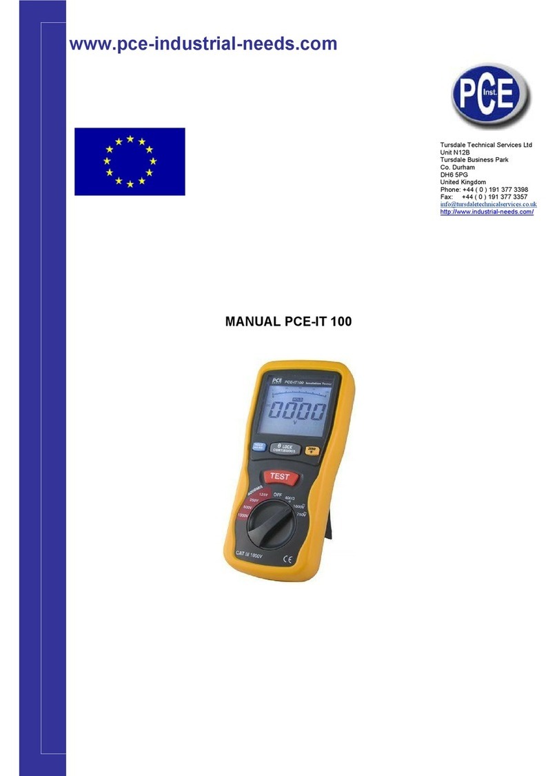
PCE Instruments PCE-IT 100 User manual

www.pce-industrial-needs.com
Tursdale Technical Services Ltd
Unit N12B
Tursdale Business Park
Co. Durham
DH6 5PG
United Kingdom
Phone: +44 ( 0 ) 191 377 3398
Fax: +44 ( 0 ) 191 377 3357
info@tursdaletechnicalservices.co.uk
http://www.industrial-needs.com/
MANUAL PCE-IT 100
All manuals and user guides at all-guides.com
all-guides.com

info@tursdaletechnicalservices.co.uk
2
Safety symbols:................................................................................................................................................ 3
1.SPECIFICATIONS........................................................................................................................................... 4
1.1General Information Environment conditions: ........................................................................................... 4
Maintenance & Clearing:.......................................................................................................................... 4
Display: Large LCD with dual display...................................................................................................... 4
Measurement Range ................................................................................................................................ 4
Sampling Rate ........................................................................................................................................... 4
Zero Adjustment: ....................................................................................................................................... 4
Over Range Indicator................................................................................................................................ 4
Low Battery Indication: ............................................................................................................................. 4
Operating Temperature............................................................................................................................ 4
Storage Temperature................................................................................................................................ 4
Power source ............................................................................................................................................. 4
Dimensions:................................................................................................................................................ 4
Weight ......................................................................................................................................................... 4
Accessories................................................................................................................................................ 4
1.2 Electrical Specifications............................................................................................................................. 5
OHMS.......................................................................................................................................................... 5
Continuity Beeper...................................................................................................................................... 5
DC Voltage ................................................................................................................................................. 5
AC Voltage (40Hz~400Hz) ...................................................................................................................... 5
Meg OHMS................................................................................................................................................. 5
2. PARTS & CONTROLS................................................................................................................................... 6
2-1 How to connect test leads. ......................................................................................................................... 6
2-2 Battery Check-UP & Replacement............................................................................................................ 6
2-3 Test leads check......................................................................................................................................... 6
2-4 Rotary Switch positions............................................................................................................................. 6
2-5 Buttons and a display Indicators................................................................................................................ 7
a). Button...................................................................................................................................................... 7
b).Display Indicators ................................................................................................................................ 7
3. INSULATION RESISTANCE MEASUREMENTS ...................................................................................... 8
4.LOW RESISTANCE (CONTINUITY) MEASUREMENTS .......................................................................... 8
5.AC/DC VOLTAGE MEASUREMENTS......................................................................................................... 8
6.BATTERY SAVER (SLEEP MODE).............................................................................................................. 9
7.POWER TOOLS AND AMALL APPLIANCES............................................................................................. 9
MOTORS......................................................................................................................................................... 9

CABLES .......................................................................................................................................................... 9
All manuals and user guides at all-guides.com

info@tursdaletechnicalservices.co.uk
3
SAFETY INFORMATION
zRead the following safety information carefully before attempting to operate or service the meter.
zTo avoid damages to the instrument do not apply the signals which exceed the maximum limits shown in
the technical specifications tables.
zDo not use the meter or test leads if they look damaged. Use extreme caution when working around bare
conductors or bus bars.
zAccidental contact with the conductor could result in electric shock.
zUse the meter only as specified in this manual; otherwise, the protection provided by the meter may be
impaired.
zRead the operating instructions before use and follow all safety Information.
zCaution when working with voltages above 60V DC or 30V AC RMS. Such voltages pose a shock
hazard.
zBefore taking resistance measurements or testing acoustic continuity, disconnect circuit from main
power supply and all loads from the circuit.
Safety symbols:
Caution refer to this manual before using the meter.
Dangerous voltages.
Meter is protected throughout by double insulation or reinforced insulation.
When servicing, use only specified replacement parts.
CE Comply with EN-61010-1
All manuals and user guides at all-guides.com

info@tursdaletechnicalservices.co.uk
4
1.SPECIFICATIONS
1.1General Information Environment conditions:
①Installation Categories
②Pollution Degree 2
③Altitude up to 2000 meters
④Indoor use only
⑤Relatively humidity 80% max.
⑥Operation Ambient 0~40ºC
Maintenance & Clearing:
①Repairs or servicing not covered in this manual should only be performed by qualified personnel.
②Periodically wipe the case with a dry cloth. Do not use abrasives or solvents on this instruments.
Display: Large LCD with dual display
Measurement Range: 4000MΩ/125V, 4000MΩ/250V, 4000MΩ/500V, 4000MΩ/1000V, 400Ω/BZ,
1000V/DCV. ,750V/ACV
Sampling Rate: 2.5 times per second.
Zero Adjustment: Automatic adjustment.
Over Range Indicator: “OL” of highest digit is displayed.
Low Battery Indication: The is displayed when the battery Voltage drop below the operating voltage.
Operating Temperature: 0ºC to 40ºC (32ºF to 104ºF) and Humidity below 80% RH
Storage Temperature: -10ºC to 60ºC (14ºF to 140ºF) and Humidity below 70% RH
Power source: DC9V (6x1.5V Size “AA” battery or Equivalent)
Dimensions: 200(L) x 92(W) x 50(H) mm
Weight: Approx 700g include battery
Accessories: Test leads, 6pcs battery, Carrying case, manual.
All manuals and user guides at all-guides.com

info@tursdaletechnicalservices.co.uk
5
1.2 Electrical Specifications
Accuracies are specified in the way:
±(…% of reading +…digits) at 23ºC±5ºC,below 80% RH.
OHMS
Range Resolution
A
ccuracy Max. open
Circuit Voltage
Overload
Protection
40.00Ω0.01Ω+(1.2%+3) 5.8V 250Vrms
400.0Ω0.1Ω5.8V
Continuity Beeper
Range Resolution Operation
Resistance
Max.open Circuit
Voltage
Overload
Protection
•))) 0.01ΩResistance≤35Ω5.8V 250Vrms
Short circuit current ≧200mA
DC Voltage
Range Resolution
A
ccuracy Input Impedance Overload
Protection
1000V 1V +(0.8%+3) 10MΩ1000Vrms
AC Voltage (40Hz~400Hz)
Range Resolution
A
ccuracy Input Impedance Overload
Protection
750V 1V +(1.2%+10) 10MΩ750Vrms
Meg OHMS
Terminal
Voltage
Range Resolution
A
ccuracy Test Current Short circuit
current
125V(0%~+1
0%)
0.125~4.000 MΩ0.001MΩ+(2%+10) 1mA
@load125kΩ
≤1mA
4.001~40.00 MΩ0.01MΩ+(2%+10)
40.01~400.0 MΩ0.1MΩ+(4%+5)
400.1~4000 MΩ1MΩ+(5%+5)
250V
(0%~+10%)
0.250~4.000 MΩ0.001MΩ+(2%+10) 1mA
@load250kΩ
≤1mA
4.001~40.00 MΩ0.01MΩ+(2%+10)
40.01~400.0 MΩ0.1MΩ+(3%+5)
400.1~4000 MΩ1MΩ+(4%+5)
500V(0%~+1
0%)
0.500~4.000 MΩ0.001MΩ+(2%+10) 1mA
@load500kΩ
≤1mA
4.001~40.00 MΩ0.01MΩ+(2%+10)
40.01~400.0 MΩ0.1MΩ+(2%+5)
400.1~4000 MΩ1MΩ+(4%+5)
1000V
(0%~+10%)
1.000~4.000 MΩ0.001MΩ+(3%+10) 1mA
@load1MΩ
≤1mA
4.001~40.00 MΩ0.01MΩ+(2%+10)
40.01~400.0 MΩ0.1MΩ+(2%+5)
400.1~4000 MΩ1MΩ+(4%+5)
All manuals and user guides at all-guides.com

info@tursdaletechnicalservices.co.uk
6
2. PARTS & CONTROLS
1.Digital Display
2.Data Hold Button; MAX/MIN
3.Lock Button
4.Backlight Button; ZERO
5.Test Button
6.Rotary Function switch
7.VΩJack
8.COM input jack
9. Pothook
10.Battery Cover
2-1 How to connect test leads.
On MΩRange , and 400Ω/BZ ,ACV,.DCV, Connect the red test lead into the “VΩ” terminal and the black
lead into the “COM” terminal.
2-2 Battery Check-UP & Replacement
a) As battery power is not sufficient. LCD will display . Replacement of 6 pcs new batteries, type 1.5V
size “AA” is Required.
b). Place back the battery cover and four the screws.
2-3 Test leads check
Set the range select switch to the 400Ωrange. With the tip and alligator clip of the test leads connected. The
indicator should read 00.0Ω. When the leads are not connected the display will read infinity indicated by
“OL”. This will ensure that test lead are under working condition.
2-4 Rotary Switch positions
Turn the Tester on by selecting any measurement
Lift <1000v,500v,250v,125v (4000MΩ)
OFF 400Ω/BZ, 1000VDC,750VAC >Right
750V
1000V
Insulation Tester
400
125V
250V
500V
1000V
TEST
LOBAT HV
(1)
POL1
(2)
(1)
OHM
BZ
(2)
(2)
POL2
4
(1)
BAR
1
8 5
1
2
3
4
6
78
9
10
CEM DT-5505
5
All manuals and user guides at all-guides.com
all-guides.com

2-5
B
a).
HOL
D
prim
a
“MA
X
recyc
LOC
K
TES
T
butto
n
TES
T
bring
the hi
ZER
O
displ
a
press
seco
n
b)
.
The
P
DCV
w
the c
u
“
“
“•)
LO
C
MA
X
ZE
R
HO
L
AC,
V,M
Bu
ttons
Button
D
/MAX.MI
N
a
ry display.,
X
” status, a
n
le ,but exit
i
K
: In the i
T
” key, it wil
n
once mor
e
T
: In the i
n
high-volta
g
gh-voltage
O
/LIGHT
:
a
y will be s
ing for 2 s
e
n
ds, the ba
c
.
Display I
n
P
rimary Dis
p
w
hile you t
e
u
rrent funct
i
“
“:While t
e
“ flashes
f
))” :While t
e
continua
BZ warn
s
C
K
: Push
d
indicat
e
X
/MIN
: Sta
R
O
: Digita
L
D
: The
d
DC
: The i
n
Ω,Ω
: The
m
and a d
is
N
: Instan
but it will r
e
n
d one ano
t
i
f pressing
2
nsulation r
e
l occur the
e
,it will sh
u
n
sulation re
s
g
e, and ent
e
and exit fo
r
Iinstant-pr
e
et zero,(m
a
e
conds, it
w
c
klight is sh
n
dicators
p
lay: Indic
a
e
st the ins
u
i
on testing
v
e
sting the i
n
f
requently i
f
e
sting the
i
lly if the o
u
s
continuo
u
d
own the “
L
e
d. LOBAT
T
nd for the
m
l zero adju
s
d
igital holdi
n
n
dicator for
t
m
easured
d
is
play In
d
t-pressing
t
e
turn in the
t
her instan
t
2
seconds
a
e
sistance t
e
high-volta
g
u
toff the hig
s
istance te
s
e
r into the
i
r
m the insu
l
e
ssing the
“
a
inly used
f
w
ill enter di
r
ut off auto
m
a
te the curr
e
u
lation resis
v
alue in sy
n
n
sulation re
f
the voltag
e
i
nsulation r
e
u
tside volta
g
u
sly.
L
OCK” butt
o
T
he displa
y
m
aximum o
r
s
ting
n
g function
t
he voltage
d
imension
u
d
icators
t
he “HOLD
”
2nd pressi
n
t
-pressing
w
a
gain.
e
sting func
t
g
e and ent
e
h-voltage a
s
ting functi
o
i
nsulation r
e
l
ation resis
t
“
ZERO/LIG
H
f
or 400Ω, t
h
r
ectly into t
h
m
atically, th
e
nt function
tance, and
n
chronous
w
sistance, t
h
e
is over 3
0
e
sistance,
t
g
e is over 3
o
n while y
o
y
shows “L
O
r
the minim
for the pri
m
property.
u
nits
”
button th
e
n
g ; pressi
n
w
ill switch t
o
t
ion ,press
e
r the insul
a
nd exit fro
m
o
n ,pressin
g
e
sistance t
e
t
ance testin
H
T” button
h
e low resi
h
e “LIGHT”
e same as
testing val
u
the battery
w
ith the pri
m
h
e symbol
0
V.
t
he symbol
0V. the sy
m
o
u test the
O
BAT” whe
n
um.
m
ary displa
y
e
1st time,
t
n
g 2 secon
d
o
the “MIN”
the “LOC
K
a
tion resist
a
m
the insula
g
and holdi
e
sting, bei
n
g.
in the 1st t
i
stance tes
t
status, an
d
pressing fo
u
es The S
e
voltage w
h
m
ary displa
y
” •))) “ flas
h
m
bol “ •))) “
insulation
r
n
the volta
g
y
.
t
he current
d
s ,it will en
t
, if instant-
p
K
” button ,
a
a
nce testin
g
tion resista
ng the “TE
S
n
g free fro
m
i
me, the cu
r
t
ing), ,it wil
l
d
the LCD
b
r 2 second
s
e
condary Di
h
ile the AC
V
y
.
h
es freque
n
is indicate
d
r
esistance
a
g
e drops be
info@tursdale
values wil
l
t
er directly
p
ressing o
n
a
nd then p
u
g
status. Pr
e
nce testing
S
T” button,
m
the “TES
T
rrent value
s
l
return if i
n
b
acklight li
g
s
within 15
s
splay : It s
h
V
The Anal
o
n
tly and th
e
d
while LO
a
nd the sy
m
low 7.5V
t
echnicalservice
s
l
be hold i
n
into the
n
ce more, i
t
u
sh down t
e
ss the “T
E
status.
The mete
r
T
” , it will c
u
s
in the pri
m
n
the 2nd t
g
ht up. Aft
e
s
.
h
ows the o
u
o
g Bar: indi
c
e
buzzer w
a
Ω≤35Ωan
d
m
bol “
s
.co.uk
7
n
the
t
will
he “
E
ST”
r
will
u
toff
m
ary
ime.
e
r 15
u
tput
c
ate
a
rns
d
the
” is
All manuals and user guides at all-guides.com

3. I
N
a)Tur
M
Ω
M
Ω
b)Co
n
c)Pu
s
the
tes
t
fre
q
pro
ph
a
sy
m
d)Bei
the
pri
m
vol
t
e)Su
b
Tur
n
4.L
O
a). S
e
b). C
o
c). C
o
T
h
fl
a
d). W
e) Th
e
f) Th
e
fre
q
5.A
C
a). S
e
b). C
o
c). C
o
d). R
e
N
SULA
T
n the func
t
Ω
/250V---10
Ω
400 MΩ40
0
n
nect two t
e
s
h down an
tested is
e
t
ing occurs
,
q
uently. if t
h
cess and b
a
se with an
m
bol “ ” fl
a
ng free fro
m
“LOCK” s
t
m
ary displa
t
age for the
b
sequently,
n
ing the fun
O
W RE
S
e
t the rang
e
o
nnect the
r
o
nnect the
t
h
e two rang
e
a
shes in sy
n
hen the im
p
e
current is
e
high volt
a
q
uently if th
e
C
/DC V
O
e
t the rang
e
o
nnect red
t
o
nnect test
e
ad the vol
t
T
ION R
E
t
ion switch
00 MΩ/12
5
0
0 MΩ, ca
n
e
sting lines
d hold the
“
e
lectriferou
s
,
simultane
i
h
e tested is
rings the hi
alog bar; o
a
shes and t
m
the “TES
T
t
atus and s
y will be h
e
tested.
discharge
t
ction switc
h
S
ISTAN
e
switch to
4
r
ed test lea
d
t
ips of the
t
e
s(40.00/40
0
n
chronous
w
p
edance o
n
from 200 t
o
a
ge symb
o
e
voltage (
A
O
LTAG
E
e
switch to
A
t
est lead to
prods of te
s
t
age value
o
E
SISTA
from the
“
5
V),and c
h
n
be switch
e
to the test
e
“
TEST” but
t
s
and its v
o
i
ty, it show
s
diselectrif
e
gh-voltage.
n the seco
n
he buzzer
w
T
” button o
hutoff the
h
e
ld, and th
e
t
he balanc
e
h
can exit a
u
CE (C
O
4
00Ω/BZ P
o
d
to the V
Ω
t
est leads t
o
0
.0Ω) can
b
w
ith the an
a
n
circuit is b
o
220mA w
o
l “ “ fla
A
C/DC) is
m
E
MEA
S
A
CV or DC
V
“V Ω” term
i
s
t leads IN
P
o
n LCD.
NCE M
E
“
OFF” posi
h
ose one
o
e
d automati
e
d;
t
on /or pre
s
o
ltage ( A
C
s
“>30V” o
n
e
rous or its
v
on the pri
m
n
dary displ
a
w
arns freq
u
r pushing
d
h
igh-voltag
e
e
seconda
r
e
insulation
u
tomaticall
y
O
NTINU
I
o
sition
Ω
terminal
a
o
both end
s
b
e switche
d
a
log bar.
elow appro
x
hile the tes
t
shes alon
g
m
ore than 3
S
UREM
V
position
i
nal and bl
a
P
ARALLE
L
E
ASUR
tion to the
o
f the volt
a
cally for ev
e
s
s the “ LO
C
C
/DC) is o
v
n
the LCD,
v
oltage is l
o
m
ary displa
y
a
y, the tes
t
u
ently
d
own the “
T
e
synchro
n
r
y display
s
voltage of
t
y
from testi
n
I
TY) M
E
a
nd black t
o
s
of the cir
c
d
automati
c
x
imately ≤
3
t
ed resista
n
g
with a pr
i
0V.
ENTS
a
ck test lea
d
L
to the circ
u
EMEN
T
left(400
0
ge-block( t
e
ry voltage
-
C
K” keysto
k
v
er 30V, it
w
the symbol
o
wer than
3
y
, the insul
a
t
ed insulati
o
T
EST” butto
n
ously, the
s
till be in t
h
t
he tested t
h
n
g status d
u
E
ASUR
E
o
the COM t
c
uit under t
e
c
ally; the p
r
3
5Ω.It will i
n
n
ce is 0Ω
i
mary displ
d
to termin
a
u
it being m
e
T
S
0
MΩ
/
1000
V
here are 4
-
block.)
k
e first and
w
ill refuse
“ ” flas
h
3
0V, it will e
a
tion resist
a
o
n voltage
i
n in the “L
O
resistance
h
e status o
f
h
rough the
u
ring the pr
E
MENT
S
erminal.
e
st. read re
r
imary disp
l
n
dicate by
a
ay of “>30
V
a
l “COM”.
e
asured.
info@tursdale
V
---4000/
M
r
anges n
a
then the “
T
work and
n
h
es, and th
e
nter into th
e
a
nce in MΩ
i
n V (DC) i
s
O
CK “ stat
u
values is i
f
monitorin
g
inner switc
h
r
ocess。
S
sistance in
l
ay of the r
e
a
continuou
s
V
” and th
e
t
echnicalservice
s
M
Ω500V---
4
a
mely, 4 M
T
EST” butt
o
n
o high-vol
t
e
buzzer w
a
e
formal te
s
is indicate
d
s
indicated
,
u
s can exit
f
ndicated in
g
the insul
a
h
of the me
Ωon the
L
e
sistance in
s
beeper.
e
buzzer w
a
s
.co.uk
8
4
000
Ω40
o
n, if
t
age
a
rns
s
ting
d
in-
,
the
f
rom
the
a
tion
ter.
L
CD.
Ω,
a
rns
All manuals and user guides at all-guides.com

info@tursdaletechnicalservices.co.uk
9
6.BATTERY SAVER (SLEEP MODE)
The meter will automatically enter the “sleep mode” if there is no function change or button press for
10minutes, but it works as soon as you turn the rotary function switch or push down any button.
7.POWER TOOLS AND AMALL APPLIANCES
This test would also apply to other similar equipment that has a line cord. For double insulated power tools,
the megohmmeter lead shown connected to the housing would be connected to some metal part lf the
tool(e..g chuck,blade).
Note: The switch of the device must be in the “ON” position and the main power should be disconnected.
MOTORS
AC-Disconnect the motor from the line by disconnecting the wires at the motor terminals or by opening the
main switch. If the main switch is used and the motor also has a starter then the starter must be held, by
some means, in the “ON” position. In the latter case, the measured resistance will include the resistance of
the motor, wire and all other components between the motor and the main switch. If a weakness is in
dicated, the motor and other components should be checked individually. If the motor is disconnected at the
motor terminals, connect one megohmmeter lead to the grounded motor housing and the other lead to One
of the motor leads. DC-Disconnect the motor from the line. To test the brush rigging, field coils and armature
connect one megohmmeter lead to the grounded motor housing and the other lead to the brush on the
commutator. If the resistance measurement indicates a weakness, raise the brushes off the commutator and
separately test the armature, field coils and brush rigging by connecting one megohmmeter lead to each of
them individually, leaving the other connected to the grounded motor housing. The above also applies to DC
Gemerators.
CABLES
Disconnect the cable from the line. Also disconnect opposite end to avoid errors due to leakage from other
equipment. Check each conductor to ground and /or lead sheath by connecting one megohmmeter lead to a
ground and /or lead sheather and the other megohmmeter lead to each of the conductors in turn. Check
insulation resistance between conductors by connecting megohmmeter leads to conductors in pairs.
All manuals and user guides at all-guides.com

info@tursdaletechnicalservices.co.uk
10
In
this
direction
will
find
a
vision
of
the
measurement
technique:
http://www.industrial-needs.com/measuring-instruments.htm
NOTE: "This instrument doesn’t have ATEX protection, so it should not be used in potentially explosive
atmospheres (powder, flammable gases)."
All manuals and user guides at all-guides.com
Other manuals for PCE-IT 100
1
Table of contents
Other PCE Instruments Multimeter manuals

PCE Instruments
PCE Instruments PCE-TT 4 User manual

PCE Instruments
PCE Instruments PCE-DC2 User manual

PCE Instruments
PCE Instruments PCE-IT 100 User manual

PCE Instruments
PCE Instruments F09 User manual

PCE Instruments
PCE Instruments PCE-123 User manual

PCE Instruments
PCE Instruments PCE-HVAC 6 User manual

PCE Instruments
PCE Instruments PCE-UT 61E User manual

PCE Instruments
PCE Instruments PCE-TT 3 User manual

PCE Instruments
PCE Instruments LCT 1 User manual

PCE Instruments
PCE Instruments PCE-AMM 5 User manual