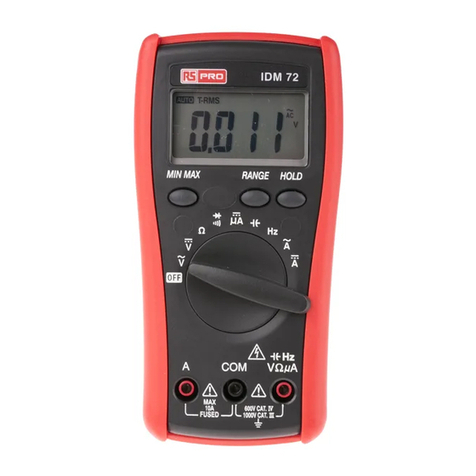
RS PRO RS-9889 User manual

Africa
RS Components SA
P.O. Box 12182,
Vorna Valley, 1686
20 Indianapolis Street,
Kyalami Business Park,
Kyalami, Midrand
South Africa
www.rs-components.com
Asia
RS Components Ltd.
Suite 1601, Level 16, Tower 1,
Kowloon Commerce Centre,
51 Kwai Cheong Road,
Kwai Chung, Hong Kong
www.rs-components.com
China
RS Components Ltd.
Suite 23 A-C
East Sea Business Centre
Phase 2
No. 618 Yan'an Eastern Road
Shanghai, 200001
China
www.rs-components.com
Europe
RS Components Ltd.
PO Box 99, Corby,
Northants.
NN17 9RS
United Kingdom
www.rs-components.com
Japan
RS Components Ltd.
West Tower (12th Floor),
Yokohama Business Park,
134 Godocho, Hodogaya,
Yokohama, Kanagawa 240-0005
Japan
www.rs-components.com
U.S.A
Allied Electronics
7151 Jack Newell Blvd. S.
Fort Worth,
Texas 76118
U.S.A.
www.alliedelec.com
South America
RS Componentes Limitada
Av. Pdte. Eduardo Frei M. 6001-71
Centro Empresas El Cortijo
Conchali, Santiago, Chile
www.rs-components.com
Instruction Manual
RS-9889
Stock No: 179-9512
True RMS Thermal MultiMeter
EN

1
True RMSThermal MultiMeter / English
19/07/2018 Version No. 001
1-Introduction
Professional True RMS Industrial Digital Multimeter with built-in Thermal Imager, and TFT color
LCD display, providing fast A/D converting sampling time, high accuracy. It is easy to find and solve
the problems of the production equipments, providing Bluetooth technology. It is much more safe
measurements with double molded plastic housing design and Ip65 waterproof function.
Key features
• 6000 count 2.8'' TFT Color LCD display
• Built-in Thermal imager with Max,Min and Center crosshair targeting
• 50Hz fast Thermal image frame rate
• DC voltage
• AC, AC+DC TRMS Voltage
• DC current
• AC, AC+DC TRMS current
• Resistance and Continuity test
• Diode test
• Capacity
• Frequency
• Duty Cycle
• Temperature with K-type probe
• flexible coils current
This symbol adjacent to another symbol, terminal or operating device indicates that the operator must refer
to an explanation in the Operating Instructions to avoid personal injury or damage to the meter.
WARNING This WARNING symbol indicates a potentially hazardous situation, which if not avoided, could result in
death or serious injury.
CAUTION This CAUTION symbol indicates a potentially hazardous situation, which if not avoided, may result damage
to the product.
This symbol advises the user that the terminal(s) so marked must not connected to a circuit point at which
the voltage with respect to earth ground exceeds (in this case) 1000 VAC or VDC.
This symbol adjacent to one or more terminals identifies them as being associated with ranges that may,
in normal use, be subjected to particularly hazardous voltages. For maximum safety, the meter and its test
leads should not be handled when these terminals are energized.
This symbol indicates that a device is protected throughout by double insulation or reinforced insulation.
2. Safety
2.1. safety infomation

2 3
Input Protection Limits
Function Maximum Input
V dc or V ac 1000Vdc/ac RMS
mA ac/dc 800mA 1000V fast acting fuse
A ac/dc 10A 1000V fast acting fuse
Frequency,Resistance, Capacitance
Duty Cycle,DiodeTest,Continuity 1000Vdc/ac rms
Temperature 1000Vdc/ac rms
Surge Protection: 8kV peak per IEC 61010
PER IEC1010 OVERVOLTAGE INSTALLATION CATEGORY
OVERVOLTAGE CATEGORY I
Equipment of OVERVOLTAGE CATEGORY I is equipment for connection to circuits in which measures
are taken to limit the transient overvoltages to an appropriate low level.
Note – Examples include protected electronic circuits.
OVERVOLTAGE CATEGORY II
Equipment of OVERVOLTAGE CATEGORY II is energy-consuming equipment to be supplied from the
fixed installation.
Note – Examples include household, office, and laboratory appliances.
OVERVOLTAGE CATEGORY III
Equipment of OVERVOLTAGE CATEGORY III is equipment in fixed installations.
Note – Examples include switches in the fixed installation and some equipment for industrial use with
permanent connection to the fixed installation.
OVERVOLTAGE CATEGORY IV
Equipment of OVERVOLTAGE CATEGORY IV is for use at the origin of the installation.
Note – Examples include electricity meters and primary over-current protection equipment
2.2.Safety Instructions
This meter has been designed for safe use, but must be operated with caution.
The rules listed below must be carefully followed for safe operation.
• NEVER apply voltage or current to the meter that exceeds the specied maximum:
• USE EXTREME CAUTION when working with high voltages.
• DO NOT measure voltage if the voltage on the “COM” input jack exceeds 1000V above earth ground.
• NEVER connect the meter leads across a voltage source while the function switch is in the current,
resistance, or diode mode. Doing so can damage the meter.
• ALWAYS discharge filter capacitors in power supplies and disconnect the power when making
resistance or diode tests.
• ALWAYS turn off the power and disconnect the test leads before opening the covers to replace the
fuse or batteries.
• NEVER operate the meter unless the back cover and the battery and fuse covers are in place and
fastened securely.
If the equipment is used in a manner not specified by the manufacturer, the protection provided by the
equipment may be impaired.
3.Discription and reference guide
3.1.Front and back descriptions
1-NCV detector area
2-LCD Display
3-Navigation/Menu buttons
4-MODE button
5-RANGE button
6-Rotary function switch
7-Positive(+) Probe input jack for A (Current).
8-Positive(+) Probe input jack for mA (Current).
9-COM(-) Probe input jack
10-Positive(+) Probe input jack for all Inputs except A and mA
11-Thermal mode/Light button
12-Hold/Capture button
Fig 3.1 Front view
Fig 3.2 Back view
1-No-slip slope
2-Thermal imager Len
3-Len cover
4-Work light
5-Laser
6-Support plate
7-Battery cover lock
True RMSThermal MultiMeter / EnglishTrue RMSThermal MultiMeter / English
19/07/2018 Version No. 00119/07/2018 Version No. 001

4 5
3.2.Understanding the Push Buttons
The 9 push buttons on the front of the Meter activate features that augment the function selected using
the rotary switch, navigate menus or control power to Meter circuits.
• Cursor buttons:
MAX PEAKREL
select an item in a menu, adjust display contrast, scroll through information, and perform data entry.
REL
Use Navigation UP buttons select PEAK function
MAX
Use Navigation Left buttons to select REL function
PEAK
Use Navigation Right buttons select MAX function
• Physical buttons:
Freezes the present reading in the display and allows the display to be saved. Also wake up for APO.
Press the MODE key to switch the functions;
Press the RANGE key to manual range.
Enter function of the menu selects.
Press the IR key to switch DMM MODE and IR+DMM MODE.
Navigation buttons.
Voltage is over 30V (AC or DC)
Warming
flexible coils
traditional clamps
Relative
High Edge time
AC Voltage or Current
DCVoltage or Current
AC+DC Voltage or Current
Continuity function
Diode function
Ohms
3.3.Understanding the Display
• Measurement on LCD Dispaly
1.Indication of battery charge level
2.Indication of measuring result
3.Indication of Automatic/Manual mode
4.Analogue bargraph
5.Indications associated with function keys
6.Indication of the system's time
7.Indication of measuring unit
8.SD card
9.Temperature measuring result
10.Indication of Automatic/Manual mode
11.Temperature unit
12.IR camera
13.Indication of measuring unit
14.Indication of measuring result
• Icons on LCD Display
3.4.Understanding the Rotary Switch
Select a primary measurement function by positioning the rotary switch
to one of the icons around its perimeter. For each function, the Meter
presents a standard display for that function (range, measurement units,
and modifiers). Button choices made in one function do not carry over into
another function.
VAC voltage measurements
VDC and AC+DC voltage measurements
Hz% Frequency and Duty measurements
CAP Resistance, Diode test, capacitance and CONTINUITY measurements
K Temp Temperature measurements
AAC, DC and AC+DC amps measurements
mA AC, DC and AC+DC milliamps measurements
μA AC, DC and AC+DC microampere measurements up to 6,000 μA
flexible coils current
True RMSThermal MultiMeter / EnglishTrue RMSThermal MultiMeter / English
19/07/2018 Version No. 00119/07/2018 Version No. 001
6 7
4.DMM Measurement and Setup
4.1.DC Voltage Measurements
Do not measure DC voltages if a motor on the circuit CAUTION: is
being switched
ON or OFF. Large voltage surges may occur that can damage the meter.
• Set the function switch to the VDC position.
• Insert the black test lead banana plug into the negative COM jack.
Insert the red test lead banana plug into the positive V jack.
• Read the voltage in the display.
4.2.AC+DC Voltage Measurements
CAUTION: Do not measure DC voltages if a motor on the circuit is
being switched ON or OFF. Large voltage surges may occur that can
damage the meter.
• Set the function switch to the VDC position.
• Insert the black test lead banana plug into the negative COM jack.
Insert the red test lead banana plug into the positive V jack.
• Press the MODE key to switch the V AC+DC Voltage functions.
• Read the AC+DC voltage in the display.
4.3.AC Voltage Measurements
WARNING: Risk of Electrocution. The probe tips may not be long
enough to contact the live parts inside some 240V outlets for
appliances because the contacts are recessed deep in the outlets. As
a result, the reading may show 0 volts when the outlet actually has
voltage on it. Make sure the probe tips are touching the metal contacts
inside the outlet before assuming that no voltage is present.
CAUTION: Do not measure AC voltages if a motor on the circuit is
being switched ON or OFF. Large voltage surges may occur that can
damage the meter.
• Set the function switch to the VAC position.
• Insert the black test lead banana plug into the negative COM jack.
Inser t red test lead banana plug into the positive V jack.
• Read the voltage in the main display.
4.4.Frequency Measurements
• Set the function switch to the Hz% position.
• Insert the black test lead banana plug into the negative COM jack.
Insert the red test lead banana plug into the positive V jack.
• Read the Frequency in the display.
• Press the MODE key to switch the Duty functions.
• Read the Duty in the display.
True RMSThermal MultiMeter / EnglishTrue RMSThermal MultiMeter / English
19/07/2018 Version No. 00119/07/2018 Version No. 001
8 9
4.5.Resistance Measurements
To avoid electric shock, disconnect power to the unit under test and
discharge all capacitors before taking any resistance measurements.
Remove the batteries and unplug the line cords.
• Set the function switch to the CAP position.
• Insert the black test lead banana plug into the negative COM jack.
Insert the red test lead banana plug into the positive Ω Jack.
• Read the resistance in the display.
4.6.Continuity Check
WARNING: To avoid electric shock, disconnect power to the unit
under test and discharge all capacitors before taking any resistance
measurements. Remove the batteries and unplug the line cords.
• Set the function switch to the CAP position.
• Insert the black test lead banana plug into the negative COM jack.
Insert the red test lead banana plug into the positive jack.
• Press the MODE key to switch the continuity functions.
• If the resistance is less than approximately 50Ω, the audible signal
will sound.
If the circuit is open, the display will indicate “OL”.
4.7.Diode Test
• Set the function switch to the CAP position.
• Insert the black test lead banana plug into the negative COM jack
and the red test lead banana plug into the positive V jack.
• Press the MODE key to switch the Diode functions.
• For ward voltage will typically indicate 0.400 to 3.000V. Reverse
voltage will indicate “OL”. Shorted devices will indicate near 0V and
an open device will indicate “OL” in both polarities.
4.8.Capacitance Measurements
WARNING: To avoid electric shock, disconnect power to the unit
under test and discharge all capacitors before taking any capacitance
measurements. Remove the batteries and unplug the line cords.
• Set the rotary function switch to the CAP position.
• Insert the black test lead banana plug into the negative COM jack.
Insert the red test lead banana plug into the positive V jack.
• Press the MODE key to switch the Capacitance functions.
• Read the capacitance value in the Display
True RMSThermal MultiMeter / EnglishTrue RMSThermal MultiMeter / English
19/07/2018 Version No. 00119/07/2018 Version No. 001

10 11
4.9.Temperature Measurements
• Set the function switch to the TEMP(°C or °F) position.
• Insert the Temperature Probe into the input jacks, making sure to
observe the correct polarity.
• Read the temperature in the display.
• Press the MODE key to switch the Unit (°C or °F).
4.10.Fexible Coil Current Measurements
• Set the function switch to the Flexible coil position.
• Insert the black test lead banana plug into the negative COM jack. Insert the red test lead banana plug
into the positive V jack.
• Read the currnet in the display.
• Press the MODE key to switch the AC ,DC and AC+DC Current.
• Press the RANGE key to switch range.1000mA,10A,30A,40A,100A,300A,400A,1000A,3000A.
4.11.DC Current Measurements
• Insert the black test lead banana plug into the negative COM jack.
• For current measurements up to 6000μA DC, set the function switch
to the μA position and insert the red test lead banana plug into the
μA/mA jack.
• For current measurements up to 600mA DC, set the function switch
to the mA position and insert the red test lead banana plug into the
μA/mA jack.
• For currentmeasurements up to 10A DC, set the function switch to
the 10A position and insert the red test lead banana plug into the
10A jack.
• Press the MODE button to indicate “ ” on the display.
• Read the current in the display.
4.12.AC Current Measurements
CAUTION: Do not make 10A current measurements for longer than 30
seconds. Exceeding 30 seconds may cause damage to the meter and/or
the test leads.
• Insert the black test lead banana plug into the negative COM jack.
• For current measurements up to 6000μA AC, set the function switch
to the yellow μA position and insert the red test lead banana plug
into the μA/mA jack.
• For current measurements up to 600mA AC, set the function switch
to the yellow mA position and insert the red test lead banana plug
into the μA/mA jack.
• For current measurements up to 10A AC, set the function switch to
the yellow 10A position and insert the red test lead banana plug into
the 10A jack.
• Press the MODE button to indicate “ ” on the display.
• Read the current in the display
True RMSThermal MultiMeter / EnglishTrue RMSThermal MultiMeter / English
19/07/2018 Version No. 00119/07/2018 Version No. 001
12 13
4.13.AC+DC Current Measurements
CAUTION: Do not make 10A current measurements for longer than 30
seconds.
Exceeding 30 seconds may cause damage to the meter and/or the test
leads.
• Insert the black test lead banana plug into the negative COM jack.
• For current measurements up to 6000μA AC+DC, set the function
switch to the yellow μA position and insert the red test lead banana
plug into the μA/mA jack.
• For current measurements up to 600mA AC+DC, set the function
switch to the yellow mA position and insert the red test lead banana
plug into the μA/mA jack.
• For current measurements up to 10A AC+DC, set the function
switch to the yellow 10A position and insert the red test lead banana
plug into the 10A jack.
• Press the MODE button to indicate “ ” on the display.
• Read the current in the display.
4.14.Using RANGE
Press the RANGE key to activate the manual mode and to disable the
Autorange function. The message “Manual Range” appears on the
upper left part of the display instead of “Auto Range”. In manual mode,
press the RANGE key to change measuring range: the relevant decimal
point will change its position. The RANGE key is not active in positions
TempoCoF10A In Autorange mode, the instrument selects
the most appropriate ratio for carrying out measurement. If a reading
is higher than the maximum measurable value, the indication “O.L”
appears on the display. Press and hold the RANGE key for more than 1
second to exit the manual mode and restore the Autorange mode.
4.15.Hold Mode
To freeze the display for any function,press key HOLD.
And again press key HOLD to release freeze.
4.16.Capturing Minimum and Maximum Values
The MAX MIN Record mode captures minimum, and maximum input
values.
When the input goes below the recorded minimum value or above the
recorded maximum value, the Meter beeps and records the new value.
This mode is for capturing intermittent readings, recording minimum
and maximum readings unattended, or recording readings while
equipment operation precludes watching the Meter.
To activate the MAX MIN mode, press soft key labeled . If the Meter
is already in MAX MIN function, press causes the Meter to turn off
MAX MIN function.
4.17.Relative Values
To activate the relativemode, press the soft key labeled .
If the Meter is already in the relative function, press causes the
Meter to turn off relative.
True RMSThermal MultiMeter / EnglishTrue RMSThermal MultiMeter / English
19/07/2018 Version No. 00119/07/2018 Version No. 001
14 15
4.18.Capturing Peak Values
To activate the peak mode, press the soft key labeled .
If the Meter is already in the peak function, press causes the Meter
to turn off peak.
4.19.Non-Contact AC Voltage Detector (100 to 1000V AC)
WARNING: Risk of Electrocution. Before use, always test the Voltage
Detector on a known live circuit to verify proper operation.
WARNING: Insulation type and thickness, distance from the source, and
other factors may effect operation. Always verify live voltage using
other methods before working on electrical circuits.
• The non-contact voltage detector operates when the meter is set
to any measuring function. The detector does not operate when Auto
Power Off turns the meter off or when the rotary function switch is
set to the off position.
• Slowly move the detector probe closer to the conductor being tested.
• If AC voltage within the specified range is present, the indicator light
will illuminate.
NOTES: The detector is designed with high sensivity. Static electricity and other sources of electrical
energy may randomly activate the detector. This is normal operation. The detector only activates the
indicator light when AC voltage is present.
It does not indicate the voltage level on the LCD display.
5.Thermal imager and DMM opertion
5.1.Thermal imager basics
In the Thermal imaging and DMM mode. User can mearsure a targeted surface’s temperature and user
can use Mutimeter at the same time, the measured result will display under the themal image.
• Press the red “IR” button to open the Thermal Imager. In Fig5-1 the thermal image is set to color
palette IRON. Select other palettes in the Menu Settings.
• Open the protective lens cover on the back of the meter.
1.The Battery capacity indicator.
2.SD card icon, if this icon is displayed, there is a SD card inserted.
3.Bluetooth icon, if this icon is displayed, the BlueTooth is opened.
4.The currently selected Emissivity value. Use the Thermal Settings Menu to change the emissivity value.
5.The temperature unit icon, Use the Thermal Settings Menu to select “oC”, oF, K.
6.Current time Display
7.Center cross of the Thermal imager Temper ture Measurement, represents the center spot temperature
of the scene.
8.Highest temperature spot of the Thermal imager Temper ture Measurement, represents the highest
spot temperature of the scene.
9.Minimum temperature spot of the Thermal imager Temperture Measurement, represents the
Minimumspot temperature of the scene.
10.Current scene ot theThermal image frame
11.Range icon of the meter
12.Max soft button
13.REL soft button
14.PEAK soft button
15.DMM measurement is shown below the thermal image.
16.Unit of the meter
17.Lowest reading measured in the current frame
18.The Thermal scale shows the range color for thermal images, The lighter the color, the warmer the
temperature; The darker the color, the cooler the temperature.
19.Highest reading measured in the current frame.
True RMSThermal MultiMeter / EnglishTrue RMSThermal MultiMeter / English
19/07/2018 Version No. 00119/07/2018 Version No. 001
16 17
5.2.Using the thermal imager
For basic operation follow these steps:
1.Set the function switch to any position.
2.Press the “IR” button to switch the thermal imager ON. Target the object by the thermal imager len.
3.The display will show the temperature measurement in the upper left hand corner for the targeted area
along with the currently selected emissivity value.
4.In the Thermal imaging mode, the laser pointer and dispay cross hairs can be used to assist in
targeting. These tools can be switched ON or OFF in the Setting menu.
5.In the Thermal imaging mode, the highest temperature will auto marked by a red cross, and the lowest
temperature will auto marked by a blue cross, the two spots can be switched ON or OFF in the Setting
menu.
6.In the Thermal imaging mode, the meter continues to operate normally as a Multimeter allowing any of
the electrical functions to be used.
7.Press the HOLD button to hold the thermal image frame, then long press the HOLD button, you will
capture the screen and save a bitmap with measure data into SD card, the saved bitmap later can be
analysed by the PC software or smartphone APPs.
8.The thermal imager’s FOV (Field of view) is 21 by 21 degrees.
9.FOV is the largest area that your imager can see at a set distance.
10.This table lists the horizontalFOV, vertical FOV and IFOV for lens.
Focal Length Horizontal FOV Vertical FOV IFOV
7.5mm 21° 21° 4.53mrad
IFOV (Instantaneous Field of View) is the smallest detail within the FOV that can be detected or seen at
a set distance, the unit is rad. The formula is this:
IFOV = ( Pixel Size )/ ( Lens focal length );
D:Stheoretical ( = 1/ IFOVtheoretical ) is the calculated spot size based on the pixel size of the Thermal Imager
detector array and theoretical theoretical lens focal length.
Example: If Thermal Imager uses 9mm lens, because the Pixel Size of detector is 34um.
Horizontal FOV is 21°, Vertical FOV is 21°, the IFOV is 34um/7.5mm = 4.53mrad;
D:Stheoretical ( = 1/ IFOVtheoretical ) = 220:1
80m
21°
21°
220m
80m
Spot Size=100.00cm*100.00cm
(Based upon IFOVtheoretical)
D:Stheoretical ( = 1/ IFOVtheoretical ) is the spot size needed to provide an accurate temperature measure.
Typically, D:Stheoretical is 2 to 3 times smaller than D:Stheoretical , which means the temperature measurement
area of the target need to be 2 to 3 times theoretical larger than that determined by the calculated
theoretical D:S.
5.3.Using the Multimeter with the thermal imager
on IR+DMM mode, MODE key, RANGE key, HOLD key and REL
Function is same DMM mode.
• Capturing MAXMIN Values on IR+DMM mode
1.To activate the maxmin mode, press the softkey labeled , and
display max value.
2.If the Meter is already in the maxmin function, then Press the
key to display min value, then Press the key to display current
measurement value. next press again display max value.
3.The Press and hold the key for more than 1 second tocauses the
Meter to turn off maxmin.
• Capturing Peak Values on IR+DMM mode
1.To activate the peak mode, press the softkey labeled , and display
Peak max value.
2.If the Meter is already in the peak function, then Press the key
to display Peak min value, then Press the key to display current
measurement value. next press again display Peak max value.
3.The Press and hold the key for more than 1 second to causes the
Meter to turn off peak.
True RMSThermal MultiMeter / EnglishTrue RMSThermal MultiMeter / English
19/07/2018 Version No. 00119/07/2018 Version No. 001
18 19
6.Settings Menus
6.1.Using Settings Menus
• Press MENU button to open the Settings Menus, as show below.
• Press UP/DOWN button to select menu item or change the value of current focus item.
• Press RIGHT/MENU button to enter the submenu or set focus on the current sellected item.
Press LEFT button to return to the previous menu.
• If want to exit settings menus, can press MODE/RANGE/HOLD/IR button or press LEFT button in root menu.
6.2.Settings details
• Palette mode
Thermal imager has five kinds of palette, such as:
Press RIGHT/MENU button to select one of the display color palettes.
6.3.Temp Unit
Press RIGHT/MENU button to set focus on this option and the color of option value will change to black
. Infocus state, use the RIGHT/MENU button to toggle oC, oF and K, use LEFT/RIGHT/MENU button
to exit focus state and the color of option value will change white .
6.4.Measure
Press RIGHT/MENU button to enter measure menu.
Two selections are available: HOT POINT and COLD POINT. Press
RIGHT/MENU button to set cur select item on or off.
• Hot point: This option enables thermal imager automatically detect
the highest temperature point.
• Cold point: This option enables thermal imager automatically detect
the lowest temperature point.
6.5.Emissivity
• Press RIGHT/MENU button to set focus on this option. In focus state, use UP /DOWN button to
increase or decrease emissivity's value, use LEFT/RIGHT/MENU button to exit focus state. The available
range is 0.01 to 0.99 in 0.01 steps.
6.6.Language
• Press RIGHT/MENU button to to enter language menu.
Three options are available: Simplified Chinese, Traditional Chinese and
English.
Use UP/DOWN button to select language and use RIGHT/MENU button
to set selected language to be valid.
6.7.Setup
Press RIGHT/MENU button to enter Setup menu.
Five options are available: Beep, Bluetooth, Laser, Brightness and Auto Off.
• Beep:Use RIGHT/MENU button to set beep on or off.
• Bluetooth: Use RIGHT/MENU button to set bluetooth power on or off.
• Laser: Use RIGHT/MENU button to set laser pointer on or off.
• Brightness: Press RIGHT/MENU button to set focus on this option.
In focus state, use UP/DOWN button to change LCD's brightness,
use LEFT/RIGHT/MENU button to exit focus state. The available
brightness's range is 100% to 10% in 10% steps.
• Auto Off: Press RIGHT/MENU button to set focus on this option.
In focus state, use UP/DOWN button to choose the time period after
which the meter enters the sleep mode.
6.8.Bluetooth Connect
1.Turn on the Bluetooth function on the instrument.
True RMSThermal MultiMeter / EnglishTrue RMSThermal MultiMeter / English
19/07/2018 Version No. 00119/07/2018 Version No. 001
20 21
2.Turn on the bluetooth of smartphone, press
the icon Thermview+and enter into the home
interface, Then press Connect Device icon on
the Home interface, bluetooth device name
will appear.
3.Touch the device name listed in Bluetooth
deviceslistto connect the device.
The detail information about Thermview+,
please refer to Thermview+ APP help file.
Thermview+ for Android:
Please search in Google Play with keyword
“Thermview+”,download and run.
Thermview+ for iOS:
Please search in Apple store with keyword
“Thermview+”,download and run.
6.9.Time/Date
Press RIGHT/MENU button to enter time menu. In this menu, yeas,
month, day, hour, minute and time formate can be set. The changes
take effect after exitting settings menus.
6.10.Photo
Press RIGHT/MENU button to enter photo menu.
Two options are available: Photo Review and Delete Photo.
• Photo Review: Press RIGHT/MENU button to enter image browser
function, and eixt settings menus immediately.
• Delete Photo: After Press RIGHT/MENU button, dialog box will be
displayed as show below. Warnning: Select 'YES', will delete all the
photos in the memory card which captured by user.
6.11.Sys Info
Press RIGHT/MENU button to enter system infomation menu.This menu
contains software's version, hardware's version and thermal imager's
version.
6.12.Factory Set
When select Factory Set option, after press RIGHT/MENU button,
thedialog box will be displayed as show below. Select 'YES' button,
system parameter will be reset.
True RMSThermal MultiMeter / EnglishTrue RMSThermal MultiMeter / English
19/07/2018 Version No. 00119/07/2018 Version No. 001
22 23
6.13 Record measurements
• With a measurement on the display(Fig130), press Button key Menu to enter the instrument’s general
menu(Fig131).
The screen is shown on the display. Press the Button or key to select Reord Item. Press the
Button Enter Record Menu(Fig132).
Fig130
Fig133
Fig131
Fig134
Fig132
Fig135
Fig136
Fig137
• In Record Menu. Press the Button or key to select Sample Interval Item or Duration Item.
Press the Button Enter Record setting. Then Press the Button or key to adjust time.
(Fig133)Setting of sampling interval from 1s to 59min:59s.
(Fig134)Setting of recording duration, from 1min to 9h:59min.
• In Record Menu. Press the Button or key to select Start record
Item.
Press the Button Enter Save Record measurement (Fig135).
In Save Record measurement, Press the Button to stop record. and
Press the Button Save.
• In Record Menu. Press the Button or key to select Review Item.
Press the Button Enter View Record measurement (Fig136).
Press the Button MODE key to Trend record(Fig137). And Press the
Button or key to select previous record measurement or next
record measurement.
And press the Button ESC key to exit view record measurement.
True RMSThermal MultiMeter / EnglishTrue RMSThermal MultiMeter / English
19/07/2018 Version No. 00119/07/2018 Version No. 001

24 25
Fig138
Fig139
In Record View Display, And Press the Button or key to move the
cursor on the graph.
And the Button key to activate the Zoom function of the graph
(Fig138), increasing resolution (symbol “Zoom Xy” where y=max zoom
dimension appears at the top of the display on the right side).You can
zoom X1 for at least 10 measuring points, X2 for at least 20 measuring
points, X3 for at least 40 measuring points and so on for maximum 6
zooming operations.
• In Record Menu. Press the Button or key to select Delete all
Recordings
Item(Fig139). Press the Button Enter Delete Box. And select Yes
or No.
7.Image Browser
• In Image Browser mode. User can browse the pictures in the memory
card.
Press LEFT RIGHT button / to select prev or next picture. Press any
other keys to exit Image Browser mode.
1.LEFT key instruction.
2.Current displayed picture's filename.
3.RIGHT key instruction.
4.Picture display area.
• How to capture screen
When in DMM mod or Thermal imaging + DMM mode, use HOLD button to enter hold mode, as show
below. Then press UP button to capture screen. After saving to TF card completly, multimeter will exit
hold mode.
True RMSThermal MultiMeter / EnglishTrue RMSThermal MultiMeter / English
19/07/2018 Version No. 00119/07/2018 Version No. 001
26 27
8.Technical specications
8.1.Technical characteristics
• Thermal imager
Field of view (FOV) / Minimum focus distance 21° x 21°/ 0.5m
Spatial resolution (IFOV) 4.53mrad
IR resolution 80 × 80 pixels
Thermal sensitivity/NETD < 0.1°C @ +30°C (+86°F) / 100 mK
Image frequency 50Hz
Focus mode Focus free
Focal length 7.5mm
Focal Plane Array (FPA)/Spectral range Uncooled microbolometer / 8–14 μm
Object temperature range –20°C to +260°C (–4°F to +500°F)
Accuracy ±3°C (±5.4°F) or ±3% of reading (Environment
temperature 10°C-35°C, object temperature >0°C. )
Range Resolution Accuracy
Input impedance Protection against overcharge
600.0mV 0.1mV
±(0.09%reading + 5digits)
>10MΩ 1000Vdc/ac rms
6.000V 0.001V
60.00V 0.01V
600.0V 0.1V
±(0.2%reading + 5digits)
1000V 1V
Range Resolution
Accuracy (50Hz~1kHz) Input impedance Protection against overcharge
6.000V 0.001V
±(2.4%reading +20dgt)
>10MΩ 1000Vdc/ac rms
60.00V 0.01V
600.0V 0.1V
1000V 1V
Range Resolution Accuracy
Protection against overcharge
600.0uA 0.1uA
±(0.9%reading + 5digits) Quick fuse 800mA/1000V
6000uA 1uA
60.00mA 0.01mA
600.0mA 0.1mA ±(0.9%reading + 8digits)
10.00A 0.01A ±(1.5%reading + 8digits) Quick fuse 10A/1000V
Range Resolution Accuracy (*) (50Hz~1kHz)
Protection against overcharge
600.0uA 0.1uA
±(1.2%reading + 5digits) Quick fuse 800mA/1000V
6000uA 1uA
60.00mA 0.01mA
600.0mA 0.1mA
10.00A 0.01A ±(1.5%reading + 5digits) Quick fuse 10A/1000V
Range Resolution (50Hz~60Hz) (61Hz~1kHz)
Protection against overcharge
30.00A 0.01A ±(0.8%reading+
5digits)
±(2.4%reading+
5dgt) 1000Vdc/ac rms300.0A 0.1A
3000A 1A
Function Test current Max voltage with open circuit
<1.5mA 3.3Vdc
Range Resolution Accuracy(*) Protection against overcharge
(50Hz÷60Hz) (61Hz÷1kHz)
1000Vdc/ac rms
6.000V 0.001V
±(0.8%reading+
5digits)
±(2.4%reading+
5dgt)
60.00V 0.01V
600.0V 0.1V
1000V 1V
Accuracy calculated as [%reading + (num. digits*resolution)] at 18°C ÷ 28°C <75%HR
• DC Voltage
• AC+ DC TRMS Voltage
• DC Current
• AC TRMS Current
• Flexible coil Current
• Diode test
• AC TRMS Voltage
(*) Accuracy specified from 10% to 100% of the measuring range, sine wave.
Input impedance: >9MΩ;
Accuracy PEAK function: ±10%rdg, PEAK response time: 1ms
(*) Accuracy specified from 5% to 100% of the measuring range, sine wave.
Accuracy PEAK function: ±10%rdg , AC+DC TRMS Current: accuracy (50Hz÷1kHz): ±(3.0%reading + 20dgt)
True RMSThermal MultiMeter / EnglishTrue RMSThermal MultiMeter / English
19/07/2018 Version No. 00119/07/2018 Version No. 001

28 29
Range Resolution Accuracy Buzzer
Protection against overcharge
600.0Ω 0.1Ω ±(0.5%reading + 10dgt)
>50Ω 1000Vdc/ac rms
6.000kΩ 0.001kΩ
±(0.5%reading + 5digits)
60.00kΩ 0.01kΩ
600.0kΩ 0.1kΩ
6.000MΩ 0.001MΩ
60.00MΩ 0.01MΩ ±(2.5%reading + 10dgt)
Range Resolution Accuracy
Protection against overcharge
60.00Hz 0.01Hz
±(0.09%rdg+5digits) 1000Vdc/ac rms
600.0Hz 0.1Hz
6.000kHz 0.001kHz
60.00kHz 0.01kHz
600.0kHz 0.1kHz
6.000MHz 0.001MHz
10.00MHz 0.01MHz
Range Resolution Accuracy
Protection against overcharge
60.00nF 0.01nF ±(1.5%reading+20digits)
1000Vdc/ac rms
600.0nF 0.1nF ±(1.2%reading+8digits)
6.000uF 0.001uF ±(1.5%reading+8digits)
60.00uF 0.01uF ±(1.2%reading+8digits)
600.0uF 0.1uF ±(1.5%reading+8digits)
6000uF 1uF ±(2.5%reading+20digits)
• Resistance and Continuity test
• Frequency (electronic circuits)
• Capacity
Range Resolution Accuracy
Protection against overcharge
40.00Hz~10kHz 0.01Hz~0.001kHz ±(0.5%reading) 1000Vdc/ac rms
Range Resolution Accuracy
5.0%~95.0% 0.1% ±(1.2%reading + 2digits)
Range Resolution Accuracy (*) Protection against overcharge
-40.0°C ~ 600.0°C 0.1°C ±(1.5%reading + 3°C)
1000Vdc/ac rms
600°C ~ 1000°C 1°C
-40.0°F ~ 600.0°F 0.1°F ±(1.5%rdg+ 5.4°F)
600°F ~ 1800°F 1°F
• Frequency (electronic circuits)
• Duty Cycle
• Temperature with K-type probe
Sensitivity: >2Vrms (@20% 80% duty cycle) and f<100kHz;
>5Vrms (@20% 80% duty cycle) and f>100kHz
Pulse frequency range: 40Hz÷10kHz, Pulse amplitude:±5V (100us÷100ms)
(*) Instrument accuracy without probe; Specified accuracy with stable environmental
temperature at ±1°C.
For long-lasting measurements, reading increases by 2°C.
• Reference standards
Safety IEC/EN61010-1; UL STD. 61010-1
EMC IEC/EN 61326-1
Insulation double insulation
Pollution level 2
Overvoltage category CAT IV 600V, CAT III 1000V
Max operating altitude 2000m (6562ft)
• Power supply
Battery type 1x7.4V rechargeable Li-ION battery, 1500mAh
Battery charger power supply 100/240Vac, 50/60Hz, 12Vdc, 2A
Low battery indication symbol “ ” on the display
Auto Power Off after 15 - 60min minutes’ idling (may be disabled)
Fuses F10A/1000V, 10 x 38mm (input 10A)
F800mA/1000V, 6 x 32mm (input mA uA)
• Display
Conversion TRMS
Characteristics colour TFT, 6000 dots with bargraph
Sampling frequency 3 times/s
8.2.Environment
Environmental conditions for use
Reference temperature 18°C - 28°C (64°F - 82°F)
Operating temperature 5°C - 40°C (41°F - 104°F)
Allowable relative humidity <80%HR
Storage temperature -20° - 60°C (-4°F - 140°F)
Storage humidity <80%HR
True RMSThermal MultiMeter / EnglishTrue RMSThermal MultiMeter / English
19/07/2018 Version No. 00119/07/2018 Version No. 001
31
Manuel d'instructions
RS-9889
No d'inventaire: 179-9512
Multimètre thermique à valeur efcace
FR
1-Introduction
Multimètre numérique industriel True RMS professionnel avec imageur thermique intégré, écran LCD
couleur TFT, permettant une conversion rapide A / N du temps d’échantillonnage et une grande précision.
Il est facile de trouver et de résoudre les problèmes des équipements de production grâce à la technologie
Bluetooth.Il s'agit de mesures beaucoup plus sûres avec la conception de boîtier en plastique double
moulage et la fonction imperméable Ip65.
Principales caractéristiques
• Ecran LCD couleur TFT 6000 ", 2,8"
• Imageur thermique intégré avec ciblage en croix sur les cibles maximale, minimale et centrale
• Frame rate d'images thermiques rapides 50 Hz
• Tension continue
• Tension TRMS CA, CA + CC
• courant continu
• Courant TRMS AC, AC + DC
• Test de résistance et de continuité
• Test de diode
• Capacité
• La fréquence
• Cycle de service
• Température avec sonde de type K
• courant flexible de bobines
2. Sécurité
2.1. informations de sécurité
Ce symbole adjacent à un autre symbole, terminal ou dispositif de commande indique que l'opérateur doit
se reporter à une explication dans les instructions d'utilisation pour éviter des blessures corporelles ou des
dommages au compteur.
WARNING Ce symbole AVERTISSEMENT indique une situation potentiellement dangereuse , si elle n'est pas évitée, pourrait
entraîner la mort ou des blessures graves.
CAUTION Ce symbole ATTENTION indique une situation potentiellement dangereuse , si elle n'est pas évitée, peut
endommager le produit
Ce symbole indique à l'utilisateur que làoù les bornes ainsi marquées ne doivent pas être connectées à un point de
circuit auquel la tension par rapport à la terre dépasse (dans ce cas) 1000 V ca ou V cc.
Ce symbole adjacent à un ou plusieurs terminaux les identifie comme étant associés à des gammes qui, en
utilisation normale, peuvent être soumises à des tensions particulièrement dangereuses.Pour une sécurité
maximale, le compteur et ses cordons de test ne doivent pas être manipulés lorsque ces bornes sont sous tension.
Ce symbole indique qu'un dispositif est entièrement protégé par une double isolation ou une isolation renforcée.
Multimètre thermique à valeur efcace / Francais
18/12/2018 Version No. 001
1 2
Multimètre thermique à valeur efcace / Francais Multimètre thermique à valeur efcace / Francais
18/12/2018 Version No. 00118/12/2018 Version No. 001
PER IEC1010 CATÉGORIE D'INSTALLATION DE SURTENSION
CATÉGORIE I
L'équipement de la CATÉGORIE DE SURTENSION I est un équipement de connexion à des circuits dans
lesquels des mesures sont prises pour limiter les surtensions transitoires à un niveau bas approprié.
Remarque- Les exemples incluent les circuits électroniques protégés.
CATÉGORIE DE SURTENSION II
L'équipement de SURVOLTAGE CATÉGORIE II est un équipement consommateur d'énergie qui doit être
fourni par l'installation fixe.
Remarque- Les exemples comprennent les appareils ménagers, de bureau et de laboratoire.
CATÉGORIE DE SURTENSION III
L'équipement de la CATÉGORIE DE SURTENSION III est l'équipement dans les installations fixes.
Remarque- Les exemples incluent les commutateurs dans l'installation fixe et certains équipements à
usage industriel avec connexion permanente à l'installation fixe.
CATÉGORIE DE SURTENSION IV
L'équipement de SURVOLTAGE CATÉGORIE IV est à utiliser à l'origine de l'installation.Remarque-
Les exemples comprennent les compteurs d'électricité et l'équipement de protection primaire contre les
surintensités.
Limites de protection d'entrée
Function Entrée Maximum
V dc or V ac 1000Vdc/ac RMS
mA ac/dc Fusible à action rapide 800 mA 1000 V
A ac/dc Fusible rapide 10 A 1000 V
Fréquence, Résistance, Capacitance,
Cycle de service, test de diode, continuité 1000Vdc/ac rms
Température 1000Vdc/ac rms
Protection contre les surtensions: pic de 8 kV selon IEC 61010
• FAITES EXTREME ATTENTION lorsque vous travaillez avec des tensions élevées.
• NE PAS mesurer la tension si la tension sur la prise d'entrée "COM" dépasse 1000 V au-dessus de la
terre.
• NE JAMAIS raccorder les fils du multimètre à une source de tension tant que le commutateur d est en
mode courant, résistance ou diode. Cela pourrait endommager le compteur.
• TOUJOURS décharger les condensateurs de filtrage dans les alimentations et déconnecter l'alimentation
lors des tests de résistance ou de diode.
2.2. Consignes de sécurité
Ce compteur a été conçu pour une utilisation sûre, mais doit être utilisé avec prudence. Les règles énumérées
ci-dessous doivent être soigneusement suivies pour un fonctionnement sûr.
• NE JAMAIS appliquer de tension ou de courant au compteur qui dépasse le maximum spécifié:
• TOUJOURS couper l'alimentation et débrancher les cordons avant d'ouvrir les capots pour le remplacer
ou les fusibles.
• NE JAMAIS utiliser l'appareil à moins que le couvercle arrière de la batterie et le couvercle des fusibles
ne soient en place et solidement fixés.
Si l'équipement est utilisé d'une manière non spécifiée par le fabricant, la protection fournie par
l'équipement peut être compromise.
3.Description et guide de référence
3.1.Descriptions avant et arrière
1-Zone de détection NCV
2-L’écran LCD
3-Boutons de navigation / menu
4-Bouton MODE
5-Bouton RANGE
6-Commutateur de fonction rotatif
7-Prise d'entrée de sonde positive (+) pour A (courant).
8-Prise d'entrée de sonde positive (+) pour mA (courant).
9-COM (-) Prise d'entrée de la sonde
10-Prise d'entrée de sonde positive (+) pour toutes les
entrées sauf A et mA
11-Bouton mode thermique / lumière
12-Bouton Hold / Capture
Fig 3.1 Vue de face
Fig 3.2 Vue de face
1-Pente sans glissement
2-Imageur thermique Len
3-Couverture Len
4-Lampe de travail
5-Laser
6-Plaque de support
7-Verrou du couvercle de la batterie

3 4
3.2.Comprendre les boutons-poussoirs
Les 9 boutons situés à l'avant du multimètre activent des fonctions qui complètent la fonction
sélectionnée à l'aide du commutateur rotatif, permettent de naviguer dans les menus ou de contrôler
l'alimentation des circuits du multimètre.
• Boutons de curseur:
MAX PEAKREL
sélectionnez un élément dans un menu, réglez le contraste de l'affichage, faites défiler les informations
et effectuez la saisie de données.
REL
Utilisez les boutons de navigation UP pour sélectionner la fonction PEAK
MAX
Utilisez les boutons de navigation gauche pour sélectionner la fonction REL
PEAK
Utilisez les boutons de navigation à droite pour sélectionner la fonction MAX
• boutons physiques:
Gèle la lecture en cours sur l’affichage et permet de sauvegarder celui-ci.Réveillez-vous également pour APO.
Appuyez sur la touche MODE pour changer de fonction
Appuyez sur la touche RANGE pour passer en mode manuel.
Entrez la fonction du menu sélectionne.
Appuyez sur la touche IR pour basculer entre DMM MODE et IR + DMM MODE.
Boutons de navigation.
3.3.Comprendre l'afchage
• Mesure sur écran LCD
1. Indication du niveau de charge de la batterie
2. Indication du résultat
3. Indication du mode automatique / manuel
4. bargraphe analogique
5. Indications associées aux touches de fonction
6. Indication de l'heure du système
7. Indication de l'unité
La tension est supérieure à 30V (AC ou DC)
Chauffage
bobines flexibles
pinces traditionnelles
Relatif
Temps de pointe élevé
Tension ou courant alternatif
Tension ou courant continu
Tension ou courant alternatif + continu
Fonction de continuité
Fonction diode
Ohms
8. Carte mémoire SD
9. résultat de mesure de température
10. Indication du mode automatique / manuel
11. Unité de température
12. Caméra IR
13. Indication de l'unité de mesure
14. Indication du résultat de la mesure
• Icônes sur l'écran LCD
3.4.Comprendre le commutateur rotatif
Sélectionnez une fonction principale en positionnant sur le commutateur
rotatif à l'une des icônes autour de son périmètre. Pour chaque fonction,
le mètre présente un affichage standard pour cette fonction (gamme,
unités de mesure, et modificateurs).Les choix de boutons effectués dans
une fonction ne sont pas reportés dans Une autre fonction.
VMesures de tension alternative
VMesures de tension continue et alternative + continue
Hz% Mesures de fréquence et de service
CAP Résistance, test de diode, mesures de capacité et de CONTINUITÉ
K Temp Mesures de température
AMesures ampères AC, DC et AC + DC
mA Mesures milliampères AC, DC et AC + DC
μA Mesures microampères AC, DC et AC + DC jusqu'à 6000> ^A
courant flexible de bobines
Multimètre thermique à valeur efcace / Francais Multimètre thermique à valeur efcace / Francais
18/12/2018 Version No. 00118/12/2018 Version No. 001

5 6
4.4.Mesures de fréquence
• Réglez le commutateur en position Hz% verte.
• Insérez la fiche banane du fil noir dans la prise COM négative. Insérez
la fiche banane du fil rouge dans la prise V positif.
• Lisez la fréquence sur l'écran.
• Appuyez sur la touche MODE pour activer les fonctions de service.
• Lisez le devoir sur l'écran.
4.Mesure et conguration du multimètre
numérique
4.1.Mesures de tension continue
Ne mesurez pas les tensions CC si un moteur est sur le circuit.
ATTENTION: est en cours de commutation.
Allumé ou éteint.De fortes surtensions peuvent se produire et
endommager le compteur.
• Réglez le sélecteur de fonction sur la position VDC.
• Insérez la fiche banane du fil d’essai noir dans la prise COM négative.
Insérez la fiche du fil d’essai rouge dans la prise V positive.
• Lisez la tension affichée.
4.2.Mesures de tension AC + DC
MISE EN GARDE: Ne mesurez pas les tensions du courant continu si
un moteur du circuit est en marche ou à l'arrêt. De fortes surtensions
peuvent se produire et endommager le compteur.
• Réglez le sélecteur de fonction sur la position VDC.
• Insérez la fiche banane du fil d’essai noir dans la prise COM négative.
Insérez la fiche du fil d’essai rouge dans la prise V positive.
• Appuyez sur la touche MODE pour commuter les fonctions ^ V AC +
DC Voltage.
• Lisez la tension AC + DC à l'écran.
4.3.Mesures de tension alternative
AVERTISSEMENT: Risque d'électrocution.Les pointes de la sonde
peuvent ne pas être assez longues pour entrer en contact avec les
pièces sous tension à l’intérieur de certaines prises de 240 V pour
appareils, car les contacts sont enfoncés profondément dans les prises.
En conséquence, la lecture peut indiquer 0 volt lorsque la prise est
sous tension.Assurez-vous que les extrémités de la sonde touchent
les contacts métalliques à l'intérieur de la prise avant de vous assurer
qu'aucune tension n'est présente.
MISE EN GARDE: Ne mesurez pas la tension alternative si un moteur
du circuit est en cours d'activation ou de désactivation. De fortes
surtensions peuvent se produire et endommager le compteur.
• Réglez le sélecteur de fonction sur la position VAC.
• Insérez la fiche banane du fil d’essai noir dans la prise COM négative.
Insérez la fiche banane du fil rouge dans la prise V positive.
• Lisez la tension sur l'écran principal.
Multimètre thermique à valeur efcace / Francais Multimètre thermique à valeur efcace / Francais
18/12/2018 Version No. 00118/12/2018 Version No. 001
This manual suits for next models
1
Table of contents
Languages:
Other RS PRO Multimeter manuals

RS PRO
RS PRO RS-9660B User manual

RS PRO
RS PRO RS-9663 User manual

RS PRO
RS PRO IDM-8341 Series User manual

RS PRO
RS PRO RS-927A User manual

RS PRO
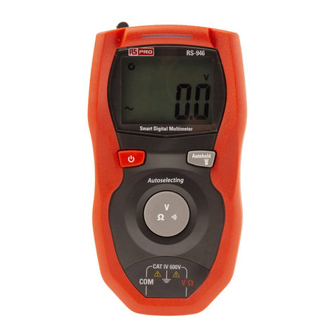
RS PRO S1 User manual

RS PRO
RS PRO IPM 138N User manual

RS PRO
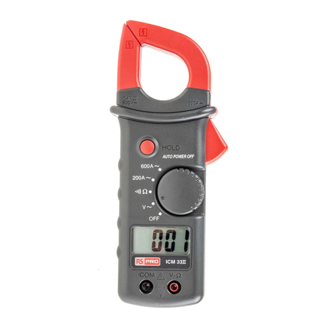
RS PRO ICM33II User manual

RS PRO
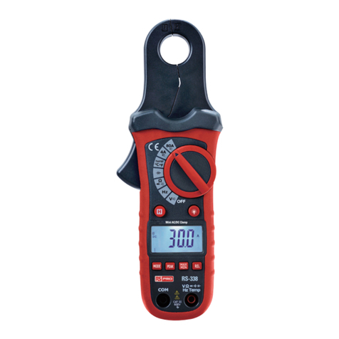
RS PRO RS-338 User manual

RS PRO
RS PRO RS-9963T User manual

RS PRO
RS PRO RS-218 User manual

RS PRO
RS PRO IDM201N User manual

RS PRO
RS PRO IDM 71 User manual

RS PRO
RS PRO IDM93N User manual

RS PRO
RS PRO RS IDM-20 User manual

RS PRO
RS PRO RS-9519BT User manual

RS PRO
RS PRO IDM-8351 User manual

RS PRO
RS PRO RS-9519BT User manual

RS PRO
RS PRO RS-989 User manual

RS PRO
RS PRO ICM 135R User manual

RS PRO
RS PRO ICM 139R User manual