promesstec WTR 190 User manual

Version 2.2.1
promesstec GmbH I Niedersachsenstraße 4 I D-48465 Schüttorf I Tel.:+49 (0)5923/ 90 229 0 I Fax:+49 (0)5923/ 90 229 29
E-Mail: office@promesstec.com I Internet: www.promesstec.com
User manual
Resistance thermometer WTR 190

2
promesstec GmbH I Niedersachsenstraße 4 I D-48465 Schüttorf I Tel.:+49 (0)5923/ 90 229 0 I Fax:+49 (0)5923/ 90 229 29
E-Mail: office@promesstec.com I Internet: www.promesstec.com
Content
1. General................................................................................................................ 4
1.1 Brief description..............................................................................................4
1.2 Overview presentation....................................................................................4
1.3 Drawings, shortcut..........................................................................................5
2. Transport, Packaging, Storage............................................................................ 5
2.1 Transport........................................................................................................5
2.2 Packaging.......................................................................................................6
2.3 Storage...........................................................................................................6
3. Safety instructions.............................................................................................. 6
3.1 Intended use of the product............................................................................6
3.2 Stuff qualification............................................................................................6
3.3 Special hazards..............................................................................................7
4. Starting operation............................................................................................... 8
4.1 Connection .....................................................................................................8
4.2 Mechanical assembly.....................................................................................9
4.3 Electrical assembly.........................................................................................9
5. Putting into operation.......................................................................................... 9
5.1 Configuration DMU 50..................................................................................10
5.1.1 Windows Software „pmtKonfigTool“.......................................................10
5.1.2 pmtKonfigTool - Connection between WTR190-DMU and PC...............11
5.1.3 pmtKonfigTool –read.............................................................................11
5.1.4 pmtKonfigTool –write ............................................................................11
5.1.5 pmtKonfigTool - Factory settings ...........................................................11
5.1.6 Status.....................................................................................................11
5.1.7 Temperature ..........................................................................................12
5.1.8 Display...................................................................................................12
5.1.9 Fault current...........................................................................................12
5.1.10 4..20mA Current output..........................................................................12
5.2 Configuration KMU 100 ................................................................................12
5.2.1 Windows Software „PXU01“...................................................................13
5.2.2 „PXU01“ - Connection between WTR 190-KMU and PC .......................13
5.3 Configuration KMUS 100..............................................................................13
5.3.1 Measuring range selection by DIP-switch..............................................14
5.3.2 Fine adjustment by correction potentiometer.........................................14

3
promesstec GmbH I Niedersachsenstraße 4 I D-48465 Schüttorf I Tel.:+49 (0)5923/ 90 229 0 I Fax:+49 (0)5923/ 90 229 29
E-Mail: office@promesstec.com I Internet: www.promesstec.com
6. Technical specifications.................................................................................... 14
6.1 Technical data DMU 50................................................................................15
6.2 Technical data KMU 100..............................................................................15
6.3 Technical data KMUS 100............................................................................15
6.4 Technical drawing.........................................................................................16
7. Dismounting, Return, Cleaning, Disposal......................................................... 18
7.1 Dismounting .................................................................................................18
7.2 Return...........................................................................................................18
7.3 Cleaning.......................................................................................................18
7.4 Disposal........................................................................................................18
4
promesstec GmbH I Niedersachsenstraße 4 I D-48465 Schüttorf I Tel.:+49 (0)5923/ 90 229 0 I Fax:+49 (0)5923/ 90 229 29
E-Mail: office@promesstec.com I Internet: www.promesstec.com
1. General
1.1 Brief description
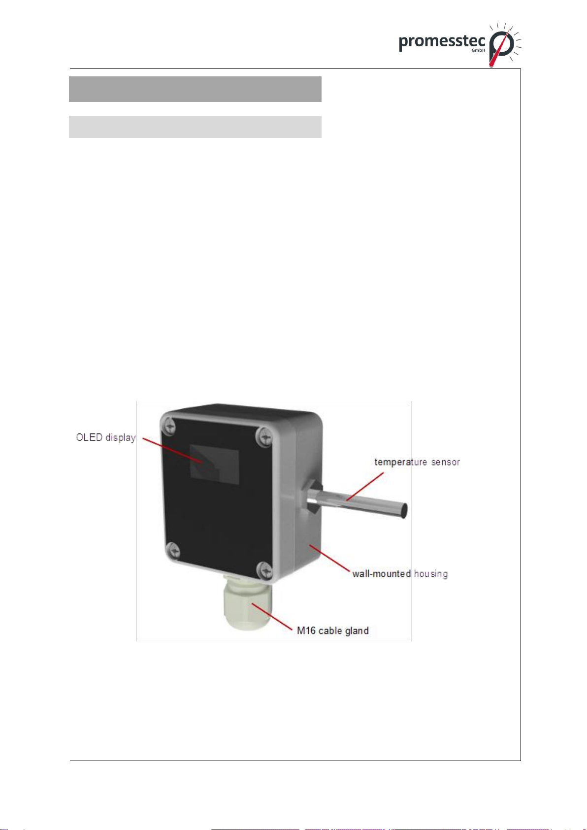
The WTR 190 is a temperature sensor in a wall-mounted housing. This makes it the
right choice for reliably detecting temperatures in rooms or in outdoor areas. Thanks
to the robust polyamide housing, the WTR 190 can also be used without any prob-
lems in blast freezers, deep-freeze warehouses and in aggressive ambient condi-
tions in industry. Optionally, the WTR 190 is available with KMU 100 or KMUS 100.
The KMU100 has a 4..20mA and the KMUS 100 a 0..10V output. The WTR 190 is
also available with DMU 50. The DMU has a 4..20mA output and a high resolution
OLED display.
1.2 Overview presentation
WTR 190-C1-1A2/PT1000-DMU
Resistance thermometer WTR 190
5
promesstec GmbH I Niedersachsenstraße 4 I D-48465 Schüttorf I Tel.:+49 (0)5923/ 90 229 0 I Fax:+49 (0)5923/ 90 229 29
E-Mail: office@promesstec.com I Internet: www.promesstec.com
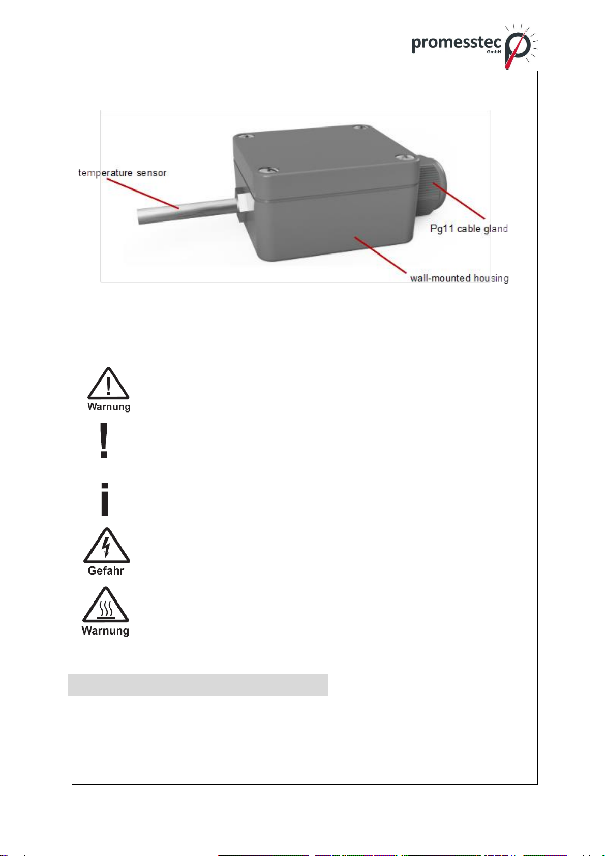
WTR 190-A1-1A3-KMU/ WTR 190-A1-1A3-KMUS
1.3 Drawings, shortcut
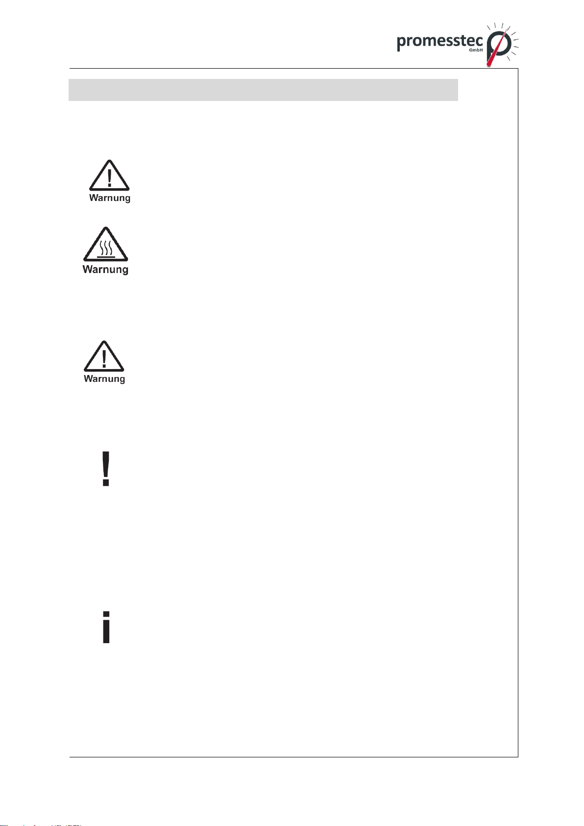
Warning!
A non-observance can cause injuries to persons and/or the demoli-
tion of the device. There can be a dangerous to life.
Attention!
A non-observance can cause a faulty operation of the device or lead
to property damage.
Information!
A non-observance can have influence on the operation of the device
or cause unintentional reactions of the device.
Danger!
When not observing the safety instructions, there is a risk of serious
or fatal injuries caused by electrical power.
Warning!
Possibly a dangerous situation can occur, which results in burns be-
cause of hot surfaces or liquids, if not avoided.
2. Transport, Packaging, Storage
2.1 Transport

6
promesstec GmbH I Niedersachsenstraße 4 I D-48465 Schüttorf I Tel.:+49 (0)5923/ 90 229 0 I Fax:+49 (0)5923/ 90 229 29
E-Mail: office@promesstec.com I Internet: www.promesstec.com
Check the instrument for any damage that may have been caused during transpor-
tation. If, report them immediately. The temperature during transportation and stor-
age of the meter must be within the range of -10 °C to 50 °C.
2.2 Packaging
Do not remove packaging until just before mounting. Keep the packaging as it will
provide optimum protection during transport (e.g. change in installation site, sending
back).
2.3 Storage
For longer term storage avoid the following influences:
1. Direct sunlight or proximity to hot objects
2. Mechanical vibration, mechanical shock (putting it hard down)
3. Soot, vapour, dust and corrosive gases
If possible store the device in its original package or an equivalent one
3. Safety instructions
More important safety instructions can be found in the individual
chapters.
3.1 Intended use of the product
The sensor has been designed and built solely for the intended use described here
and may only be used accordingly. The technical specifications contained in these
operating instructions must be observed. Improper handling or operation of the in-
strument outside of its technical specifications requires the instrument to be taken
out of service immediately and an inspection by the manufacturer. When the instru-
ment is transported from a cold into a warm environment, the formation of conden-
sation may result in the instrument malfunctioning. Before putting it back into oper-
ation, wait for the instrument temperature and the room temperature to equalise.
The manufacturer shall not be liable for claims of any type based on operation con-
trary to the intended use.
3.2 Stuff qualification

7
promesstec GmbH I Niedersachsenstraße 4 I D-48465 Schüttorf I Tel.:+49 (0)5923/ 90 229 0 I Fax:+49 (0)5923/ 90 229 29
E-Mail: office@promesstec.com I Internet: www.promesstec.com
Improper handling can result in considerable injury and damage to
equipment. The activities described in these operating instructions
may only be carried out by skilled stuff who have the qualifications
described below. Keep unqualified stuff away from hazardous areas.
For installation and starting of the flow-meter the stuff has to be familiar with the
relevant regulations and directives of the country and must have the qualification
required. They must have knowledge on measurement and control technology, have
to be acquainted with electric circuits, are capable of carrying out the work described
and can independently recognize potential hazards. Depending on the operation
conditions of the application they have to have the corresponding knowledge, e.g.
of aggressive media.
3.3 Special hazards
For hazardous media such as oxygen, acetylene, flammable or toxic
gases or liquids, refrigeration plants, compressors, etc., in addition to
all standard regulations, the appropriate existing codes or regulations
must also be followed. If you do not observe the appropriate reg-
ulation, serious injuries and/or damage can occur!
A protection from electrostatic discharge (ESD) is required. The
proper use of grounded work surfaces and personal wrist straps is
required when working with exposed circuitry (PCB, printed circuit
boards), in order to prevent static discharge from damaging sensitive
electronic components.
There is a danger of death caused by electric current. Upon contact
with life parts, there is a direct danger of death. Electrical instruments
may only be installed and connected by skilled electrical personnel.
Operation using a defective power supply unit (e.g. short circuit from
the mains voltage to the voltage output) can result in life-threatening
voltages at the instrument.
Residual media in dismounted instruments can result in a risk to per-
sonnel, the environment and equipment. Take sufficient precaution-
ary measures. Do not use this instrument in safety or Emergency
Stop devices. Incorrect use of the instrument can result in injury.
Should a failure occur, aggressive media with extremely high tem-
perature and under high pressure or vacuum may be present at the
instrument.

8
promesstec GmbH I Niedersachsenstraße 4 I D-48465 Schüttorf I Tel.:+49 (0)5923/ 90 229 0 I Fax:+49 (0)5923/ 90 229 29
E-Mail: office@promesstec.com I Internet: www.promesstec.com
4. Starting operation
4.1 Connection
WTR 190 passiv WTR 190 with DMU 50
WTR 190 with KMU 100 WTR 190 with KMUS 100
9
promesstec GmbH I Niedersachsenstraße 4 I D-48465 Schüttorf I Tel.:+49 (0)5923/ 90 229 0 I Fax:+49 (0)5923/ 90 229 29
E-Mail: office@promesstec.com I Internet: www.promesstec.com
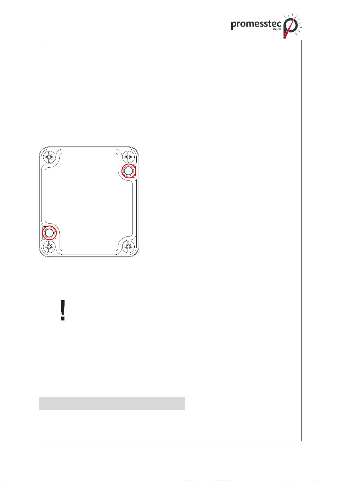
4.2 Mechanical assembly
The WTR 190 is designed as a wall-mounted sensor. Use the holes provided in the
housing for mounting. Use suitable screws that do not destroy the housing. Only by
this we can assure you an optimal measuring point incl. the protection class.
After mounting the sensor, check the tightness of the housing and after installing the
connection cable, check the tightness of the screw connection (cable entry).
Please read the safety instructions on page 11 before assembly and keep these in-
structions for future reference.
1. Loosen the screws of the device cover and
remove the cover.
2. Fasten the device to the wall using suitable
screws through the holes provided in the
housing.
1. Screw the device cover back on.
Provided holes for mounting
4.3 Electrical assembly
The electrical installation must be carried out in a de-energized
state.
- Insert the connection cable into the cable entry (gland). Make sure not to
damage the seal of the cable gland.
- Connect the connecting cables according to your task.
- If a transmitter is used, it can be configured via the respective interfaces.
- Close the housing and switch on the voltage.
5. Putting into operation

10
promesstec GmbH I Niedersachsenstraße 4 I D-48465 Schüttorf I Tel.:+49 (0)5923/ 90 229 0 I Fax:+49 (0)5923/ 90 229 29
E-Mail: office@promesstec.com I Internet: www.promesstec.com
Before switching on the device, it should be checked whether the
sensor has been correctly installed and wired.
5.1 Configuration DMU 50
If the WTR 190 is used with a DMU 50, the settings of the DMU can be read out,
graphically displayed and changed via the Windows software "pmtKonfigTool". In the
following the configuration of the DMU with the "pmtKonfigTool" software is ex-
plained.
5.1.1 Windows Software „pmtKonfigTool“
The current settings of the DMU can be read out and changed via the "pmtKon-
figTool" software. The installation file of the application can be downloaded from the
website www.promesstec.de
The configuration options include the display orientation, the scaling of the current
output and the overflow and underflow behavior of the measuring range. In addition,
the status, the measured value and the current value are read out in real time.

11
promesstec GmbH I Niedersachsenstraße 4 I D-48465 Schüttorf I Tel.:+49 (0)5923/ 90 229 0 I Fax:+49 (0)5923/ 90 229 29
E-Mail: office@promesstec.com I Internet: www.promesstec.com
5.1.2 pmtKonfigTool - Connection between WTR190-DMU and PC
Loosen the cover of the WTR 190 to access the USB C interface of the DMU.
Connect the transmitter to the PC via a commercially available USB C cable.
ATTENTION: WTR 190 restarts after connection via USB! Now start the Windows
software "pmtKonfigTool".
To access the display, the first thing to do is to select the correct COM port. All COM
ports are listed in the "Port" drop-down list. The button updates the drop-down list.
As soon as a connection could be established successfully, the status changes to
"Connected" and the name of the connected device is displayed.
5.1.3 pmtKonfigTool –read
As soon as a connection with the DMU has been established, the settings are read
out and displayed in the software. The status, the temperature and the current value
are continuously updated. In addition, it is possible to press the "Read out" button to
read out and display all settings again.
5.1.4 pmtKonfigTool –write
To change the settings of the DMU, the desired values must be entered in the Win-
dows software and the corresponding options selected. However, the settings are not
applied until the "Write" button has been pressed. If the write operation cannot be
performed successfully, the old settings of the DMU are displayed again.
5.1.5 pmtKonfigTool - Factory settings
By pressing the "Factory settings" button, all parameters and settings are reset to the
delivery state.
Factory settings: Display: 0°
Fault current: activates
MeasuringRangeMin.: -30,0 °C
MeasuringRangeMax.: +80,0°C
5.1.6 Status
In total, the DMU can assume four different statuses, which provide information about
the current loop and the measurement of the current.
Ok: The DMU works flawlessly.
Cable break: There is a cable break in the connected PT 1000.
Underflow: The measured temperature is smaller than the smallest value
which can be can be transmitted with the 4..20mA interface.

12
promesstec GmbH I Niedersachsenstraße 4 I D-48465 Schüttorf I Tel.:+49 (0)5923/ 90 229 0 I Fax:+49 (0)5923/ 90 229 29
E-Mail: office@promesstec.com I Internet: www.promesstec.com
Overflow: The measured temperature is greater than the largest value that
can be transmitted with the can be transmitted with the 4..20mA
interface.
Error evaluation: There is an error in the evaluation of the PT 1000.
5.1.7 Temperature
Under the "Temperature" tab, the currently measured temperature is displayed in real
time.
5.1.8 Display
Under Alignment, the orientation of the display can be rotated by 180°. Thus, the
WTR 190-DMU can also be mounted overhead (cable outlet upwards).
5.1.9 Fault current
Through the check box "Underflow/Overflow", which can be found under "Fault cur-
rent", the overflow and underflow function can be activated or deactivated. If the func-
tion is activated, the DMU will output a current of 20.5mA if the measured tempera-
ture exceeds the maximum temperature of the 4..20mA loop and 3.5mA if the mea-
sured temperature falls below the minimum temperature of the 4..20mA loop. If the
function is disabled, a current of 20mA and 4mA will flow in case of exceeding and
falling below. Regardless of the overflow and underflow function, a current of 21mA
always flows if there is a cable break in the temperature sensor (PT 1000).
5.1.10 4..20mA Current output
Under the tab "4..20mA current output" on the one hand the current of the current
loop is displayed in real time and on the other hand the scaling of the loop is configu-
red. For this purpose, the minimum temperature value for 4mA and the maximum
temperature value for 20mA must be specified.
5.2 Configuration KMU 100
If the WTR 190 is used with a KMU 100, the settings of the KMU can be read out and
changed via the Windows software "PXU01". The parameterization software kit
PXU01 is required for this. This contains the Windows software "PXU01" on CD, an
interface converter (USB adapter) and a plug adapter for the KMU. The configuration
of the KMU with the "PXU01" software is explained below.
13
promesstec GmbH I Niedersachsenstraße 4 I D-48465 Schüttorf I Tel.:+49 (0)5923/ 90 229 0 I Fax:+49 (0)5923/ 90 229 29
E-Mail: office@promesstec.com I Internet: www.promesstec.com
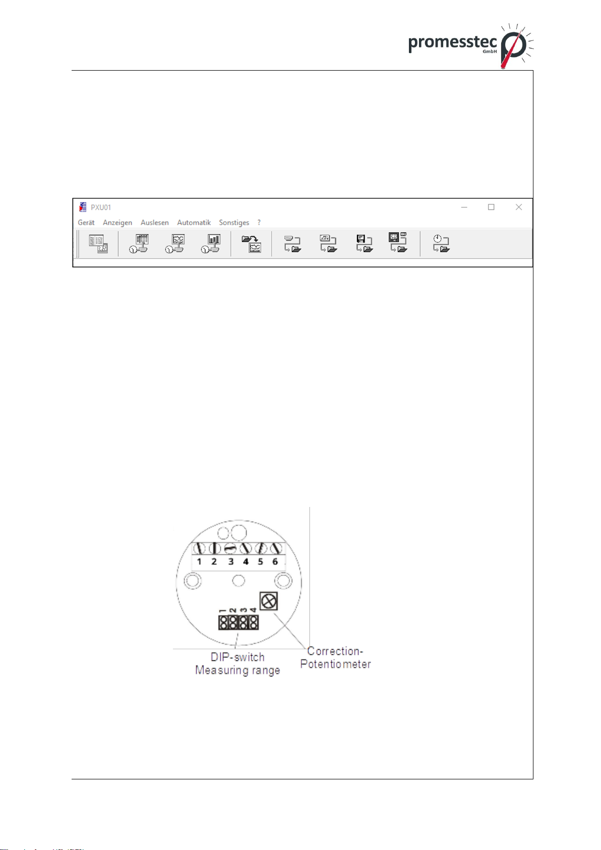
5.2.1 Windows Software „PXU01“
The current settings of the KMU can be read out and changed via the "PXU01" soft-
ware. The installation file of the application is provided via a CD or optionally via a
download link. To obtain the link, contact promesstec GmbH.
The configuration options include scaling of the current output. In addition, the mea-
sured value is read out in real time.
5.2.2 „PXU01“ - Connection between WTR 190-KMU and PC
Loosen the cover of the WTR 190 to access the programming interface of the KMU.
Connect the KMU to the PC via the plug adapter included in the PXU01 paramete-
rization software kit and the interface converter.
To access the device, a connection must first be established in the application. The
settings of the KMU can then be read out and changed.
5.3 Configuration KMUS 100
The KMUS 100 is configured via a potentiometer and four DIP-switches. Configura-
tion on the PC is not necessary.
14
promesstec GmbH I Niedersachsenstraße 4 I D-48465 Schüttorf I Tel.:+49 (0)5923/ 90 229 0 I Fax:+49 (0)5923/ 90 229 29
E-Mail: office@promesstec.com I Internet: www.promesstec.com
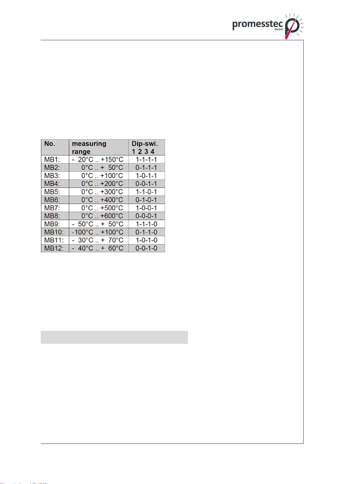
5.3.1 Measuring range selection by DIP-switch
Four DIP-switches can be used to set 12 different measuring ranges. These are lis-
ted in the table below.
The query for the measuring range is permanent. Thus, the voltage supply does not
have to be interrupted after a change of the measuring range. The recognition of the
sensor (Pt 100/Pt 1000) is also done automatically during operation.
Attention: For Pt 1000 only the ranges 1..5 are available.
Jumper = 1: plugged
Jumper = 0: not plugged
5.3.2 Fine adjustment by correction potentiometer
As can be seen in the picture above, the correction potentiometer is located on the
top of the KMUS. This can be used for fine adjustment of the output voltage. A seal
secures the potentiometer against accidental adjustment.
6. Technical specifications
material protective fitting: stainless steel 1.4571 (V4A)
length of sensor: 45 mm other lengths on request
connecting box: plastic polyamide
dimensions: 58 x 64 x 34 mm
protection class: IP 65 according to DIN 60529
operating temperature: -50 °C bis +130 °C
(deviation when using a transmitter)

15
promesstec GmbH I Niedersachsenstraße 4 I D-48465 Schüttorf I Tel.:+49 (0)5923/ 90 229 0 I Fax:+49 (0)5923/ 90 229 29
E-Mail: office@promesstec.com I Internet: www.promesstec.com
6.1 Technical data DMU 50
operating temperature: -30 °C bis +80 °C
operating voltage: UB = 10..35 V DC
electricity demand: 7,3 mA (UB=24V) + 4..20mA output
input: PT1000 2-wire
measuring range max.: -100°C bis +650°C
measuring span min.: 10K
accuracy: <+-0,1% from final value
output: 4..20mA 3-wire active (underflow 3,5mA,overflow
20,5mA)
sensor break: 21mA
standard configuration: 4mA = -50°C, 20mA = 150°C
(more temperature range parameterizable)
max. permissible load: Rmax=[(UB –6V) / 0,021 A] Ω
display: high-resolution OLED display 0,96 Zoll
alignment display: 0° oder 180°
display-digits: 4-digits
displayrange: -99,9 bis +999,9°C
electrical connection: 5x terminal connection 1,5 mm²
configuration: commercial USB Typ C cable (no programming
adapter necessary)
windows application for configuration („pmtKonfig-
Tool“)
6.2 Technical data KMU 100
operating temperature: -40 °C bis +85 °C
operating voltage: UB = 10..35 V DC
electricity demand: 4..20mA output
input: PT100 2-, 3-, 4- wire
measuring range max.: -200°C bis +650°C
Measuring span min.: 10K
accuracy: <+-0,1% from final value
output: 4..20mA 2-wire passive (underflow 3,5mA, overflow
21mA)
sensor break: 22mA
standard configuration: 4mA = -50°C, 20mA = 150°C
(more temperature range parameterizable)
electrical connection: 6x screw terminal 1,5mm²
configuration: programming adapter PXU01
windows application for configuration („PXU01“)
6.3 Technical data KMUS 100
operating temperature: -40 °C bis +85 °C
16
promesstec GmbH I Niedersachsenstraße 4 I D-48465 Schüttorf I Tel.:+49 (0)5923/ 90 229 0 I Fax:+49 (0)5923/ 90 229 29
E-Mail: office@promesstec.com I Internet: www.promesstec.com
operating voltage: UB = 15..35 V DC
electricity demand: max. 10mA
input: PT100/PT1000 2-, 3-, 4-wire
measuring range: 12 measuring ranges, see page 3
accuracy: <+-0,3% from measuring range
output: 0..10V 3-wire
sensor break: >10V
standard configuration: 0V = -20°C, 10V = 150°C
electrical connection: 6x screw terminal 1,5mm²
configuration: DIP-switch (12 different measuring ranges)
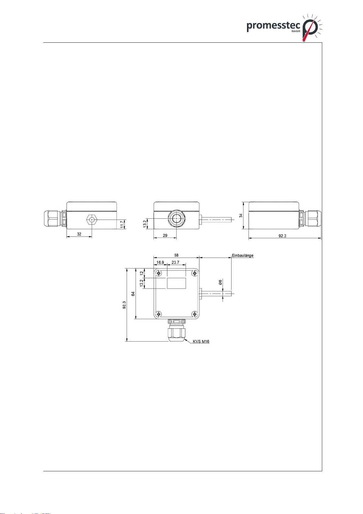
6.4 Technical drawing
WTR 190 mit DMU 50
17
promesstec GmbH I Niedersachsenstraße 4 I D-48465 Schüttorf I Tel.:+49 (0)5923/ 90 229 0 I Fax:+49 (0)5923/ 90 229 29
E-Mail: office@promesstec.com I Internet: www.promesstec.com
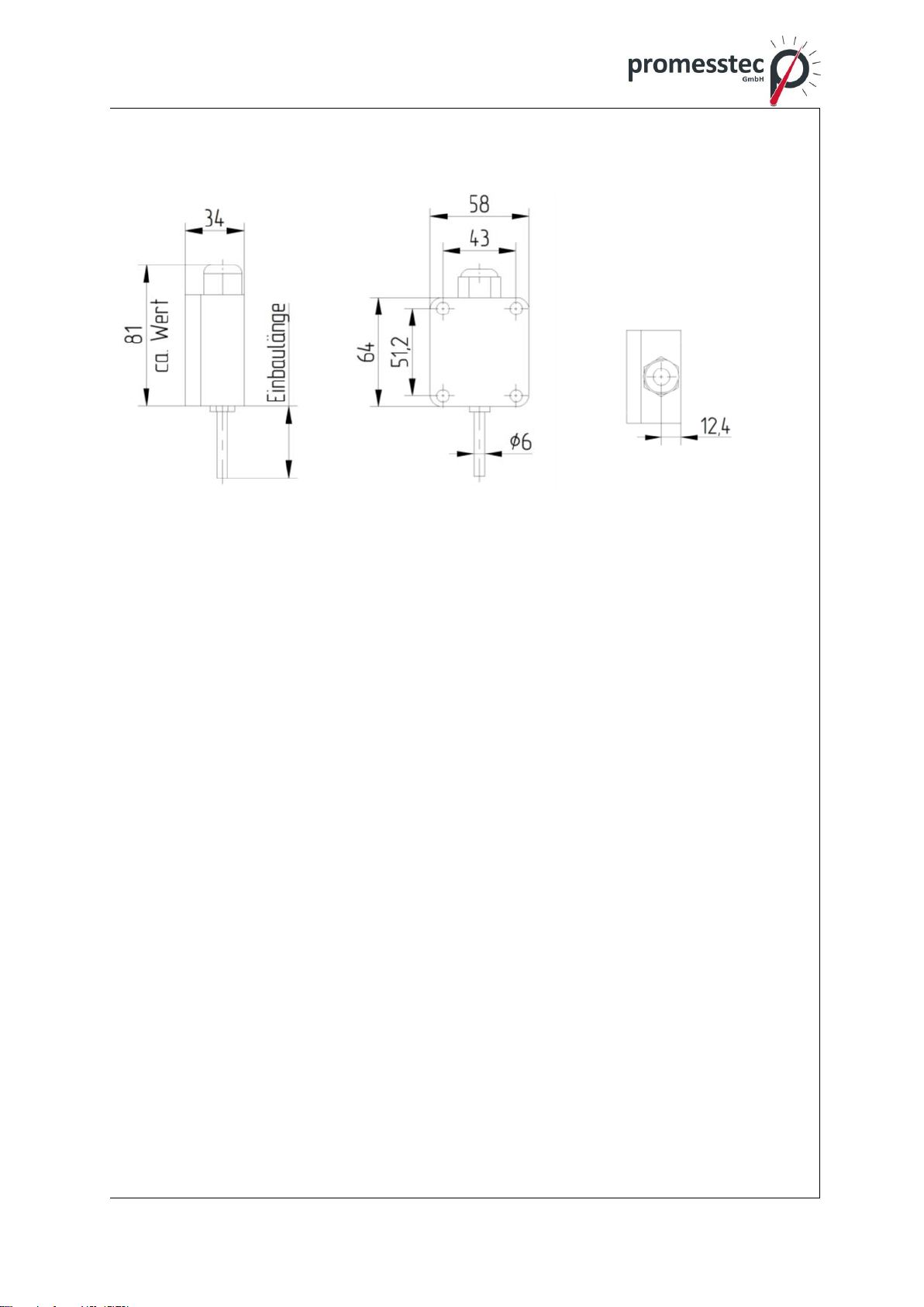
WTR 190 passiv/ WTR 190 with KMU 100 / WTR 190 with KMUS 100
18
promesstec GmbH I Niedersachsenstraße 4 I D-48465 Schüttorf I Tel.:+49 (0)5923/ 90 229 0 I Fax:+49 (0)5923/ 90 229 29
E-Mail: office@promesstec.com I Internet: www.promesstec.com
7. Dismounting, Return, Cleaning, Disposal
7.1 Dismounting
Residual media in dismounted instruments can result in a risk of per-
sonnel, the environment and equipment. Take sufficient precaution-
ary measures.
There is a risk of burns. Let the instrument cool down sufficiently
before dismounting. During dismounting there is a risk of danger-
ously hot pressure media escaping.
Only disconnect the resistance thermometer once the system has
been depressurised.
7.2 Return
When returning the instrument, use the original packaging or a suit-
able package.
To avoid a damage, use for example antistatic plastic film, shock-
absorbent material, a marking as highly sensitive measuring instru-
ment.
7.3 Cleaning
Before cleaning the instrument disconnect the electrical connection.
Clean the instrument with a moist cloth. Electrical connections must
not come into contact with moisture. Wash or clean the dismounted
instrument before returning it in order to protect personnel and the
environment from exposure to residual media.
Residual media in dismounted instruments can result in a risk to
persons, the environment and equipment. Take sufficient precau-
tionary measures.
7.4 Disposal
Dispose instrument components and packaging materials in accord-
ance with the respective waste treatment and disposal regulations
of the region or country to which the sensor is supplied.
Other manuals for WTR 190
1
Table of contents
Other promesstec Thermometer manuals

promesstec
promesstec WTR 290 Series User manual

promesstec
promesstec WTR 280 Series User manual

promesstec
promesstec WTR 270 Series User manual

promesstec
promesstec WTR 190 How to use

promesstec
promesstec WTR 120 User manual

promesstec
promesstec WTR 230 User manual

promesstec
promesstec WTR 230 User manual

promesstec
promesstec WTR 420 Series User manual


