promesstec WTR 120 User manual

Version 3.1.1
promesstec GmbH I Niedersachsenstraße 4 I D-48465 Schüttorf I Tel.:+49 (0)5923/ 90 229 0 I Fax:+49 (0)5923/ 90 229 29
E-Mail: office@promesstec.com I Internet: www.promesstec.com
User manual
Resistance thermometer WTR 120

2
promesstec GmbH I Niedersachsenstraße 4 I D-48465 Schüttorf I Tel.:+49 (0)5923/ 90 229 0 I Fax:+49 (0)5923/ 90 229 29
E-Mail: office@promesstec.com I Internet: www.promesstec.com
General
1. General................................................................................................................ 4
1.1 Description of measuring principle..................................................................4
1.2 Overview presentation....................................................................................4
1.3 Drawings, shortcut..........................................................................................5
2. Transport, Packaging, Storage........................................................................... 5
2.1 Transport........................................................................................................5
2.2 Packaging.......................................................................................................5
2.3 Storage...........................................................................................................5
3. Safety instructions............................................................................................... 6
3.1 Intended use of the product............................................................................6
3.2 Stuff qualification............................................................................................6
3.3 Special hazards..............................................................................................6
4. Starting operation............................................................................................... 8
4.1 Connection WTR 120 passive (ceramic base) ...............................................8
4.2 Connection WTR 120 with measuring transducer ..........................................8
4.3 Connection WTR 120 with M12 plug..............................................................9
4.4 Mechanical assembly.....................................................................................9
4.5 Electrical assembly.........................................................................................9
5. Operation.......................................................................................................... 10
5.1 Configuration DMU 100................................................................................10
5.1.1 Windows Software „pmtKonfigTool“.......................................................10
5.1.2 pmtKonfigTool - connection between WTR 120-DMU and PC...............11
5.1.3 pmtKonfigTool –read.............................................................................11
5.1.4 pmtKonfigTool –write ............................................................................11
5.1.5 pmtKonfigTool –factory settings............................................................11
5.1.6 Status.....................................................................................................12
5.1.7 Temperature ..........................................................................................12
5.1.8 Display...................................................................................................12
5.1.9 Fault current...........................................................................................12
5.1.10 4..20mA current output ..........................................................................12
5.2 Configuration KMU 100 ................................................................................13
5.2.1 Windows Software „PXU01“...................................................................13
5.2.2 „PXU01“ - connection between WTR 120-KMU and PC........................13
5.3 Configuration KMUS 100..............................................................................14

3
promesstec GmbH I Niedersachsenstraße 4 I D-48465 Schüttorf I Tel.:+49 (0)5923/ 90 229 0 I Fax:+49 (0)5923/ 90 229 29
E-Mail: office@promesstec.com I Internet: www.promesstec.com
5.3.1 Measuring range selection by DIP-switch..............................................14
5.3.2 Fine adjustment by correction potentiometer.........................................15
6. Technical specifications.................................................................................... 15
6.1 Technical data DMU 100..............................................................................15
6.2 Technical data KMU 100..............................................................................16
6.3 Technical data KMUS 100............................................................................16
6.4 Technical drawing.........................................................................................17
7. Dismounting, return, cleaning, disposal............................................................ 19
7.1 Dismounting .................................................................................................19
7.2 Return...........................................................................................................19
7.3 Cleaning.......................................................................................................19
7.4 Disposal........................................................................................................19
4
promesstec GmbH I Niedersachsenstraße 4 I D-48465 Schüttorf I Tel.:+49 (0)5923/ 90 229 0 I Fax:+49 (0)5923/ 90 229 29
E-Mail: office@promesstec.com I Internet: www.promesstec.com
1. General
1.1 Description of measuring principle
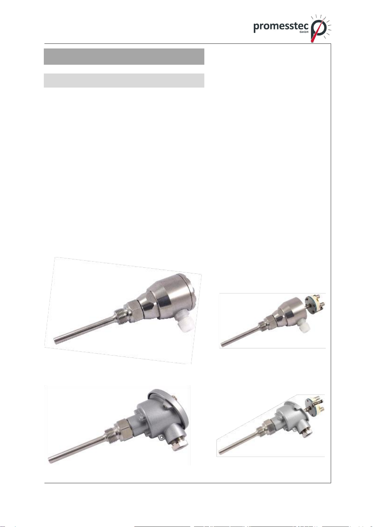
The WTR 120 is a temperature sensor for use in liquid and gaseous media. With the
thread as a process connection, it can be easily integrated into many industrial appli-
cations. The simple replacement of the measuring insert makes this sensor ideal for
use in closed processes. High-quality materials give this sensor very high long-term
stability. The WTR 120 is available with various connection heads made of aluminum
or stainless steel. The WTR 120 is also available passively or with the following mea-
suring transducers:
- Digital measuring transducer DMU 100 (4..20mA 3-wire/OLED display)
- Head transmitter KMU100 (4..20mA 2-wire)
- Head transmitter KMUS100 (0..10V 3-wire)
1.2 Overview presentation
WTR 120-5-B-1A3-KMU
WTR 120-1-B-1A3-KMU
Resistance thermometer WTR 120
5
promesstec GmbH I Niedersachsenstraße 4 I D-48465 Schüttorf I Tel.:+49 (0)5923/ 90 229 0 I Fax:+49 (0)5923/ 90 229 29
E-Mail: office@promesstec.com I Internet: www.promesstec.com
1.3 Drawings, shortcut
Warning!
A non-observance can cause injuries to persons and/or the demoli-
tion of the device. There can be a dangerous to life.
Attention!
A non-observance can cause a faulty operation of the device or lead
to property damage.
Information!
A non-observance can have influence on the operation of the device
or cause unintentional reactions of the device.
Danger!
When not observing the safety instructions, there is a risk of serious
or fatal injuries caused by electrical power.
Warning!
Possibly a dangerous situation can occur, which results in burns be-
cause of hot surfaces or liquids, if not avoided.
2. Transport, Packaging, Storage
2.1 Transport
Check the instrument for any damage that may have been caused during transpor-
tation. If, report them immediately. The temperature during transportation and stor-
age of the meter must be within the range of -10 °C to 50 °C.
2.2 Packaging
Do not remove packaging until just before mounting. Keep the packaging as it will
provide optimum protection during transport (e.g. change in installation site, send-
ing back).
2.3 Storage
For longer term storage avoid the following influences:
1. Direct sunlight or proximity to hot objects
2. Mechanical vibration, mechanical shock (putting it hard down)
3. Soot, vapour, dust and corrosive gases

6
promesstec GmbH I Niedersachsenstraße 4 I D-48465 Schüttorf I Tel.:+49 (0)5923/ 90 229 0 I Fax:+49 (0)5923/ 90 229 29
E-Mail: office@promesstec.com I Internet: www.promesstec.com
If possible store the device in its original package or an equivalent one.
3. Safety instructions
More important safety instructions can be found in the individual
chapters.
3.1 Intended use of the product
The sensor has been designed and built solely for the intended use described here
and may only be used accordingly. The technical specifications contained in these
operating instructions must be observed. Improper handling or operation of the in-
strument outside of its technical specifications requires the instrument to be taken
out of service immediately and an inspection by the manufacturer. When the instru-
ment is transported from a cold into a warm environment, the formation of conden-
sation may result in the instrument malfunctioning. Before putting it back into ope-
ration, wait for the instrument temperature and the room temperature to equalise.
The manufacturer shall not be liable for claims of any type based on operation
contrary to the intended use.
3.2 Stuff qualification
Improper handling can result in considerable injury and damage to
equipment. The activities described in these operating instructions
may only be carried out by skilled stuff who have the qualifications
described below. Keep unqualified stuff away from hazardous areas.
For installation and starting of the flow-meter the stuff has to be familiar with the
relevant regulations and directives of the country and must have the qualification
required. They must have knowledge on measurement and control technology, have
to be acquainted with electric circuits, are capable of carrying out the work described
and can independently recognize potential hazards. Depending on the operation
conditions of the application they have to have the corresponding knowledge, e.g.
of aggressive media.
3.3 Special hazards
7
promesstec GmbH I Niedersachsenstraße 4 I D-48465 Schüttorf I Tel.:+49 (0)5923/ 90 229 0 I Fax:+49 (0)5923/ 90 229 29
E-Mail: office@promesstec.com I Internet: www.promesstec.com
For hazardous media such as oxygen, acetylene, flammable or toxic
gases or liquids, refrigeration plants, compressors, etc., in addition to
all standard regulations, the appropriate existing codes or regulations
must also be followed. If you do not observe the appropriate reg-
ulation, serious injuries and/or damage can occur!
A protection from electrostatic discharge (ESD) is required. The
proper use of grounded work surfaces and personal wrist straps is
required when working with exposed circuitry (PCB, printed circuit
boards), in order to prevent static discharge from damaging sensitive
electronic components.
There is a danger of death caused by electric current. Upon contact
with life parts, there is a direct danger of death. Electrical instruments
may only be installed and connected by skilled electrical personnel.
Operation using a defective power supply unit (e.g. short circuit from
the mains voltage to the voltage output) can result in life-threatening
voltages at the instrument.
Residual media in dismounted instruments can result in a risk to per-
sonnel, the environment and equipment. Take sufficient precaution-
ary measures. Do not use this instrument in safety or Emergency
Stop devices. Incorrect use of the instrument can result in injury.
Should a failure occur, aggressive media with extremely high tem-
perature and under high pressure or vacuum may be present at the
instrument.

8
promesstec GmbH I Niedersachsenstraße 4 I D-48465 Schüttorf I Tel.:+49 (0)5923/ 90 229 0 I Fax:+49 (0)5923/ 90 229 29
E-Mail: office@promesstec.com I Internet: www.promesstec.com
4. Starting operation
4.1 Connection WTR 120 passive (ceramic base)
4.2 Connection WTR 120 with measuring transducer
WTR 120 with KMU 100 WTR 120 with DMU 100 WTR 120 with KMUS 100
d
DIP-switch
Correction po-
tentiometer

Version 3.1.1
promesstec GmbH I Niedersachsenstraße 4 I D-48465 Schüttorf I Tel.:+49 (0)5923/ 90 229 0 I Fax:+49 (0)5923/ 90 229 29
E-Mail: office@promesstec.com I Internet: www.promesstec.com
4.3 Connection WTR 120 with M12 plug
4.4 Mechanical assembly
For adaptation in your process, only use the weld-in sockets and process
connections from promesstec. This is the only way we can promise you an op-
timal measuring point.
After installing the sensor, check the tightness of the measuring point
4.5 Electrical assembly
The electrical installation must be carried out in a de-energized state.
Connection with cable gland:
Insert the connection cable into the cable entry (screw connection). Be careful
not to damage the seal on the cable gland.
Connect the connecting cables according to your circuit task.
You can parameterize the device via the interface (DMU 100, KMU 100 or
KMUS 100 measuring transducer option).
Close the case and turn on the power.
Connection with M12 connector:
Screw the M12 socket onto the plug on the promesstec by hand
Sensor. Assembly is carried out without tools.
When installing the connection cable, ensure that it is firm and form-fitting
Connection of both components. The permissible tightening torque can be
found in the data sheet of the respective connection cable.

Version 3.1.1
promesstec GmbH I Niedersachsenstraße 4 I D-48465 Schüttorf I Tel.:+49 (0)5923/ 90 229 0 I Fax:+49 (0)5923/ 90 229 29
E-Mail: office@promesstec.com I Internet: www.promesstec.com
5. Operation
Before switching on the device, it should be checked whether the sen-
sor has been correctly installed and wired.
5.1 Configuration DMU 100
If the WTR 120 is used with a DMU100, the DMU settings can be read out, graphi-
cally displayed and changed using the Windows software “pmtKonfigTool”. The follo-
wing explains how to configure the DMU with the “pmt-KonfigTool” software.
5.1.1 Windows Software „pmtKonfigTool“
The current settings of the DMU can be read out and changed via the "pmtKon-fig-
Tool" software. The installation file of the application can be downloaded from the
website www.promesstec.de

11
promesstec GmbH I Niedersachsenstraße 4 I D-48465 Schüttorf I Tel.:+49 (0)5923/ 90 229 0 I Fax:+49 (0)5923/ 90 229 29
E-Mail: office@promesstec.com I Internet: www.promesstec.com
The configuration options include the display orientation, the scaling of the current
output and the overflow and underflow behavior of the measuring range. In addition,
the status, the measured value and the current value are read out in real time.
5.1.2 pmtKonfigTool - connection between WTR 120-DMU and PC
Loosen the cover of the WTR 120 to access the USB C interface of the DMU.
Connect the transmitter to the PC using a standard USB C cable.
ATTENTION: WTR 120 restarts after connection via USB! Now start the Windows
software “pmtKonfigTool”.
To access the display, the correct COM port must first be selected. All COM ports are
listed in the “Port” drop-down list. The button updates the drop-down list. As soon as
a connection has been successfully established, the status changes to “Connected”
and the name of the connected device is displayed.
5.1.3 pmtKonfigTool –read
As soon as a connection to the DMU has been established, the settings are read and
displayed in the software. The status, temperature and current value are conti-
nuously updated. It is also possible to press the “Read” button to read and display all
settings again.
5.1.4 pmtKonfigTool –write
To change the DMU settings, the desired values must be entered into the Windows
software and the appropriate options selected. However, the settings are only ap-
plied once the “Write” button has been pressed. If the writing process cannot be car-
ried out successfully, the old DMU settings will be displayed again.
5.1.5 pmtKonfigTool –factory settings
By pressing the "Factory settings" button, all parameters and settings are reset to the
delivery state.
Factory settings: Display: 0°
Fault current: activated
Measuring range Min.: - 50.0 °C
Measuring range Max.: +150.0 °C

12
promesstec GmbH I Niedersachsenstraße 4 I D-48465 Schüttorf I Tel.:+49 (0)5923/ 90 229 0 I Fax:+49 (0)5923/ 90 229 29
E-Mail: office@promesstec.com I Internet: www.promesstec.com
5.1.6 Status
Overall, the DMU can assume four different statuses, which provide information
about the current loop and the measurement of the current.
Ok: the DMU is working properly.
Cable break: there is a cable break in the connected PT1000.
Underflow: the measured temperature is smaller than the smallest value that
can be transmitted with the 4..20mA interface.
Overflow: the measured temperature is greater than the largest value that
can be transmitted with the 4..20mA interface.
Error evaluation: there is an error in the evaluation of the PT1000.
5.1.7 Temperature
Under the "Temperature" tab, the currently measured temperature is displayed in real
time.
5.1.8 Display
Under Orientation, the orientation of the display can be rotated by 180°. The WTR
120-DMU can also be mounted overhead (cable outlet upwards).
5.1.9 Fault current
The overflow and underflow function can be activated or deactivated using the “Un-
derflow/Overflow” check box, which can be found under “Error current”. If the func-
tion has been activated, the DMU outputs a current of 20.5mA when the measured
temperature exceeds the maximum temperature of the 4..20mA loop and 3.5mA
when the measured temperature falls below the minimum temperature of the
4..20mA loop. If the function is deactivated, a current of 20mA and 4mA flows in the
event of overshooting or undershooting. Regardless of the overflow and underflow
function, a current of 21mA always flows if there is a cable break in the temperature
sensor (PT1000).
5.1.10 4..20mA current output
Under the “4..20mA current output” tab, the current of the current loop is displayed in
real time and the scaling of the loop is configured. To do this, the minimum tempera-
ture value for 4mA and the maximum temperature value for 20mA must be specified.
13
promesstec GmbH I Niedersachsenstraße 4 I D-48465 Schüttorf I Tel.:+49 (0)5923/ 90 229 0 I Fax:+49 (0)5923/ 90 229 29
E-Mail: office@promesstec.com I Internet: www.promesstec.com
5.2 Configuration KMU 100
If the WTR 120 is used with a KMU 100, the settings of the KMU can be read and
changed using the Windows software “PXU01”. The PXU01 parameterization soft-
ware kit is required for this. This contains the Windows software “PXU01” on CD, an
interface converter (USB adapter) and a plug adapter for the SME. The following ex-
plains the configuration of the SME with the “PXU01” software.
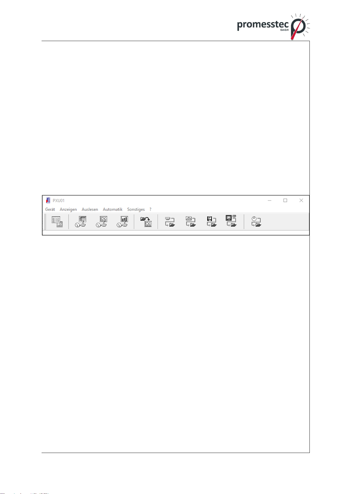
5.2.1 Windows Software „PXU01“
The current settings of the KMU can be read and changed using the “PXU01” soft-
ware. The application installation file is provided via a CD or optionally via a down-
load link. To receive the link, contact promesstec GmbH.
The configuration options include, among other things, scaling the current output. In
addition, the measured value is read out in real time.
5.2.2 „PXU01“ - connection between WTR 120-KMU and PC
Loosen the cover of the WTR 120 to access the programming interface of the KMU.
Connect the SME to the PC using the plug adapter and interface converter included
in the PXU01 parameterization software kit.
In order to access the device, a connection must first be established in the applica-
tion. The SME’s settings can then be read and changed.
14
promesstec GmbH I Niedersachsenstraße 4 I D-48465 Schüttorf I Tel.:+49 (0)5923/ 90 229 0 I Fax:+49 (0)5923/ 90 229 29
E-Mail: office@promesstec.com I Internet: www.promesstec.com
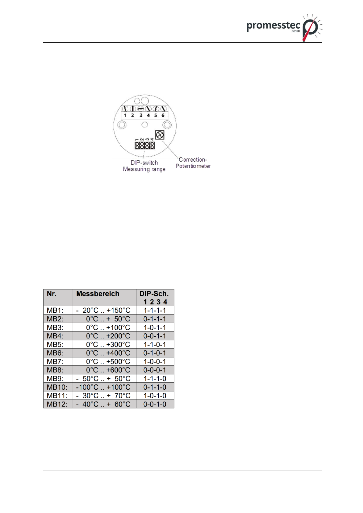
5.3 Configuration KMUS 100
The KMUS 100 is configured using a potentiometer and four DIP switches. Configu-
ration on the PC is not necessary.
5.3.1 Measuring range selection by DIP-switch
Four DIP-switches can be used to set 12 different measuring ranges. These are lis-
ted in the table below.
The query for the measuring range is permanent. Thus, the voltage supply does not
have to be interrupted after a change of the measuring range. The recognition of the
sensor (Pt 100/Pt 1000) is also done automatically during operation.
Attention: For Pt 1000 only the ranges 1..5 are available.
Jumper = 1: plugged
Jumper = 0: not plugged

15
promesstec GmbH I Niedersachsenstraße 4 I D-48465 Schüttorf I Tel.:+49 (0)5923/ 90 229 0 I Fax:+49 (0)5923/ 90 229 29
E-Mail: office@promesstec.com I Internet: www.promesstec.com
5.3.2 Fine adjustment by correction potentiometer
As can be seen in the image above, the correction potentiometer is located on the
upper side of the KMUS. This can be used to fine-tune the output voltage. A seal
secures the potentiometer against accidental adjustment.
6. Technical specifications
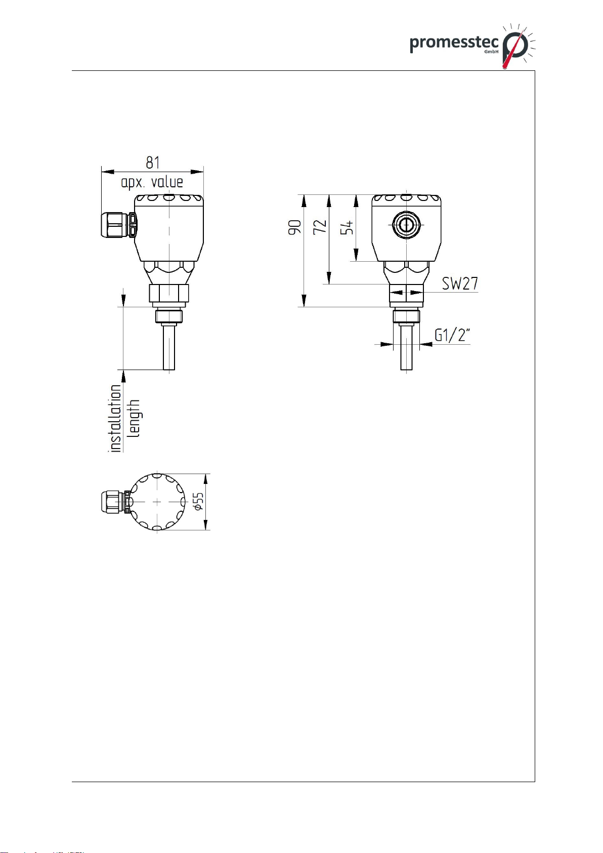
Protective fitting made of stainless steel 1.4571
Diameter 9 x 1 mm, other diameters on request
Process connection thread G 1/2“A, others on request
Operating temperature: -50 °C to +400 °C (extended ranges on request)
Deviation in operating temperature when using a transmitter
6.1 Technical data DMU 100
Operating temperature: -30 °C..+70 °C
Operating voltage: UB = 10..35 V DC
Current requirement: 7.3 mA (UB=24V) + 4..20mA output
Input: PT1000 2-wire
Measuring range max.: -100°C..+650°C
Measuring span min.: 10 K
Measuring deviation: <+-0.1% of the final value
Output: 4..20mA 3-wire (underflow 3.5mA, overflow
20.5mA)
Sensor break: 21mA
Standard configuration: 4mA = -50°C, 20mA = 150°C
(wide temperature range can be parameterized)
Max. permissible load: Rmax = [(UB –6V) / 0.021 A] Ω
Display: high-resolution OLED display 0.96 inches
Orientation display: 0° or 180°
Display digits: 4 digits
Display range: -99.9 to +999.9°C
Configuration interface: USB Type C
Electrical connection: 6 screw terminals 1.5mm²
Configuration: Commercially available USB C cable (no program-
ming adapter necessary)
Windows application for configuration (“pmt-Konfig-
Tool”)

16
promesstec GmbH I Niedersachsenstraße 4 I D-48465 Schüttorf I Tel.:+49 (0)5923/ 90 229 0 I Fax:+49 (0)5923/ 90 229 29
E-Mail: office@promesstec.com I Internet: www.promesstec.com
6.2 Technical data KMU 100
Operating temperature: -40 °C..+85 °C
Operating voltage: UB = 10..35VDC
Current requirement: 4..20mA output
Input: PT100 2, 3, 4 wire
Measuring range max.. -200°C..+650°C
Measuring span min.: 10 K
Measuring deviation: <+-0.1% of the final value
Output: 4-20mA (underflow 3.5mA, overflow 20.5mA)
Sensor break: 21mA
Standard configuration. 4mA = -50°C, 20mA = 150°C (wide temperature
range can be parameterized)
Ambient temperature: Operating temperature -40°C..85°C
Electrical connection: 6x screw terminals 1.5mm²
Configuration: PXU01 programming adapter
Windows application for configuration (“PXU01”)
6.3 Technical data KMUS 100
Operating temperature: -40 °C ..+85 °C
Operating voltage: UB = 15..35 V DC
Current requirement: max. 10mA
Input: PT100/PT1000 2, 3, 4 wire
Measuring range: 12 measuring ranges, see page 3
Measuring deviation: <+-0.3% of measuring range
Output: 0..10V 3-wire
Sensor break: >10V
Standard configuration: 0V = -20°C, 10V = 150°C
Electrical connection: 5x terminal connection 1.5 mm²
Configuration: DIP switch (12 different measuring ranges)
17
promesstec GmbH I Niedersachsenstraße 4 I D-48465 Schüttorf I Tel.:+49 (0)5923/ 90 229 0 I Fax:+49 (0)5923/ 90 229 29
E-Mail: office@promesstec.com I Internet: www.promesstec.com
6.4 Technical drawing
WTR 120 stainless steel connection head

18
promesstec GmbH I Niedersachsenstraße 4 I D-48465 Schüttorf I Tel.:+49 (0)5923/ 90 229 0 I Fax:+49 (0)5923/ 90 229 29
E-Mail: office@promesstec.com I Internet: www.promesstec.com
WTR 120 aluminum connection head

19
promesstec GmbH I Niedersachsenstraße 4 I D-48465 Schüttorf I Tel.:+49 (0)5923/ 90 229 0 I Fax:+49 (0)5923/ 90 229 29
E-Mail: office@promesstec.com I Internet: www.promesstec.com
7. Dismounting, return, cleaning, disposal
7.1 Dismounting
Residual media in dismounted instruments can result in a risk of
personnel, the environment and equipment. Take sufficient precau-
tionary measures.
There is a risk of burns. Let the instrument cool down sufficiently
before dismounting. During dismounting there is a risk of dange-
rously hot pressure media escaping.
Only disconnect the resistance thermometer once the system has
been depressurised.
7.2 Return
To return the device, use the original packaging or something similar. To protect
against damage, e.g. antistatic film, insulating material, marking can be used as a
sensitive measuring device. Find out about the return process at www.promesstec.de
and note the “return form” or contact our product support:
promestec GmbH
Niedersachsenstraße 4
48465 Schüttorf
Tel.: 05923 902290
7.3 Cleaning
Before cleaning the instrument disconnect the electrical connec-
tion. Clean the instrument with a moist cloth. Electrical connections
must not come into contact with moisture. Wash or clean the
dismounted instrument before returning it in order to protect per-
sonnel and the environment from exposure to residual media.
Residual media in dismounted instruments can result in a risk to
persons, the environment and equipment. Take sufficient precauti-
onary measures.
7.4 Disposal This device is not subject to the WEEE Directive 2012/19/EU and
the corresponding national laws. Take the device directly to a spe-
cialized recycling company and do not use the municipal collection
points. These may only be used for privately used products in ac-
cordance with theWEEE directive. Proper disposal avoids negative

20
promesstec GmbH I Niedersachsenstraße 4 I D-48465 Schüttorf I Tel.:+49 (0)5923/ 90 229 0 I Fax:+49 (0)5923/ 90 229 29
E-Mail: office@promesstec.com I Internet: www.promesstec.com
effects on people and the environment and enables valuable raw
materials to be reused.
This manual suits for next models
2
Table of contents
Other promesstec Thermometer manuals

promesstec
promesstec WTR 270 Series User manual

promesstec
promesstec WTR 190 User manual

promesstec
promesstec WTR 420 Series User manual

promesstec
promesstec WTR 290 Series User manual

promesstec
promesstec WTR 190 How to use

promesstec
promesstec WTR 230 User manual

promesstec
promesstec WTR 280 Series User manual

promesstec
promesstec WTR 230 User manual


