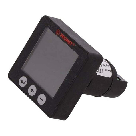
Promet MD22-TFT User manual

www.sn-promet.pl
Spółdzielnia Niewidomych PROMET 41-200Sosnowiec,ul.Lipowa11
Centrala:tel+48222698100,Sekretariat:tel.+48 32 269 81 02, Dział Obsługi Klienta: tel. +48 32 269 81 81,
Strona|1
Panel indicators with 1,44” TFT display
MD22-TFT
Pt-100 Thermometer
User Manual
no: IO-W_MD22-TFT-T (eng)

www.sn-promet.pl
Spółdzielnia Niewidomych PROMET 41-200Sosnowiec,ul.Lipowa11
Centrala:tel+48222698100,Sekretariat:tel.+48 32 269 81 02, Dział Obsługi Klienta: tel. +48 32 269 81 81,
Strona|2
1. Characteristics of the MD22-TFT series
The MD22-TFT indicators are an exemplary development of the MD22 series so far containing only
signal lamps, LED indicators and buzzers.
Main characteristics of all MD22-TFT indicators:
−visualization of the input size or signal on the 1,44” TFT
−assembly in a standard Ø 22 hole
−supply voltage –24V DC (10÷32 V) or 24V AC (±10%)
This manual contains instructions for the standardized signals indicator 0-10V / 4-20mA MD22-TFT- IU.
General appearance for all types of indicators don’t differ. Aside from markings of the terminal and
functions of the control buttons.
Appearance and dimensions of the MD22-TFT are presented on Fig. 1.
Fig. 1. Appearance and dimensions
1.1. Characteristics of MD22-TFT-T digital thermometer.
The indicator in the MD22-TFT-T version is a digital temperature meter cooperating with the PT100
sensor (not included) intended mainly for monitoring the temperature of industrial equipment,
temperature in switchgear cabinets, etc. The range of measured resistance corresponds to the
temperature range -200 ÷ 800 ° C . The actual temperature range depends on the construction of the

www.sn-promet.pl
Spółdzielnia Niewidomych PROMET 41-200Sosnowiec,ul.Lipowa11
Centrala:tel+48222698100,Sekretariat:tel.+48 32 269 81 02, Dział Obsługi Klienta: tel. +48 32 269 81 81,
Strona|3
Pt100 sensor used. Basic error of measurement ± 2 ° C for the entire temperature range measured -
200 ÷ 800 ºC, (does not take into account the error of the sensor).
PT100 sensor connection can be done by two- or three-wire depending on the design of the sensor.
The display is three-digit without a decimal point (accuracy to full degrees). In addition, a bar graph is
displayed on the screen (in the form of a horizontal beam of variable length) giving rough information
about the measured temperature, but readable from a larger distance than a digital reading.
The thermometer has upper and lower alarm outputs..
2. Basic requirements and safety of use.
Meaning of symbols:
−it is particularly important to read before connecting the indicator. Failure to comply
with the remarks marked with this symbol may cause damage to the indicator or the
occurrence of hazards.
−means relevant parts of the description regarding the specific characteristics of the
indicator. In terms of operational safety, the indicator meets the requirements of the
PN-EN 61010-1 standard.
2.1. Security considerations:
.
−The installation and connection of the indicator should be carried out by qualified
personnel,
−All available protection requirements should be taken into account,
−Before switching on the power supply, check the correctness of electrical connections,
−Before disassembling the indicator from the board, it should be disconnected
from the power supply.
3. Installation
.
3.1. Mechanical fastening
The indicator is designed for mounting in a standard Ø22.5mm hole with a positioning cut-out at the
top. Mounting the indicator to the board boils down to inserting the body into the prepared hole and
screwing it from the rear with the fixing nut.
3.2. Electrical connections
The meter is equipped with six screw terminals. The maximum cross-sectionof wires - 0.5mm2.
It is recommended to solder or use cable ends with solder ends.
Terminal designations and electrical connections are shown in Fig.2.
The Pt100 temperature sensor can be connected in a three-wire connection as shown in figure 2
or a two-wire connection. In the case of a two-wire connection, the Pt100 sensor must be connected
between the "In" and "GND" terminals. The "In1" terminal can be left free or (better) connected
to "GND".
For the three-wire connection, equal resistances of the wires connected to the "In" and "GND"
terminals, supplying the current to the Pt100 sensor are assumed. The wire connected to the "In1"
input can be treated as a current less one (the resistance does not have a significant effect on the
measurement result).

www.sn-promet.pl
Spółdzielnia Niewidomych PROMET 41-200Sosnowiec,ul.Lipowa11
Centrala:tel+48222698100,Sekretariat:tel.+48 32 269 81 02, Dział Obsługi Klienta: tel. +48 32 269 81 81,
Strona|4
The alarm outputs Al L and Al H are of the open NPN collector type.
Output transistors: Umax = 100V Imax = 800mA.
Fig. 2 Connections
4. Operation
After the power is turned on, a text message is displayed containing a summary of all current
settings, namely:
−MD22-TFT-T (mark)
−In (type of entry) factory-set.2-wire
−Max (max of range) factory-set.100 ºC
−Min (min of range for barg.) factory-set.000 ºC
−Al H (overflow alarm - upper) factory-set.80 ºC (ON)
−Al L (overflow alarm - lower) factory-set.10 ºC (ON)
After approx. 4 seconds, the device switches to normal operation mode, with the settings in
accordance with the list. The list can be recalled from the normal mode by pressing (shortly)
the "-"or "+".
4.1. Screen view during normal operation.
Figure 3 shows a view of the screen.
Fig. 3 normal view
The following elements are visible on the screen:

www.sn-promet.pl
Spółdzielnia Niewidomych PROMET 41-200Sosnowiec,ul.Lipowa11
Centrala:tel+48222698100,Sekretariat:tel.+48 32 269 81 02, Dział Obsługi Klienta: tel. +48 32 269 81 81,
Strona|5
−At the top of the screen, in the first line of text, the lower alarm (blue) and upper (red) alarms
are displayed. If any of the alarms has been programmed as disabled - instead of the value,
the symbol "OFF" is displayed (for example in Fig. 3 for the lower alarm).
−Below, directly above the bargraph strip, the temperature values entered during programming
are displayed in yellow, equal to the minimum and maximum range for the bargraph.
−A bargraph is displayed in the middle of the screen in the form of a yellow horizontal bar.
Zero strip length - measured temperature less than or equal to the minimum range for the
bargraph introduced during programming. The maximum length of the bar (the entire width
of the screen) - a temperature higher or equal to the maximum of the range.
note:
Bar graph is only rough information about the measured temperature, but it is readable from a
greater distance than the digital display.
−Below the bar graph, the measured temperature is displayed in digital form (white colour)
with units (ºC, cyan colour). Activation of alarms is signalled by the change in the colour
temperature display from white to blue (temperature below the lower threshold) or to the
red one (temperature above the upper threshold).
5. Settings up - programming of the MD22-TFT-T indicator.
Reprogramming is carried out by means of three buttons of the membrane keyboard on the front
panel, marked as ↵, +, -.
Entering the programming mode follows by pressing and holding the "↵" button for approx. 5s.
Immediately after pressing the "↵" button, the screen backlight goes off, after about 5s the first
setting screen appears with the SET 1 header.
If the button is released earlier - the indicator returns to normal operation.
The programming process is quite intuitive. The parameter found to change is highlighted by
displaying black characters on a white background. The function of the "+" and "-" buttons is displayed
on each of the setting screens in the magenta colour at the bottom of the screen.
Pressing the "↵" button takes you to the next parameter settings or to the next settings screen.
5.1. Notes on setting numerical values.
The method of setting individual digits was adopted (incrementing with the "+" button). The digit to be
changed is displayed in the yellow box, the selection is made with the "-" button. All set numerical
values should be in the range -200 ÷ 0800. The oldest item can be "0" or "-". The program does not
allow setting values outside the range -200 ÷ 800.

www.sn-promet.pl
Spółdzielnia Niewidomych PROMET 41-200Sosnowiec,ul.Lipowa11
Centrala:tel+48222698100,Sekretariat:tel.+48 32 269 81 02, Dział Obsługi Klienta: tel. +48 32 269 81 81,
Strona|6
5.2. A brief description of each setting.
5.2.1. Screen "SET 1"
➢Input type - Selection of the Pt100 sensor connection method (2-wire lub 3-wire)
[↵]
5.2.2. Screen "SET 2”
➢Setting Barg. Range Min –the value of the minimum range for the bargraph
[↵]
5.2.3. Screen "SET 3”
➢Setting Barg. Range Max –the value of the maximum range for the bargraph
[↵]
5.2.4. Screen "SET 4”
➢Alarm L ON/OFF –lower alarm on / off
[↵]
5.2.5. Screen "SET 4a” (will be omitted when previously set to OFF)
➢Alarm L settings –setting the lower alarm value. The Al L output will be activated when the
measured temperature falls below the set level.
[↵]
5.2.6. Screen "SET 5”
➢Alarm H ON/OFF –upper alarm on / off
[↵]
5.2.7. Screen "SET 5a” (will be omitted when previously set to OFF)
➢Alarm H settings –setting the upper alarm value. The Al H output will be activated when the
measured (scaled) value rises above the set level.
[↵]
5.2.8. Final screen (without the header row)
Indicates three possibilities of termination, namely:
➢[↵]–Exit with save - exit with saving of new parameters, return to normal operation
➢[+]–Exit without save - output without writing changes, restoration of old parameters,
return to normal
➢[-]–Again - return to the beginning of the settings (screen SET 1, p.5.2.1)
Before returning to normal operation, a summary list of settings is displayed for a few seconds,
described in point 4. New settings are displayed if "↵" or current if "+" was pressed.
6. Maintenance
The indicator does not require any maintenance.

www.sn-promet.pl
Spółdzielnia Niewidomych PROMET 41-200Sosnowiec,ul.Lipowa11
Centrala:tel+48222698100,Sekretariat:tel.+48 32 269 81 02, Dział Obsługi Klienta: tel. +48 32 269 81 81,
Strona|7
7. Disposal of indicators after use
Worn out indicators, as electronic devices, should be disposed of in accordance with the regulations
in force in the area on used electrical and electronic equipment. They should not be burned
or disposed of in containers with other waste.
8. Important technical data
Basic application
device temperature monitoring
Reading field
TFT display with 1.44 "screen size
Supply voltage
24V DC (10 ÷ 36V) or 24V ± 10% AC, unseparated
Power consumption
max 0.5W
Range of measurement
depending on the sensor construction,
max. -200 ÷ 800 ºC
Basic error
± 2 ºC for measured temperatures -200 ÷ 800 ºC
Level of security
IP 67 (front), IP 20 (back)
Enclosure type
panel, installation in a Ø 22.5 hole
Operating temperature
-20÷50°C (does not apply to the probe PT100)
Relative humidity
max 93%, without condensation
Height
up to 2000 m a.s.l.
Max. cross-section of connection cables
0.14-0.5 mm2 for Dy cable
0.14-0.5 mm2 for Ly cable
Security requirements
by PN-EN 61010-1
Degree of pollution
2
Input
Pt-100 sensor
Output
2x open collector type NPN, Umax = 100V, Imax = 800mA
This manual suits for next models
1
Table of contents
Other Promet Measuring Instrument manuals
Popular Measuring Instrument manuals by other brands

TechnoAP
TechnoAP APV8M44 instruction manual
Larson Davis
Larson Davis SoundAdvisor 831C Reference manual

Napa
Napa BK 700-2606 User instructions

TSI Incorporated
TSI Incorporated Alnor CF920 Operation and service manual
Berger & Schroter
Berger & Schroter W 800 A operating instructions
Tornatech
Tornatech GT-FluxFP operating instructions

HOPETECH
HOPETECH HT3530 user manual
Endress+Hauser
Endress+Hauser FEC 12 operating instructions

Agilent Technologies
Agilent Technologies U1211A User's guide and service guide

Hengstler
Hengstler signo 722 operating instructions

YOKOGAWA
YOKOGAWA AXF series user manual
Greyline Instruments
Greyline Instruments PTFM 1.0 user guide
