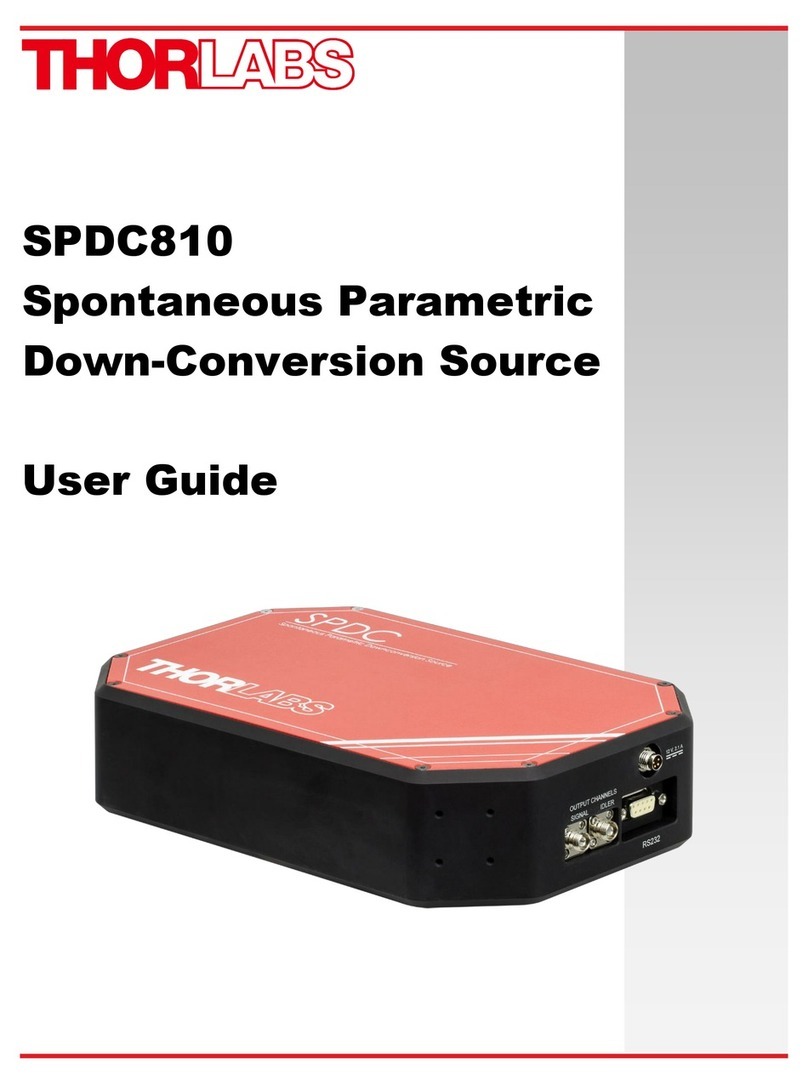
Promise Vess A6120 User manual

Vess A6120
NVR Storage Appliance
Quick Start Guide
Version 1.0
© 2016 PROMISE Technology, Inc. All Rights Reserved.

About this guide
........................................................................................ 1
IntroductIon
.............................................................................................. 1
setup tAsk List
......................................................................................... 2
tAsk 1: unpAck
......................................................................................... 2
Vess A6120
pAcking List
........................................................................... 2
Front pAneL oVerView
................................................................................ 3
reAr pAneL oVerView
.................................................................................. 4
tAsk 2: Mounting Vess A6120
in ArAck
................................................ 5
tAsk 3: instALLing disk driVes
................................................................. 8
driVe cArrier hArdwAre
............................................................................. 8
tAsk 4: MAnAgeMent connection
........................................................... 11
ManageMent Path - on sIte keyboard and MonItor
..................................... 11
MAnAgeMent pAth - network connection
.................................................. 12
tAsk 5: connecting the power
............................................................. 12
Power onVess a6120 systeM
.................................................................. 12
bAck pAneL Leds
.................................................................................... 13
Front pAneL Leds
.................................................................................. 14
tAsk 6: Access operAting systeM gui
................................................ 15
Log in to windows
................................................................................... 16
tAsk 7: creAting LogicAL driVes
........................................................... 17
Logging into webpAM proe
................................................................. 17
choosIng aLanguage
................................................................................ 18
creatIng your LogIcaL drIVes
................................................................... 19
systeM shutdown
................................................................................... 25
Promise Technology
ii
Quick Installation Guide

PcI/PMc add-on hardware
.......................................................................26
AVAiLAbLe pci/pMc hArdwAre coMbinAtions
...........................................27
product registrAtion
............................................................................29
register your Vess A-series
...................................................................31
open Aweb support cAse
.........................................................................33
contactIng technIcaL suPPort
..................................................................35
technIcaL suPPort serVIces
......................................................................35
iii
Vess A6120 NVR Storage Appliance

About this guide
This Quick Start Guide provides an introduction to the hardware components
of the Vess A6120 Storage Server Appliance, as well as instructions for how
to install the device in an equipment rack, and how to connect the power, a
keyboard and monitor used for the initial conguration setup. Then power on
the system, login as administrator and create a RAID drive for storage video
data. When you have completed the instruction in this guide, you need to read
the Product Manual, and other user documentation available from Promise,
for additional instructions on how to connect the system to the surveillance
network, connect to additional network storage if needed, how to install video
management software, how to administer, manage and maintain the system,
as well as how best to scale the system to suit the requirements of your
surveillance and data storage network.
This guide also includes information about:
• Product Registration page 29
• Contacting Technical Support page 35
IntroductIon
The particular installed hardware mix ordered will determine the role of the
Vess A6120 on your network. The Vess A6000 Series server can be equipped
to provide various services, including:
• Intelligent Video Analytic Server for Surveillance
• Management Server for Surveillance
• Recording Server for Surveillance
1
Vess A6120 Storage Server Appliance

setup tAsk List
To setup the Vess A6120 system, perform these hardware and conguration
tasks in order:
• Task 1: Unpack device
• Task 2: Mount Vess A6120 in a standard rack
• Task 3: Remove front bezel and install hard disk drives
• Task 4: Management connections
• Task 5: Connect the power and power on system
• Task 6: Login to Windows
• Task 7: Login to WebPAM PROe
• Task 8: Create Logical Drives
tAsk 1: unpAck
Vess A6120
PAcking List
The Vess A6120 box contains the following items:
• Vess A6120
• Front bezel secure cover
• 1.5m (4.9 ft) Power cord
• Screws for disk drives
(20 pieces for 4 bays)
• Sliding rail assembly for rack mounting
Note
The Product Manual and this Quick Start Guide, in PDF format, are
found on the desktop after booting up and logging in
Promise Technology
2
Quick Installation Guide

The Vess A6120 is shipped with a lockable front secure cover which must be
removed in order to access the hard disk drive carriers. Use the tubular key to
lock or unlock this cover.
The front panel features the power button, various LEDs, USB ports and the
tubular lock. See “Power On Vess A6120 system” on page 12 and
“Front Panel LEDs” on page 14 in this guide for more information.
Front PAneL oVerView
No. Description
14 x 3.5" Hot-Swap HDD Trays (HDD0~HDD3)
22 x USB 2.0 Ports
3 Control Panel Buttons and LEDs
4 VGA Port
HDD0 HDD1 HDD2 HDD3
12 3 4
Front Panel without bezel cover
Front Panel with bezel cover 3
3
Vess A6120 Storage Server Appliance

reAr PAneL oVerView
The rear panel of the Vess A6120 provides a network port for system
administration. This is also where the VGA video port is located, USB 3.0
ports, and the power insert for the power connection.
Other features depend on what PCIe card, or combination of PCIe cards are
installed. Please see the Product Manual for a complete list of the supported
PCIe hardware options.
The types of ports and connections available on the Vess A6120 include:
• Two port 10G BASE-T
• Two port 10G SFP+
• Two port 1G BASE-T
• Four port 1G BASE-T
• SAS HBA (SFF-8644)
• M.2 RAID card
For a complete list of the available port options, please see the Product
Manual. For a brief overview of PCIe and PMC hardware options, see “PCI/
PMC add-on hardware” on page 26.
Vess A6120 rear view
VGA port
1000BASE-T
IPMI port
1000BASE-T
2 port NIC
Power inserts USB ports
four USB 3.0 ports
PCI slots
RS-232
Serial port
Promise Technology
4
Quick Installation Guide

tAsk 2: Mounting Vess A6120
in ARAck
The instructions here apply to the all Vess A6120 Series 1U form factor
models.
The Vess A6120 installs in a 19” equipment rack. Please examine the
illustrations in this section to make sure you are using the correct type of rack.
In order to place the system in the rack, rst attach the ear brackets to the
front of the device. Then install the sliding rail system in the rack. Finally place
the device on the sliding rails and secure it to the rack. Use only the screws
and fasteners included with the shipment of the sliding rail system, or with the
Vess A6120. This procedure is described and illustrated in the sections that
follow below.
Warnings
• Elevated Operating Ambient - If installed in a closed
or multi-unit rack assembly, the operating ambient
temperature of the rack environment may be greater
than room ambient. Therefore, consideration
should be given to installing the equipment in an
environment compatible with the maximum ambient
temperature (Tma) specied by the manufacturer.
• Reduced Air Flow - Installation of the equipment in
a rack should be such that the amount of air ow
required for safe operation of the equipment is not
compromised.
• Mechanical Loading - Mounting of the equipment in
the rack should be such that a hazardous condition
is not achieved due to uneven mechanical loading.
• Circuit Overloading - Consideration should be given
to the connection of the equipment to the supply
circuit and the effect that overloading of the circuits
might have on over current protection and supply
wiring. Appropriate consideration of equipment
nameplate ratings should be used when addressing
this concern.
• Reliable Earthing - Reliable earthing of rack-
mounted equipment should be maintained.
Particular attention should be given to supply
connections other than direct connections to the
branch circuit (e.g. use of power strips).
5
Vess A6120 Storage Server Appliance

Promise Technology
6
Quick Installation Guide
1. For both sliding rail assemblies, release and detach the inner
member from the slide.
2. Attach the inner member of the sliding rail assembly to each side of
the Vess A6120.
Follow these steps to install the mounting rails in an equipment rack.

7
Vess A6120 Storage Server Appliance
3. Fix the outer member of the rail assembly to the rack frame.
4. Carefully insert the Vess A6120 to complete the installation.

tAsk 3: instALLing disk dRiVes
The Vess A6120 system supports:
• SATA hard disks
• 3.5-inch hard disk drives
For a list of supported physical drives, download the latest compatibility list
from the PROMISE support website.
Empty drive carrier side view
Front
Empty drive carrier top view
Front
DriVe cArrier hArDwAre
Promise Technology
8
Quick Installation Guide

Follow these steps to install the hard disks:
1. Press the drive carrier release button. The handle springs open.
2. Grasp the handle and gently pull the empty drive carrier out of the
enclosure.
Cautions
Swing open the drive carrier handle before you
insert the drive carrier into the enclosure.
To avoid hand contact with an electrical hazard,
remove only one drive carrier a time.
Disk carrier release button
Drive carrier front view
9
Vess A6120 Storage Server Appliance

3. Place the physical drive on a table with the bottom side facing up.
4. Position the drive in the carrier over the physical drive so the
mounting holes line up (see below)
Note there are different mounting screw holes for 2.5” drives.
5. Insert the screws through the proper holes in the carrier and into the
drive or adapter.
• Install four screws per drive.
• Snug each screw. Be careful not to over tighten.
6. With the drive carrier handle in open position, gently slide the drive
carrier into the enclosure.
Important
Press the release button to push the drive carrier into position.
Proper drive installation ensures adequate grounding and
minimizes vibration. Always attach the drive to the carrier with
four screws.
`
Bottom of 3.5” HDD
Screw holes for
mounting 2.5”
SSD or HDD
Mounting screws
Mounting screws (3.5” HDD)
Drive carrier handle (front)
Promise Technology
10
Quick Installation Guide

tAsk 4: MAnAgeMent connection
The Vess A6120 can be remotely managed through the IP network. The
physical connection for management is provided by connecting to either
of the two 1000BASE-T ports on the installed NIC. Alternatively you can
attach a monitor to the VGA, and connect a USB keyboard and manage
the initial setup conguration via direct connection to the device, using the
Command Line Interface. This Quick Start Guide describes only the second
option, connecting to the device with a monitor and keyboard. For remote
management through the surveillance and data network, please see the
Product Manual.
ManageMent Path - on site keyboard and Monitor
Use a USB keyboard and a VGA monitor to establish a direct out-of-band
connection to the management software. The VGA and USB ports are located
on the back of the Vess A6120. Connect a VGA monitor to the appropriate
video monitor port, and connect a USB keyboard to any USB port on the rear
panel.
Management via direct attached keyboard and monitor is done with the
command line interface (CLI). Please see the Product Manual for a list of
commands, use and login information.
Vess A6120 rear panel video monitor connecons and USB ports
VGA port
Connect to
VGA monitor
USB ports
Two USB 3.0 ports; connect to keyboard
1000BASE-T
2 port NIC
Use these ports for system management via IP network
11
Vess A6120 Storage Server Appliance

MAnAgeMent PAth - network connection
The Gigabit Ethernet RJ-45 ports on the rear panel for the network connection
used for device administrator. These ports must be physically and logically
located in the IP subnet used by the system administrator.
To establish the management path:
1. Attach one end of an Ethernet cable to the network connector or
standard NIC in the Host PC.
Attach the other end of the Ethernet cable to one of the ports on the standard
network switch on the subnet used for system administration.
2. Attach one end of an Ethernet cable to one of the ports on the same
network switch or subnet used for system administration.
Attach the other end of the Ethernet cable to one of the 1000BASE-T ports on
the back of the Vess A6120 .
If you have multiple Vess A6120 systems, Host PCs or Servers, repeat steps
1 and 2 as required.
3. Follow the instructions for connecting to, and conguring the basic
settings of the Vess A6120.
Please note that you do not need to establish a network connection
for the initial setup. The web-based management interface is
accessible using a keyboard and monitor directly attached to the
device. See the next section for instructions.
tAsk 5: connecting the poweR
Insert one power cable into the power receptacle for the power supply and
connect the PSU to a suitable power source.
Power onVess a6120 systeM
With the power supplies connected, the system can now be powered on.
To power on the Vess A6120 system , press the Power button on the front
panel (see “Front Panel without bezel cover” on page 3 for location of
power button). Observe the LEDs on the front panel (see page 14), and
on the back panel (see page 13), to make certain the boot up proceeds
smoothly and the system is connected to the network.
Promise Technology
12
Quick Installation Guide

BAck PAneL LeDs
LED Description
Link/Activity This is lit YELLOW when a
physical link is established; it blinks
YELLOW when there is activity on
the port.
Port Speed GREEN indicates 1000 Mbps.
YELLOW indicates 100 Mbps
Unlit indicates 10 Mbps (or no link).
Management network port LEDs
Swappable power supplies on rear panel
PSU Status LEDs
GREEN indicates healthy PSU.
AMBER indicates a problem.
Power Supply Units (PSU)
Link/Activity
Port Speed
HDD Power
Drive carrier LEDs
HDD Status/Activity
13
Vess A6120 Storage Server Appliance

Front PAneL LeDs
When boot-up is nished, check the LEDs on the front panel to make sure the
system is functioning properly. See the table below.
LED Description
Power This is lit AMBER to indicate the system is powered on.
Error Status This will be lit RED if there is a critical problem with the
RAID (check RAID Status), or with the enclosure (system
fan, temperature or voltage issue, etc.).
When the system is healthy, it remains unlit.
Network
Link/Activity
One LED for each 1000BASE-T LAN port. These are lit
GREEN to indicate a valid link. A blinking GREEN LED
indicates activity on the port.
RAID Status This is lit GREEN when the RAID status is healthy. It will be
unlit if there is a problem with the RAID.
UID This will be lit BLUE when the system identication feature
is active. Otherwise is remains unlit.
Power
LEDs viewed through windows on front bezel
Error
Status
Network
Link/Act
RAID
Status
Promise Technology
14
Quick Installation Guide

tAsk 6: Access opeRAting systeM gui
To access the installed operating system graphical user interface on the Vess
A6120, insert a USB keyboard into any USB port, and connect a monitor
using the VGA port. See “Management Path - on site keyboard and monitor”
on page 11 for description on how to connect.
Windows desktop quick links
Promise management GUI link
User documentation
15
Vess A6120 Storage Server Appliance

Log in to winDows
For Windows installations, once the system has booted up it will be necessary
to choose various options to complete the OS setup. You will be prompted
to select a default language and other user interface preferences. Follow the
instructions on screen to complete your preferences selection and to establish
a user name and password for the administrator. After completing these nal
tasks, the Windows desktop appears. Notice that there are two quick link
icons, one for the a web browser connection to WebPAM PROe and one link
to a le that contains user documents.
Windows desktop quick links
Promise Technology
16
Quick Installation Guide

tAsk 7: cReAting LogicAL dRiVes
Setting up WebPAM PROe consists of the following actions:
• Logging into WebPAM PROe
• Choosing a Language
• Creating Your Logical Drives
• Logging out of WebPAM PROe
Logging into weBPAM Proe
Double click the WebPAM PROe link icon on the desktop to launch the default
browser and go to the login page.
When the log-in screen appears:
• Type administrator in the User Name eld.
• Type password in the Password eld.
• Click the Login button.
The User Name and Password are case sensitive
After sign-in, the WebPAM PROe opening screen appears. If there are any
uncongured physical drives in the enclosure, an Array Conguration menu
also appears.
Note
Make a Bookmark (Firefox) or set a Favorite (Internet
Explorer) of the Login Screen so you can access it easily next
time.
17
Vess A6120 Storage Server Appliance
Table of contents
Other Promise Network Hardware manuals
