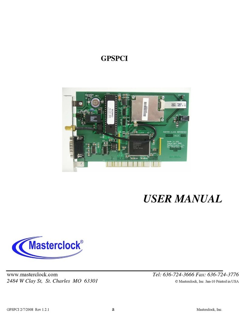
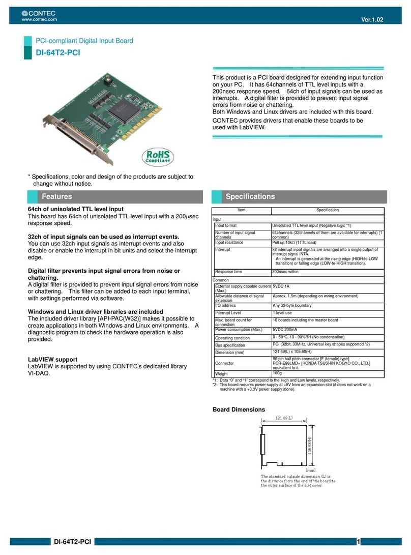
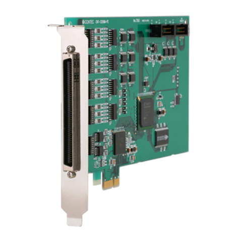
Promise FastTRAK66 User manual

User's Manual
Ultra ATA/66 RAID CardUltra ATA/66 RAID Card
Ultra ATA/66 RAID CardUltra ATA/66 RAID Card
Ultra ATA/66 RAID Card

Copyright
Copyright by PromiseTechnology, Inc. 1999. All rights reserved. No part
of this manual may be reproduced or transmitted in any form without the
expressed written permission of Promise Technology, Inc.
Promise Technology is not liable for any errors contained herein or
incidental or consequential damages in connection with furnishing this
material.
The published material in this manual is subject to change without notice.
Promise reserves the right to make changes in the product design, layout,
and driver revisions without notification to its users.
Trademarks
All trademarks are properties of their respective holders.

RADIOFREQUENCYINTERFERENCESTATEMENT
Each FastTrak66 Ultra ATA/66 RAID card is equipped with an FCC
compliance label and shows an FCC identification number. The full text of
the associated label is:
CAUTION: Changes or modifications to the FastTrak66 not expressly
approved by PROMISE TECHNOLOGY, INC. could void the user’s
authority to operate this equipment.
This equipment has been tested and found to comply with the limits for
a Class B digital device, pursuant to Part 15 of the FCC Rules. These
limits are designed to provide reasonable protection against harmful
interference in a residential installation. This equipment generates, uses
and can radiate radio frequency energy, and, if not installed and used in
accordance with the instruction may cause harmful interference to radio
communications. However, there is no guarantee that interference will
not occur in a particular installation. If this equipment does cause harmful
interference to radio or television reception, which can be determined
by turning the equipment off and on, the user is encouraged to try to
correct the interference by one or more of the following measures:
- Reorient or relocate the receiving antenna.
- Increase the separation between the equipment and receiver.
- Connect the equipment into an outlet on a circuit different from that
to which the receiver is connected.
- Consult Promise Technology, Inc. or an experienced radio/TV
technician for help.
This device complies with Part 5 of the FCC Rules. Operation is
subject to the following conditions: (1) This device may not cause
harmful interference, and (2) this device must accept any interference
received, including interference that may cause undesired operation.
NOTE: Only digital device equipment CERTIFIED CLASS B should
be attached to this equipment and that must have shielded cables.

Table of Contents
Introduction ....................................................................................... 1-1
What is the FastTrak/FastTrak66 RAID Card? ........................................... 1-1
Key Features and Benefits .......................................................................... 1-1
Getting Started ................................................................................... 2-1
Unpacking Your FastTrak66 ....................................................................... 2-1
Quick Installation ........................................................................................ 2-2
Hardware Installation....................................................................... 3-1
Install the FastTrak66 Card ........................................................................ 3-1
Set IDE Drive Jumper Settinngs .................................................................. 3-1
Attaching Drives to Connectors ................................................................. 3-1
Drive Attachment Order by Connector ....................................................... 3-2
Installation Scenarios ................................................................................. 3-2
FastBuildTM Configuration Setup..................................................... 4-1
BIOS Startup Screen ................................................................................... 4-1
FastBuildTM SetupMenu Navigation ........................................................... 4-1
Main Menu ................................................................................................. 4-2
Auto Setup ................................................................................................. 4-3
View Drive Assignments ............................................................................. 4-4
Define Array ............................................................................................... 4-5
Delete Array Menu ..................................................................................... 4-9
Rebuild Array ........................................................................................... 4-10
Controller Configuration ........................................................................... 4-12
FastCheckTM Win 95/98/NT Monitoring Utility ............................ 5-1
Installation .................................................................................................. 5-1
Running FastCheck .................................................................................... 5-2
FastCheck Monitoring Utility Main Screen ................................................ 5-3
Array Window ............................................................................................ 5-3
Array Synchronization ................................................................................ 5-6
Array Rebuild ............................................................................................. 5-7
Rebuild Wizard ............................................................................................ 5-8
Controller Window .................................................................................... 5-11
Options Window ....................................................................................... 5-13
i

Table of Contents
Understanding Disk Array Concepts ............................................. 6-1
Disk Array Adapter .................................................................................... 6-1
Adapter BIOS ............................................................................................. 6-1
FastBuildTM Auto Menu Setup ................................................................... 6-1
Reserved Sector .......................................................................................... 6-1
Disk Array Terms ........................................................................................ 6-2
Supported Disk Array Types ...................................................................... 6-3
Operating System Installation ......................................................... 7-1
DOS ............................................................................................................ 7-1
Microsoft Windows 3.1x ............................................................................. 7-2
Windows 95/98 Driver ................................................................................ 7-2
Windows NT 3.5x & NT 4.0 ........................................................................ 7-3
Installing Driver in Existing Windows NT System ...................................... 7-3
Removing Driver From Windows NT 3.5x ................................................... 7-4
Installing in Existing Windows NT 4.x System ........................................... 7-4
Removing Driver From Windows NT 4.x ..................................................... 7-5
Troubleshooting & Tips ................................................................... 8-1
Troubleshooting ......................................................................................... 8-1
Tips for Audio/Video Editing ...................................................................... 8-4
Appendices
Frequently Asked Questions.......................................................... A-1
Pre-Installation (Speed, Device Types, Capacity, Cabling) ........................ A-1
Installation Issues (NT, I2O Drivers, Capacity, Booting, IRQ Settings) ..... A-4
Post-Installation (Power Up, BIOS , Memory, Caching, Booting) .............. A-5
Contacting Technical Support ......................................................... B-1
Warranty Information ....................................................................... C-1
Limited Warranty .............................................................................................
Disclaimer of Other Warranties ........................................................................
Returning a Product for Repair ...................................................... D-1
ii

Chapter 1
Introduction
Congratulations on choosing Promise Technology's innovative FastTrak66 Ultra
ATA/66 RAID card for IBM PC compatible systems. This card is designed to boost
sustained transfer rates and/or provide fault tolerance for the latest Ultra ATA/66
hard drives, while being backward-compatible with Ultra ATA/33, Enhanced IDE,
and Fast ATA-2 high performance hard disk drives.
What is the FastT rak66 RAID Card?
Promise designed its FastTrak66 card to provide a cost-effective, high performance
RAID card that adds performance and/or reliability to PC desktops and/or servers
using Ultra ATA/66, Ultra ATA/33, or EIDE drives.
FastTrak66 supports striping (RAID 0), mirroring (RAID 1), striping/mirroring (RAID
0+1), or spanning (JBOD) operation , respectively. With striping, identical drives
can read and write data in parallel to increase performance. Mirroring increases read
performance through load balancing and elevator sorting while creating a complete
backup of your files. Striping with mirroring offers both high read/write perfor-
mance and error tolerance. Spanning uses the full capacity of all attached drives
without requiring identical drive size, but offers no other RAID functionality.
A FastTrak66 striped array can double the sustained data transfer rate of Ultra
ATA/66 drives. FastTrak66 fully supports Ultra ATA/66 specification of up to 66
MB/sec per drive, depending on individual drive specifications.
FastTrak66 also offers fault tolerant, data redundancy for entry-level network file
servers or simply for desktop PC users wanting to continually protect valuable data
on their PC. FastTrak66 offers RAID 1 mirroring (for two drives) and RAID 0+1
mirroring and striping (for four drives) to protect data. Should a drive that is part of
a mirrored array fail, FastTrak66 uses the mirrored drive (which contains identical
data) to assume all data handling. When a new replacement drive is later installed,
FastTrak66 rebuilds data to the new drive from the mirrored drive to restore fault
tolerance.
FastTrak66's bootable BIOS supports individual drives larger than 8.4GB. With
FAT32 and NTFS partitioning, the array can be addressed as one large single vol-
ume.
Key Features and Benefits
The following information offers an overview of the major features of your new
Promise FastTrak. It is divided into two areas: Advanced Hardware Design, and
Compatibility.
1-1

Introduction
Features Benefits
Supports data striping (RAID 0),
mirroring (RAID 1), and striping/
mirroring combination (RAID 0+1)
Supports Ultra DMA 4/3/2/1/0, DMA 2/
1/0
PCI Plug-n-Play, PCI Interrupt sharing and
coexists with mainboard IDE controllers
Supports concurrent dual IDE controller
operation
Supports IDE bus master operation
Utilizes FastBuildTM automenu from the
FastTrak66 onboard BIOS
Displays status and error checking messages
during bootup
Employs the latest Promise PCI Ultra
ATA/66 ASIC technology.
Mirroring supports automatic background
rebuilds
Provides dramatic increase in drive
performance and/or fault tolerant options.
Offers performance customization and data
rebuilds from the BIOS menu.
Burst data transfer rates up to 66MB/sec
from Ultra ATA/66 drives to boost overall
system performance.
Easy to install; support four IDE drives on
the FastTrak66 while still supporting 4 IDE
devices on the mainboard IDE controllers.
Drive workload is distributed in parallel
between members of the array.
Allows multiasking during disk transfers
which increase CPU efficiency. The CPU
is free to process tasks during IDE data
transfers through the PCI Bus to/from
system memory.
Offers pre-set application specific settings
which can be optimized for Desktop, Server,
or A/V Editing. Has "Auto Setup" option for
quick and easy array builds.
Notifies user of possible errors and allows
for recovery of mirrored drive arrays
directly from FastBuildTM .
Fully supports Ultra ATA/66
specifications with 66MB/sec timing and
CRC error-checking at high drive speeds.
Fault tolerance can be restored
automatically without rebooting
Advanced Hardware Design
1-2

Introduction
Features Benefits
Complies with PCI v2.1 Local Bus standard
Compliant with PCI IDE Bus Master
standard. PCI IDE Bus Master support for
Windows95, Windows NT 3.5x, 4.0
Tested compatiblity to coexist with
Mainboards that have integrated IDE
controllers
Compatible with Ultra ATA/66, Ultra
ATA/33, EIDE and Fast ATA-2 drives
supporting multi-word DMA
Features LBA and Extended Interrupt13
drive translation in controller onboard BIOS
Provides highest level of hardware
compatibility.
Provides 32-bit I/O, IDE Bus Master, and
Ultra ATA performance for optimal system
performance.
Improves system performance of new and
existing installations including mainboards
with Intel chipsets.
Works with newest and current IDE drive
specifications. Promise engineers
experienced with IDE devices perform
verification testing with major drive
manufacturers and development partners.
Breaks capacity barriers for support of drives
greater than 8.4GB in capacity. Offers
flexible storage options for space demanding
applications.
Compatibility
1-3

Introduction
This Page Intentionally Left Blank

Chapter 2
Getting Started
This section is designed to get you started for installation of your FastTrak66.
Unpacking Your FastT rak66
When you receive the FastTrak66, the package should contain the items listed
below:
w FastTrak66 Ultra ATA/66 RAID Card
w FastTrak66 User’s Manual
w Registration Card
w FastTrak66 Driver floppy diskette
w Two Internal 80-wire/40-pin Ultra ATA/66 hard drive cables (18” length)
CAUTIONINHANDLINGAND INSTALLING!
Before installing the adapter into an existing system, backup any necessary data.
Failure to follow this accepted PC practice could result in data loss.
Power off the system. Be careful when handling the controller. The FastTrak, like
any valuable part of your computer system, is susceptible to static electricity. Be
sure you are well grounded for the installation.
If ANY of the contents are missing or appear to be damaged, please contact your
dealer or distributor immediately.
Board Layout
IDE1IDE2
IDE1
IDE2
LED
First IDE channel
Second IDE channel
4-pin LED connector:
Pin1PWR, Pin2 GND,
Pin3 GND, Pin4 PWR
Connectors
21-1-1

Quick Installation
Quick Installation
This section is designed to get you started for quick installation of your FastTrak66.
Use drives that are preferably the same model and capacity. NOTE: If using older
IDE drives (less than 300MBs), check with the manufacturer if it supports Multi-
DMA transfers.
[ 1 ] Install FastTrak66 and Drives
Power off the system and ground yourself by touching exposed metal of the PC
chassis.
Connect 18” 80-wire/40-pin cables to the FastTrak66 and hard disk drives. Make
sure the blue plastic connector is used for
the FastTrak66 slots. Attach the darker con-
nectors to the drives. Note that the colored
cable edge indicates Pin 1.
Jumper and install the drives with proper
mas-
ter/slave jumper settings recommended by
the drive manufacturer. When 2 drives are
attached, configure each drive as a master
(with no slave attached) and each drive on
a separate channel. Check drive instruc-
tions for details on Master & Slave settings.
Attach the case LED 2-pin or 4-pin cable
to the FastTrak66 4-pin
power/ground connector labeled LED. Be sure to align pin 1 of the
LED cable to pin 1 of the connector.
Insert and secure the FastTrak66 into an open PCI slot. Re-check
cabling for proper connection.
LED
1
----
M
M
M & S
Total Drives IDE1 IDE 2
One
Two
Three
Four
M
M
M & S
M & S
FastTrak66 Drive Setup
2-2

Quick Installation
[ 2 ] Set Mainboard CMOS Setup
No changes are necessary in the Mainboard CMOS Setup for resources or drive
types. Since FastTrak66 is a PCI Plug-n-Play (PnP) device, the Interrupt and Port
address resources are automatically assigned by the Mainboard’s PCI PnP BIOS.
For the FastTrak66 to be the bootable IDE controller, confirm in the mainboard’s
Standard CMOS Setup that the drive types (for hard disk drives) are set for “Not
Installed” or “None”. Or use “Boot to SCSI” option, if this setting is available in the
motherboard’s BIOS. No changes are needed for CD-ROM drives that are attached
to the mainboard IDE controller.
[ 3 ] Configuring FastBuild BIOS Setup
During bootup, the FastBuild BIOS appears on the screen and displays BIOS ver-
sion information.
1) Press <Ctrl-F> to enter the FastBuild utility.
2) Press <1> for Auto Setup.
• Under the “Optimize Array for” option, choose the “Performance”, “Fault
Tolerance”, or “Capacity”.
• For the “Typical Application Usage” option, select the appropriate setting
with the <Space> key.
See Chapter 4 for details on FastBuild Configuration Setup.
3) Press <Ctrl-Y> to save and “Yes” to save and reboot the system. NOTE: the
disk array will be seen as one physical drive by the operating system.
Drives types are identified as
“Not Installed” or “Boot to
SCSI” (if available)
System Date Jan 1 1999
System Time 09:0 0: 00
Floppy Options
Primary IDE Master
Primary IDE Slave
Secondary IDE Master
Secondary IDE Slave
Language
Boot Options
Video MOde
Mouse
Base Memory
Extended Memory
BIOS Version
Press Enter
Not Installed
Not Installed
Not Installed
Not Installed
English (US)
Press Enter
EGA / VGA
Installed
640KB
31744KB
1.00.00.00
Main Advanced Security Exit
2-3

Quick Installation
[ 4 ] Starting the Operating System
See the steps below for a new operating system installation. For other supported
operating systems, see Chapter 7 for instructions.
1) Boot to Disk 1 of the DOS installation diskettes or manually partition and
format new drives with standard DOS FDISK and FORMAT utilities.
2) Install DOS, Windows, and/or Windows95/98 using the “Setup.exe” utility
found on the Microsoft installation diskettes.
Driver Installation
For DOS and Windows 3.1x: No drivers need to be installed. The FastTrak66 BIOS
will provide enhanced operation.
Windows95/98 setup will show a “New Hardware Found” dialog box. Under ver-
sions 4.00.950 and 4.00.950 an “Unknown PCI Device” will be detected. Under
versions 4.00.950 B “PCI RAID Controller” will be displayed.
NOTE: Obtain the Windows95/98 version number as follows: 1) Under the My
Computer icon, click Control Panel; 2) click the System icon. Note the version
number that appears here.
1) In the dialog box, choose “Driver from disk provided by hardware manufac-
turer” button. In the a: drive, insert the FastTrak66 utility diskette and type in
“A:\” where prompted for the directory.
2) Select “Promise Technology, Inc. PCI FastTrak66 Driver” and click on Next.
The FastTrak66 driver is now copied onto the system and entered into the
Windows95/98 driver database.
3) When the "System Settings Change" dialog box appears, remove the floppy
diskette and click on “Yes” to restart the system. Windows95/98 will then
restart for the driver installation to take effect.
Confirming Windows95/98 Installation
From Windows95/98, open the Control Panel from My Computer followed by the
System icon. Choose the “Device Manager” tab and click the “+” in front of the
“SCSI Controllers” hardware type. The driver “Promise Technology, Inc. PCI Fast-
Trak66 Driver” driver should be installed.
2-4

Chapter 3
Hardware Installation
Install the FastT rak66 Card
Insert and secure the FastTrak66 card into a PCI Bus Master slot. There are no
hardware configurable jumpers or settings to change due to the adapter’s Plug-n-
play (PnP) features.
The FastTrak66 system resources including port address, interrupt, and BIOS
address are automatically determined by the system PnP BIOS.
To customize IRQ settings, enter the Mainboard BIOS’s Advanced PCI setup and
follow the manufacturer’s procedures. When the system is limited by IRQ resources,
the FastTrak66 card can be set for the same IRQ as other PCI cards that support PCI
interrupt sharing.
Set IDE Drive Jumper Settings
Drives must be Ultra ATA/66, Ultra ATA/33, EIDE and/or Fast ATA-2 compatible to
operate with the FastTrak66 RAID Adapter. For optimal performance, install all
identical drives of the same model and capacity. The drives’matched performance
allows the array to function better as a single drive.
Refer to the drive manufacturer documentation for proper Master / Slave settings.
Note that sometimes the Master drive with no slave attached is called “Single.” The
master slave setting differentiates two drives chained on the same connector.
Attaching Drives to Connectors
Attach drives with the supplied 18” 80-wire/40-pin Ultra ATA/66 cables. Only these
cables will support data transfers up to 66MB/sec and must be used with Ultra
ATA/66 drives. Use all available connectors before chaining a slave drive. This is
recommended for better performance since data can be processed in parallel.
For maximum IDE Fault tolerance, each mirrored pair should be installed on separate
IDE connectors. Drives Attachment Order By Connector
3-1

Hardware Installation
Drives Attachment Order By Connector
The following table shows the order in which drives should be connected to the
FastTrak66 card.
Installation Scenarios
Examine the following installation scenarios which may apply to your system.
Then proceed to Chapter 4 which covers operation of the card’s BIOS utility and
array creation.
FastTrak66 coexisting with onboardATAPI CD-ROM
Do NOT attach ATAPI devices to FastTrak66. FastTrak66 is for hard drives only.
ATAPI IDE CD-ROM drives or other
devices can be installed on
Mainboard or add-on IDE controllers.
No configuration is necessary on the
mainboard BIOS setup.
Total Drives
One
Two
Three
Four
IDE 1
M
M
M & S
M & S
M - Master, S - Slave
IDE 2
—
M
M
M & S
3-2

Hardware Installation
FastTrak66 coexisting with
hard drives on onboard IDE
controller
The FastTrak66 can coexist with
onboard or add-on IDE controller(s)
and hard drives installed.
If the motherboard’s CMOS has a
“boot to SCSI” option, it is possible to
boot from the FastTrak66 and still rec-
ognize the onboard non-bootable
drives.
If the motherboard CMOS does not al-
low booting to SCSI, the boot drive
must be attached on the onboard IDE
controller
FastTrak66 Coexists with SCSI controller
The FastTrak66 is bootable with a SCSI
controller in the system. The adapter
with the lower BIOS address will be
bootable. If it is necessary to change the
boot sequence, swap the FastTrak66
PCI slot position with that of the SCSI
card’s PCI slot.
3-3

Hardware Installation
This Page Intentionally Left Blank

FastBuild TM Configuration Setup
The FastBuildTM setup gives menu choices to create and manage disk arrays on the
Promise FastTrak66 adapter.
BIOS Startup Screen
During the system startup, the Promise BIOS screen will appear as shown above.This
displays the adapter BIOS version and array status. The array status consists of
three possible conditions: Functional, Critical, Offline.
Functional - The array is operational.
Critical - A mirrored array contains a drive that has failed or disconnected. The
remaining drive member in the array is functional. However, the array has tempo-
rarily lost its ability to provide fault tolerance. The user should identify the failed
drive though the FastBuildTM Setup menu utility, and then replace the problem drive.
Offline - A mirrored array has 2+ drives or a striped array has 1+ drives that have
failed or have been disconnected. When the array condition is “offline,” the user
must replace the failed drive(s), then restore data from a backup source.
FastBuild TM Setup Menu Navigation
When using the menus, these are some the basic navigation tips: Arrow keys
highlights through choices; [Space] bar key allows to cycle through options;
[Enter] key selects an option; [ESC] key is used to abort or exit the current menu.
Chapter 4
FastTrak (tm) / FastTrak66 (tm) BIOS Version 1.xx (Build xxxx)
(c) 1995-99 Promise Technology, Inc. All Rights Reserved.
ID MODE SIZE TRACK-MAPPING STATUS
1 * 2+0 Stripe 13044M 611/128/32 Functional
2 1x2 Mirror 6522M 620/32/63 Functional
Press <Ctrl-F> to enter FastBuild (tm) Utility....
4-1

FastBuildTM Configuration Setup
Main Menu
This is the first option screen when entering the FastBuildTM Setup.
To create a new array, follow the steps under the Auto Setup <1> selection or
Define Array <3> selection.
To repair an array, use the <5> Rebuild Array option.
FastBuild (tm) Utility 1.xx (c) 1995-99 Promise Technology, Inc.
[ Main Menu ]
Auto Setup .............................................................. [ 1 ]
View Drive Assignments ....................................... [ 2 ]
Define Array .......................................................... [ 3 ]
Delete Array .......................................................... [ 4 ]
Rebuild Array ......................................................... [ 5 ]
Controller Configuration ...................................... [ 6 ]
[ Keys Available ]
Press 1...6 to Select Option [ESC] Exit
4-2

FastBuildTM Configuration Setup
Auto Setup <1>
The <1> Auto Setup selection can intuitively help create your disk array. It will
assign all available drives appropriate for the disk array you are creating.
FastBuild (tm) Utility 1.xx (c) 1995-99 Promise Technology, Inc.
[ Auto Setup Options Menu ]
Optimize Array for: Performance
Typical Application usage: General
[ Auto Setup Configuration ]
Mode ...................................................... Stripe
Spare Drive Count ........................................ 1
Drive used in Array ...................................... 2
Array Disk Capacity ........................... 13044
[ Keys Available ]
[] Up [] Down [, , Space] Change Option [ESC] Exit [Ctrl-Y] Save
The “Optimize Array for:” setting has three choices - Performance (Striping), Fault
Tolerance (Mirroring), and Capacity (Spanning).
Striping (Performance)
Supports the maximum performance where the capacity equals the number of drives
times the capacity of the smallest drive in the disk array. Change the Stripe Block
sectors that best optimizes system applications. Using a Stripe Block size of 8 KB is
normally recommended for business applications and 64KB for server and Audio/
Video editing applications.
Capacity (Spanning)
Achieves the maximum amount of capacity by adding the sum of all the drives. The
Stripe Block option does not apply.
Mirr oring (Fault Tolerance)
Allows creation of fault tolerant arrays for data security. Also provides a feature to
add fault tolerance to one drive with existing data. The Stripe Block option does not
apply.
Typical Application usage
Allows the user to choose the type of software to optimized for speed enhance-
ment. The recommended stripe will then appear in the [ Auto Setup Configuration ].
4-3
Other manuals for FastTRAK66
1
Table of contents
Other Promise PCI Card manuals
