PROMIX SHERIFF-1 premium User manual
30.08.2017
2
3
b
4
b
5
7
6
1
4а
8
3а
SHERIFF-1 premium
ELECTROMECHANICAL LOCK
OPERATING MANUAL
TU 3428 – 003 – 80210527 – 14
PATENT OF INVENTION №238261
1. APPLICATION
Electromechanical lock "Sheriff-1 premium" is designed for locking hinged doors, opening inward and outward, with a possibility of
remote opening them with the controllers of access control systems, audio and video door phones, code access panels. The lock
design and the method of installation allowyou to place the lock indoor and outdoor of protected premises.
2. OPERATING CONDITIONS
Climatic operating conditions:
- ambient air temperature: from -40 to +50°С;
- relative air humidity not more than 95% at 35°Сand with lower temperatures without condensation and frost formation;
- installing indoors in any type of doors;
- resistance to the environmental exposure complies with GOST 15150-69:UHL2.
3. TECHNICAL SPECIFICATIONS
The lock "Sheriff-1 premium" is produced in the normally open type (or fail-safe), the lock remains open when the voltage
supply is off and is closed when the voltage supply is on. The lock has two integrated sensors: of the door position and of the lock
status.
Integrated sensor of the door position consists of the reed switch placed on the lock case and the magnet placed on the
movable bush of the lock and moved by the deadbolt. The reed switch contacts are open when the door is open (the deadbolt is out
of the lock) and are closed when the door is closed (the deadbolt abuts to the lock).
Integrated sensor of the lock status consists of the reed switch fixed to the electromagnet coil of the lock. The reed switch
contacts are open when the voltage supply is off, and are closed when the current flows on the coil.
Thus, if insert consistently both sensors in the circuit, then the circuit will be closed only when the deadbolt is in the lock (the
door is closed) and the lock draws current (the status is closed).
* Note: 1. The lock in this delivery set (see Para. 4) is designed to be mounted on the door with the door stop width more than 25,5mm
and the door leaf thickness 25-45mm. To mount the lock on the door with other dimensions needed to use the Additional
fixation set (see the Operating Manual).
2. The length of the bolt М8х35 for
deadbolt
fixing (without head) should be less than the thickness of the door on 3-7mm
(shorten the bolt if needed).
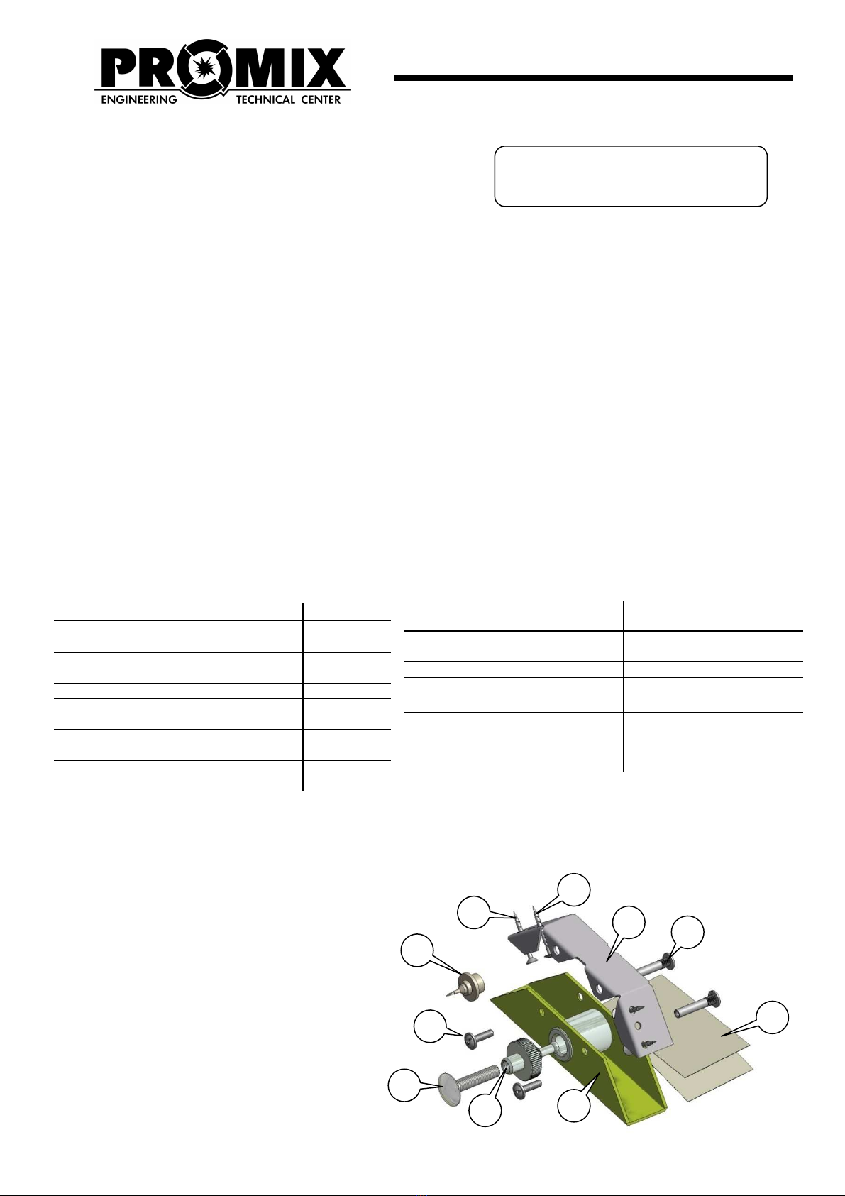
4. DELIVERY SET
1 – Lock 1 pc.
2 – Bracket 1 pc.
3а– Binder bolt M4 for lock fixing 2 pcs.
3б– Screw М4 2 pcs.
4а– Screw 4х30 for bracket fixing 2 pcs.
4б– Countersunk screw 4х30 for bracket
fixing 2 pcs.
5 – Deadbolt assembly 1 pc.
6 – Bolt М8х35 for deadbolt fixing 1 pc.
7 – Template for brackets fixing 1 pc.
8 – Marking tool 1 pc.
9 – Operating manual 1 pc.
10 – Additional fixation set 1 pc.
Check completeness of the delivery set while purchasing.
Subsequently, the company-manufacturer does not accept any claims over completeness of the delivery set.
The maximum current of the reed
switches, A, not more than 0.5
The
maximum
voltage
of
the
reed
switches, V, not more than
36
Product type
normally open
Door leaf thickness, mm
25-70*
Possible adjustments
of the locking bolt length;
automatic deadbolt
alignment in the lock
opening
Holding force, kg, no less than 400
DC voltage supply, V
10 - 15
Current consumption
(12
V
),
m
А
,
not
more than
105
L
ock
weight
,
kg
,
not more than
0.3
Dimensions (WхHхL), mm
34х30х130
Four wire cable and power cable
length, m
0.3
Reliability of operation cycles, not
less than
400, 000
Color:
□
white,
□
silver,
□
brown
Production date:
30.08.2017
5. INSTALLATION AND WIRING
The lock should be mounted in the place protected from the direct
It is recommended to install the lock in
conjunction
its service life.
The lock design and the method of
installation
ATENTION!!! 1) When the door
is closed
2) The lock does not operate, when
the
the door - for instance, the door
handle
When the lock is correctly set,
the necessary
open lock during the power supply
may not closed
5.1 INSTALLATION OF THE LOCK
ATENTION!!! (The possibility to use
this
outdoor) is determined by the installer
company
the level of premise accountability, assignment of access restriction
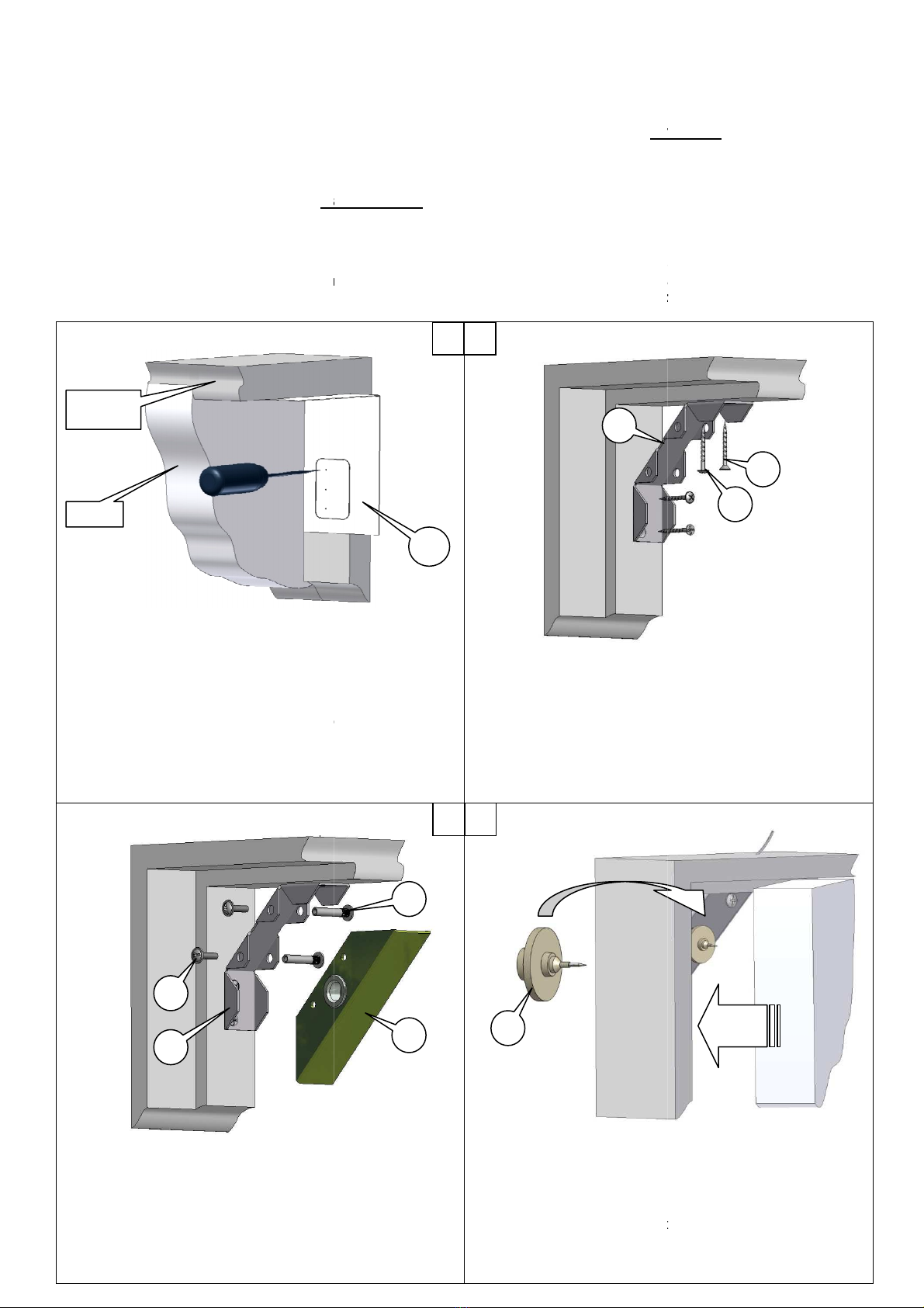
1. Close tightly the door.
2. Place the template 7 above the door
handle
of the door frame. Press down firmly the
marked
template to the door leaf.
3. Puncture th
e template with an awl to mark
holes in the door frame.
For easy mounting of the lock
BE VERY PRECIS
E WHILE MARKING
4. Drill the marked centers of the holes in
the
2mm-diameter-holes for bracket fixing,
5mm-diameter-hole for power cable.
6. Pass the power cable and the four-wire
cable
through the prepared hole; mount the
lock
Rotate binder bolts 3аaround their
axis achieving their easy
insertion in holes and fix them with screws
DO NOT DAMAGE CABLES
WHILE INSTALLING BIN
BOLTS!
DOOR
DOOR
FRAME
2
3
b
2
The lock should be mounted in the place protected from the direct
moisture ingress.
conjunction
with a door closer – it decreases the
impact
installation
allow you to
place the lock indoor and outdoor of protected premises.
is closed
, the deadbolt should be inserted in the lock
to the stop
the
door is in a "tension" state, i.e.
there is an external effort applied for opening
handle
is pulled.
the necessary
clearance (gap) of the door is
2.5-3
mm
.
may not closed
(see Para. 6)!
this
lock to restrict access to premises and the place
of
company
based on the characteristics of the design
and
the level of premise accountability, assignment of access restriction
and other factors (security,
handle
in the top corner
marked
edge of the
e template with an awl to mark
the centers of the
For easy mounting of the lock
E WHILE MARKING
!
the
door frame
5. Fix the bracket 2 with 2 pan
head
countersunk screws 4b.
cable
of the lock
lock
1in the bracket 2.
axis achieving their easy
insertion in holes and fix them with screws
3b.
WHILE INSTALLING BIN
DER
7.Insert the marking tool 8in
the lock
8.Close the door and
press it with an effort
9.
On the door remains the mark, where it is necessary to drill
the through hole 8mm in diameter.
pronounced if
previously to stick on the door the piece of
adhesive tape, duct tape, etc.
7
1
2
1
2
3
4
8
3
a
impact
load on the lock and increases
place the lock indoor and outdoor of protected premises.
to the stop
.
there is an external effort applied for opening
.
If the gap is less, the normally
of
mounting the lock (indoor or
and
the method of installation,
and other factors (security,
CCTV).
head
screws 4аand 2
the lock
1opening.
press it with an effort
.
On the door remains the mark, where it is necessary to drill
the through hole 8mm in diameter.
The mark will be more
previously to stick on the door the piece of
adhesive tape, duct tape, etc.
4
a
Press the
door with
an effort
4
b
30.08.2017
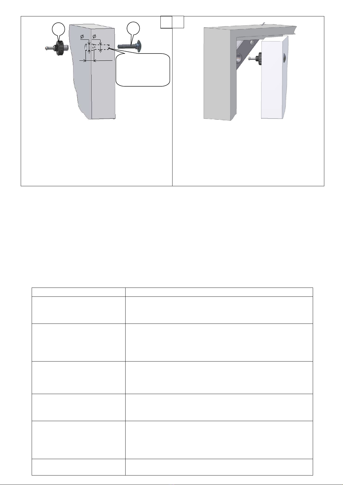
10. Drill the hole in the door where the
deadbolt
10mm in diameter to a depth not less than
11. Insert the bolt 6 in the outside of the
door
hitting it with a hammer.
12. Insert the deadbolt 5in the other side
of
manually tighten it to block. To provide
one may insert in the side of the
deadbolt
rod, a nail, a drill, an awl, etc. (
not included in delivery
While installing the lock and the deadbolt, it is necessary to comply with their axial alignment within the permissible clear
of the deadbolt.
5.2 WIRING ORDER
The lock operates when applying and
interrup
switch (button). Controller installation is
done accord
Attention:
power of the lock is supplied by the voltage from 10 to 15 V of
When the power supply is on the lock is closed, when it is off the lock is open.
The wire assignment:
Red (black with red stripe) –
positive pole of the power supply;
Black –
negative pole of the power supply;
(The reverse polarity voltage supply
does
White, Green – sensor output of
the lock status
Brown, Yellow – sensor output of
the door position
Provide reliable electrical contact. I
solate the connection points to
6. POSSIBLE FAILURES,
INSTALLATION PROBLEM
Failures
and problems
Enlarged clearance
of
the
deadbolt
(more than 2.5mm) when the lock is
closed
The deadbolt does not hold the lock
(the door does not close)
The large gap is between the door
and the door frame during closing the
door (the deadbolt abuts to the lock)
When the status is
"
open
"
, but
the
door does not open. To open the
door needed to press it tighter to the
door frame
During
operation
the
door
is
sagging
(automatic centering of the deadbolt
lacked), as a result the deadbolt
does not reach into the lock opening,
or when it reaches the lock, the
deadbolt clings
The deadbolt does not reach the end
of the lock opening ("balls are stuck")
5
min 16
10 8
Necessarily
of the hole to the door
3
deadbolt
5is fixing,
10mm in diameter to a depth not less than
14mm.
door
and press on it,
of
the door, and
easy tightening
deadbolt
opening a metal
not included in delivery
).
13.
If it is necessary, arrange the length of the
14.
The lock installation is done
While installing the lock and the deadbolt, it is necessary to comply with their axial alignment within the permissible clear
interrup
ting the power supply, and for it
is usually used a controller (contro
done accord
ing to the technical data sheet.
power of the lock is supplied by the voltage from 10 to 15 V of
the direct current.
When the power supply is on the lock is closed, when it is off the lock is open.
positive pole of the power supply;
negative pole of the power supply;
does
not provide operability of the lock, but does not
damage
the lock status
;
the door position
.
solate the connection points to
avoid short-circuiting.
INSTALLATION PROBLEM
S AND TROUBLESHOOT
Troubleshoot
Reduce the length of the locking bolt
. For this purpose
one hand, screw the locking bolt
to the nut with the other hand (or combination
pliers).
Set the lock in the "closed" status (turn on the vo
ltage
polarity and make sure that the power supply corresponds with the required
one.
Fix the knurled nut with one hand, unscrew the
locking bolt
the other hand (or combination pliers).
Fix the knurled nut with one hand, screw the
locking bolt
other hand (or combination pliers).
•Eliminate the causes
of loose fit of the door to the door frame.
•Use the door closer.
•Increase the length of the deadbolt.
Re-establish the door position. If it is impossible,
remove the fastener of
deadbolt from the door. Drill
out a hole in the door with a larger diameter.
Mount the deadbolt
on the door, providing alignment with the lock opening.
Turn off the power supply of the lock. Insert tightly
the steel rod
drill bit, etc.) with diameter 3-
5mm in the lock opening and pull it out.
6
5
6
Necessarily
provide
the
perpendicularity
of the hole to the door
surface!!!
If it is necessary, arrange the length of the
locking bolt.
The lock installation is done
.
While installing the lock and the deadbolt, it is necessary to comply with their axial alignment within the permissible clear
ance
is usually used a controller (contro
l board) or a
the direct current.
damage
it).
. For this purpose
, fix the knurled nut with
to the nut with the other hand (or combination
ltage
supply). Check the
polarity and make sure that the power supply corresponds with the required
locking bolt
from the nut with
locking bolt
to the nut with the
of loose fit of the door to the door frame.
remove the fastener of
the
out a hole in the door with a larger diameter.
on the door, providing alignment with the lock opening.
the steel rod
(screwdriver,
5mm in the lock opening and pull it out.

30.08.2017
4
7. MAINTENANCE
Maintenance of a lock is performed at least once per two months and includes:
- Examination of the lock to check fixation reliability. If it is necessary, tighten up fixing elements of the lock and the deadbolt.
- Check the length of the locking bolt. In case if the locking bolt abuts to the lock, and this is causing a loose fit of the door to
the door frame, or when the door is closed and the lock does not hold the deadbolt - it is necessary to adjust the length of the
locking bolt (see para.6 of the Operating Manual).
The lock does not need lubrication.
8. MANUFACTURER'S WARRANTY
Engineering & Technical Center PROMIX, LLC guarantees the conformity of the electromechanical lock "Sheriff-1 premium" to
the requirements of applicable TU standards under the regulations of operation and installation established in this operating
manual. The warranty period is 18 months commencing from the date of acceptance by Quality Control Department.
Within the warranty period, Engineering & Technical Center PROMIX, LLC undertakes to repair the defective product free of
charge. The shipping cost to the place of repair and back shall be borne by the Buyer.
The warranty shall not cover defects or damages, resulting from:
- improper maintenance by the Buyer;
- using the lock in conditions that do not conform to the operating requirements;
- mechanical damages or disassembly of the lock by the Buyer;
- violation of transportation and storage regulations.
PACKING AND ACCEPTANCE CERTIFICATE
Electromechanical lock "Sheriff-1 premium" with the specified date of manufacture is made and accepted in accordance with TU 3428–
003–80210527–14, obligatory requirements of state standards and applicable technical documents, found fit for service and packed
by Engineering & Technical Center PROMIX, LLC.
QCD seal
Engineering & Technical Center PROMIX, LLC
Russia, 214030, Smolensk city, Krasninskoye Hwy, 35
Tel. (4812) 619-330
www.itc-promix.ru RUSS RU.ММ07.Н00002
PATENT OF INVENTION №238261
Please send us all your comments and suggestions concerning our products via e-mail: [email protected].
Thank you in advance!
30.08.2017
5
SHERIFF-1 premium
ELECTROMECHANICAL LOCK
INSTALLATION MANUAL
ADDITIONAL FIXATION SET
1. APPLICATION
The additional fixation set is designed for mounting Electromechanical lock "Sheriff-1 premium" on the metal, plastic, wood and
other doors with the door stop width from 0 to 25.5mm and the thickness of the door leaf 45-70mm.
2. DELIVERY SET
1. Left angular bracket with hole pattern 1 pc.
2. Right angular bracket with hole pattern 1 pc.
3. Bolt М8х35 for deadbolt fixing 1 pc.
4. Screw М4х8 4 pcs.
5. Nut М4 4 pcs.
6. Locking washer for М4 4 pcs.
7. Installation manual 1 pc.
3. INSTALLATION OF THE LOCK
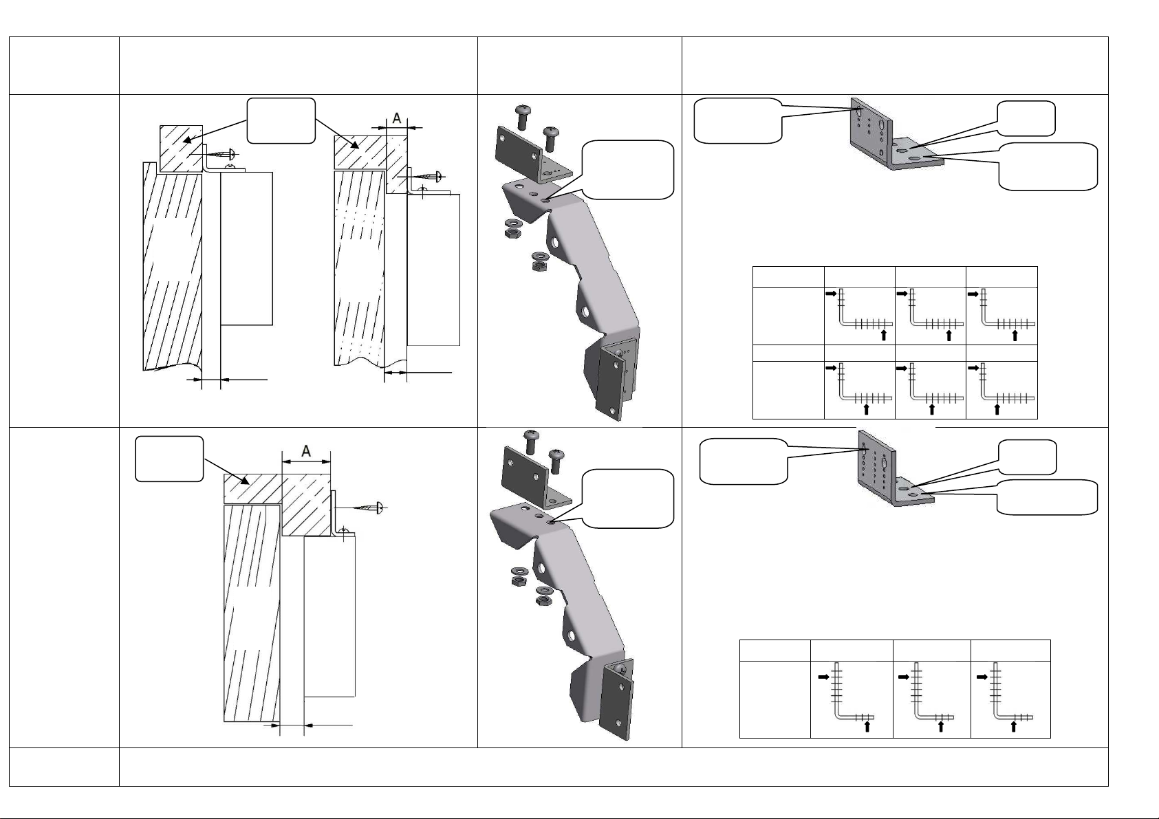
Mounting of the lock depends on the door stop width A (see next page). Drill in specified location (see Table 1, 2) of the
angular bracket 5 holes in diameter 4.2...4.7mm: for fixing to the lock bracket (2 pc.), for power cable (1 pc.), for fixing to the door
frame (2 pcs.). Fix with screws angular brackets and the lock bracket. Fasten the brackets to the lock. Fix the lock to the door
frame. Plug the lock, mark and mount the deadbolt to the door in accordance with the Operating Manual.
In all versions of lock mounting it is necessary, that the distance between the door and the lock case will be from 10 to 13.5mm. The
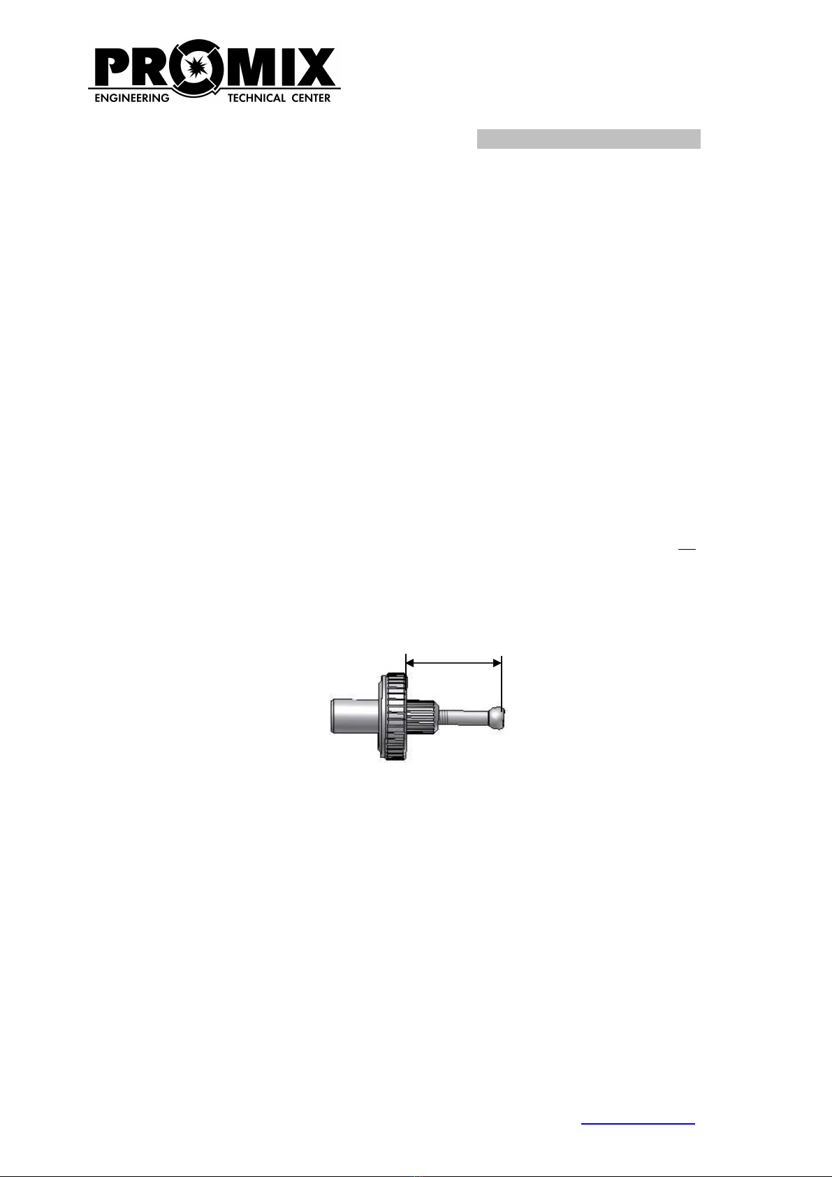
length of the locking bolt, established for the distance from the door to the lock case - 10mm, is 26.5 mm. When the distance is more,
adjust the length by unscrewing the locking bolt. Herewith the length of the locking bolt should not be more than 31mm (see Fig. 1)!
The length of the bolt М8х60 for the deadbolt fixing (without head) should be less than the thickness of the door on 3-7mm
(shorten the bolt if needed).
Fig. 1. The length of the locking bolt
Engineering & Technical Center PROMIX, LLC
Russia , 214030, Smolensk city, Krasninskoye Hwy, 35
Tel. (4812) 619-330
www.itc-promix.ru
Please send us all your comments and suggestions concerning our products via e-mail: [email protected].
Thank you in advance!
26.5
÷
31
6
Door stop
width А(see
Fig.) Installation option Assembly order Explanations
0…17mm
Depending on the door stop width A drill five holes in
diameter 4.2...4.7mm at specified locations of the angular
bracket (see Table 1). Table 1
А, мм 0…2.5 2.5…5.0 5.0…7.5
Holes
drilling
location
А, мм 7.5…10 10…12.5 12.5…17.0
Holes
drilling
location
17…25.5mm
Depending on the door stop width A drill five holes in
diameter 4.2...4.7mm at specified locations of the angular
bracket (see Table 2).
Swap and turn over the lock brackets during the
installation. Table 2
А, мм 17.0…20.5 20.5…23.0 23.0…25.5
Holes
drilling
location
25.5mm and
more The lock fixing carried out in accordance with the Operating Manual.
LOCK
Door
frame
LOCK
LOCK
Door
frame
DOOR
DOOR
DOOR
Locations of
fixing to the
door frame
Locations of
fixing to the lock
bracket
Cable
location
Locations of
fixing to the
door frame
Cable
location
Locations of fixing
to the lock bracket
Please note the
holes locations!
Please note the
holes locations!
10
mm
10
mm
10
mm
Table of contents


