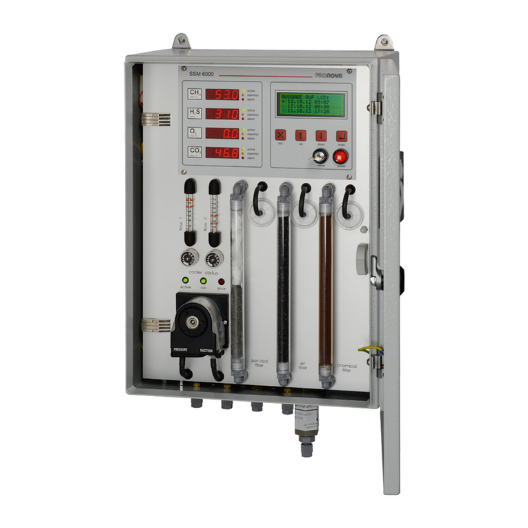
PRONOVA FOS/TAC 2000 User manual

User Manual
FOS/TAC 2000
Automatic titration of total anorganic carbon (TAC) and volatile
organic acids (FOS)
Version: 812-04.2015-EN
Date revised last: April 2015


812-04.2015-EN
FOS/TAC 2000 User Manual
3
This manual contains information concerning installation, operation and maintenance/service of the measuring device.
Certain activities –such as replacing hardware components or changing internal settings –may only be carried out by
qualified personnel.
The manufacturer reserves the right to implement modifications at any time in order to adapt the user manual to the latest state of
the art. Any reproduction or distribution of the user manual or any parts thereof, including translated versions, are subject to written
approval.
The manufacturer does not assume any liability for errors or omissions, if any, in this documentation. Any liability for direct or
indirect losses or damage arising in conjunction with the delivery or use of this documentation is excluded to the extent permitted by
law.
This device left the factory in an impeccable, safe condition. In order to maintain this condition and in order to ensure safe operation,
users must proceed in accordance with the information and warnings in this manual.
Please read this manual carefully before setting the device into operation!
All brands and their respective owners referred to in this manual are recognized and accepted. The manufacturer does not claim
any rights with regard to such brands.
Should you have any questions concerning the use or maintenance of the device, please contact the manufacturer or distributor:
Pronova Analysentechnik GmbH & Co. KG
Groninger Straße 25
13347 Berlin, Germany
Telephone +49 (0)30 / 455 085 -0
Fax +49 (0)30 / 455 085 –90
Web www.pronova.de


FOS/TAC 2000
CONTENTS
812-04.2015-EN
FOS/TAC 2000 User Manual
5
Contents
1GENERAL SAFETY INFORMATION 7
2INTRODUCTION 8
3HARDWARE DESCRIPTION 8
3.1 Measuring characteristics 8
3.2 Elements of the analyzer 9
4SCOPE OF DELIVERY, INSTALLATION AND SETTING INTO OPERATION 10
4.1 Scope of delivery, rating plate and test certificates 10
4.2 Requirements for the place of installation 11
4.3 Unpacking and setting into operation 11
5MENU AND FUNCTION OVERVIEW 12
6PERFORMING A FOS/TAC MEASUREMENT 13
6.1 Sample preparation 13
6.2 Preparing the device 14
6.2.1 Rinsing the hoses 14
6.2.2 pH Electrode 14
6.3 Start measurement 15
7CALIBRATING THE PH ELECTRODE 15
7.1 General information 15
7.2 Calibration procedure 16
7.3 Calibrating the peristaltic pump 18
8MANUAL STIRRING MODE 18
9MAINTENANCE, REPAIR, CUSTOMER SERVICE 18
9.1 Maintenance of the pH electrode 19
9.2 Changing the hose of the peristaltic pump 19
10 WARRANTY CONDITIONS 20

FOS/TAC 2000
GENERAL SAFETY INFORMATION
812-04.2015-EN
FOS/TAC 2000 User Manual
7
1General safety information
The following safety information must always be observed during operation as well as during any maintenance and repair work on
this device. Non-compliance with safety measures or any other information or warnings contained in this user manual constitutes a
violation of safety standards underlying the design, manufacture and proper use of the device.
Non-compliance with such information can cause hazards for users and/or damage to the device! The manufacturer does not
accept any liability for losses or damage caused by non-compliance with such safety measures on the part of the customer.
In order to avoid any additional hazards, unauthorized modification of the device is not permitted. In the event that repair work is
necessary, the device should be returned to our service centre after prior notification.
Users are not permitted to open the device. Certain activities –such as replacing hardware components or internal settings –may
only be carried out by qualified personnel.
Devices which are suspected to be at fault or defective must be switched off and protected against unauthorized access until the
necessary repair/service work has been performed by qualified personnel.
When working in explosive or flammable environments, do not operate the device without additional protection measures!
Possibility of aggressive media. Please refer to the safety data sheet for the titration solution contained in the appendix to
this document!
When working with the device –for example, during measuring, calibration or maintenance work –always wear protective
glasses and suitable protective clothing.
When connecting the device, make sure that the correct mains voltage is available, and proceed in accordance with the information
in the section titled "Requirements for the place of installation, power supply".
Before performing any fault-finding or repair work, or before replacing any parts, disconnect the device from any voltage
sources! In the event that work must be performed on the live, opened device, this may only be carried out by an informed
skilled technician who must be familiar with the related risks and hazards!

FOS/TAC 2000
INTRODUCTION
812-04.2015-EN
FOS/TAC 2000 User Manual
8
2Introduction
The crucial parameter for assessing the fermentation process is the ratio of volatile organic acids (VOAs) and the capability of the
fermentation substrate to neutralise acid formation, i.e. buffer capacity (TAC). TAC means "Total Anorganic Carbon" and
corresponds to the equivalent of all the buffer substances contained in the substrate. A rising VOA/TAC ratio means the risk of
acidification of the fermenter substrate. Controlling the pH alone is often not sufficient, so that it is important to be able to determine
the VOA/TAC values. The relatively simple VOA/TAC analysis enables the early detection of the onset of acidification and its
avoidance by suitable counter-measures.
Illustration: FOS/TAC analysis diagram
FOS/TAC 2000 enables plant operators to perform FOS/TAC analyses without further external assistance. The fully automated
system reduces operator errors to a minimum and enables a high repeatability rate. This is important because the most recent result
must always be evaluated in light of the previous results. 5 g of fermenter substrate is necessary for the analysis and must be
diluted to 20 g with distilled water. The subsequent titration process is fully automated. The results for total acids (VOA), the buffer
capacity (TAC) and the VOA/TAC value are displayed after a few minutes. The benefits of using the small, compact lab at the
biogas plant are obvious: Analyses can be performed more frequently than before. Furthermore, the results are immediately
available.
3Hardware description
3.1 Measuring characteristics
Gas type
Measuring range
Resolution
Measuring principle
Other
pH
0 ... 10
pH
0.001
pH
Combination electrode
Temperature
0 ... 50
°C
0.01
°C
NTC
FOS
1 ... 10
g/kg
0.01
g/kg
Titration
Unit: g org.acids / kg substrate
TAC
5 ... 20
g/kg
0.01
g/kg
Titration
Unit: g CaCO3 / kg substrate
FOS/TAC
0.05 ... 2.00
-
0.01
-
Measured value calculated
The following sections deal with the installation, operation and calibration of the analyzer.
1,38
1,33
1,41
1,42
1,17
0,69
0,42
0,25
0,19
0,18
0,19
0,18
0,18
0,18
0,18
0,17
0,17
0,18
0,17
0,18
0,21
0
2
4
6
8
10
12
14
16
16.03.08
17.03.08
18.03.08
19.03.08
20.03.08
21.03.08
22.03.08
23.03.08
24.03.08
25.03.08
26.03.08
27.03.08
28.03.08
29.03.08
30.03.08
31.03.08
01.04.08
02.04.08
03.04.08
04.04.08
05.04.08
06.04.08
FOS [org. Säuren] / TAC [CaCO3]
pH-Wert
0,0
0,2
0,4
0,6
0,8
1,0
1,2
1,4
1,6
FOS/TAC-Wert [-]
FOS/TAC
pH-Wert
TAC
FOS

FOS/TAC 2000
HARDWARE DESCRIPTION
812-04.2015-EN
FOS/TAC 2000 User Manual
9
3.2 Elements of the analyzer
01
02
03
04
pH measurement IS 7430
FOS/TAC controller
Power switch
Service interface
05
06
07
08
Electrode support
Magnetic stirrer
Peristaltic pump
Titration solution 1000ml
09
10
pH electrode
Temperature sensor
View of the FOS/TAC controller
01
02
LC display / measured-value display
Function keys
The function keys of the controller are used to open the different user
menus, for example, to start a measuring or cycle or a calibration
process.

FOS/TAC 2000
SCOPE OF DELIVERY, INSTALLATION AND SETTING INTO OPERATION
812-04.2015-EN
FOS/TAC 2000 User Manual
10
4Scope of delivery, installation and setting into operation
4.1 Scope of delivery, rating plate and test certificates
Scope of delivery
Quantity
Description
1
FOS/TAC 2000 analyzer with 1000-ml titration solution bottle
1
Buffer solution pH 4, 100-ml bottle
1
Buffer solution pH 7, 100-ml bottle
1
Refill solution pH electrode 3 mol/l KCl, 100-ml bottle
1
Distilled water, 250-ml bottle
1
Spray attachment for 250-ml bottle (distilled water)
1
Refill syringe, 10ml (for refilling the pH electrode)
1
Protective glasses
1
Disposable gloves (PE), 50 pairs
1
Plug-in power supply unit (Euro) 24VDC/1A
2
Beaker 50ml, low design
1
Beaker 150ml, low design
2
Magnetic stirrer 30x6mm, PTFE
1
Sample sieve
1
Digital sample scales, measuring range 0-100 g / resolution 0.01g
1
User manual (German or English)
1
Test and calibration certificate of the analyzer
Rating plate
The rating place is located on the back of the device.
It contains the following information:
-Description of the device
-Manufacturing and serial number
-Voltage supply
-CE mark
Test and calibration
certificate
The test and calibration certificate contains the following information:
Manufacturing and serial number
Calibration and result of test measurements
Result of the function test
Test result, including test date

FOS/TAC 2000
SCOPE OF DELIVERY, INSTALLATION AND SETTING INTO OPERATION
812-04.2015-EN
FOS/TAC 2000 User Manual
11
4.2 Requirements for the place of installation
All major system components are installed in a housing with IP50 protection. The device is hence designed for installation in closed,
air-conditioned rooms.
The device must be protected against adverse ambient conditions, such as:
-extreme cold,
-exposure to heat radiation, for example, sunlight, furnaces, boilers or gas motors,
-strong temperature fluctuations,
-dust accumulation and penetration,
-aggressive atmosphere and
-shock/vibration.
Climatic conditions
Air pressure (absolute)
850…1150 hPa
Relative humidity
90% max.
Ambient temperature
during storage and transport
+2…50 °C
during operation
+10…+40 °C
4.3 Unpacking and setting into operation
Carefully remove the analyzer from the transport packaging and store it in a clean place. The analyzer was carefully packed for
shipment. Before installing and setting into operation, check for possible transport damage. In the case of transport damage with
signs of incorrect handling, have the damage recorded by the carrier (rail, post, mover) within seven days.
Make sure that the accessories enclosed (refer to the “Scope of delivery” section) are not lost.
The device comes with a DC input socket on the back to which the plug-in power supply unit, which is included in the delivery, must
be connected. The power supply unit has a EURO plug and is designed for an input voltage range of 100-240VAC / 47-63 Hz
(1A @230V).
In order to set the FOS/TAC 2000 into operation, proceed as follows:
-Connect the plug-in power supply unit to the power supply.
-Switch the analyzer on using the power switch.
After power-on, the display of the analyzer shows the version number for around 5 seconds and subsequently changes to the main
menu.

FOS/TAC 2000
MENU AND FUNCTION OVERVIEW
812-04.2015-EN
FOS/TAC 2000 User Manual
12
5Menu and function overview
FOS/TAC 2000
V1.0
A progress bar in the lower part of
the display shows the progress of the
measuring process.
Values:
FOS 3.82
TAC 9.32
FOS/TAC 0.41
Infro after switching on of the device (approx. 3 seconds),
the main menu is then opened.
Device description and software version are displayed.
After the 2nd calibration point has been accepted, the display of
the IS 7430 shows the gradient and the offset of the pH
electrode.
After a plausibility check of the values, the calibration must be
accepted (OK) or rejected (ESC).
Click <esc> in order to return to
the main menu.
Measuring
Calibration
Stirrer
A/D Values
Start
Measuring
with
< OK >
Measuring
active
------------
__________
Calibration
pH Electrode
Buffer pH4
Calibration
pH Electrode
Buffer pH7
Calibration
canceled
Save Calibration?
Yes: OK
No: ESC
Calibration
Peristaltic
Pump with
< OK >
Mass 8.00 g
Contuinue
with
< OK >
Calibration
active
__________
Calibration
pH Electrode
Perist. Pump
Stirrer
active 18:06
Speed +/-
A/D Values
IN1 004
5,08
ok
ok
ok
ok
ok
ok
ok
ok
ok
ok
ok
1.1
1.2
1.3
2.1
2.1.1
2.1.2
2.1.4
2.1.3
2.2
2.2.1
2.2.2
3.1
2.0
4.1
1.0
0.0
A progress bar in the lower part of the
display shows the progress of the 2-
minute calibration process.
Editing the quantity pumped with
<+> and <->, beginning from 8.00g.
<ok> to confirm the entry.
In this menu section, the analogue inputs are shown on the display of the
controller for setting into operation and service purposes.
Display of the digitised sensor signal and of the calculated pH.
The stirrer starts automatically after activation of the menu. The speed can be
increased or reduced via the <+> or <-> buttons.
The operating time of the stirrer is limited to 20 minutens. After this time, the stirrer
is automatically switched off and the controller returns to the previous menu. The
residual operating time is displayed during operation.
+
_
esc
or
Calibration
finished

FOS/TAC 2000
PERFORMING A FOS/TAC MEASUREMENT
812-04.2015-EN
FOS/TAC 2000 User Manual
13
6Performing a FOS/TAC measurement
6.1 Sample preparation
Variant 1: Centrifuging the sample
Whenever possible, the original sample should be centrifuged 20 minutes with a relative centrifugal acceleration rate of 15,000xg.
The purpose of this is to eliminate the solid constituents from the sample which feature properties similar to those of the substances
to be analyzed by way of FOS/TAC determination and which would hence distort the result. The sample must now be weighed and
topped up with distilled water as described below.
Variant 2: Sieving the sample
If no centrifuge is available, it is also possible to use a close-meshed sieve in order to eliminate the solid constituents. In this case, a
spoon should be used in order to strain the original sample through the sieve.
Sieving the fermenter substrate
Weighing and topping up the sample
In order to weigh the sample, place a 50-ml beaker with a stir stick on the scales. Switch on the scales or press the “TARE” key in
order to reset scales to 0.00g.
Now fill 5.0g of the centrifuged or sieved sample into the beaker and top up with 15g of distilled water to 20.0g. Make sure to adhere
precisely to the quantities stated because this dilution ratio is the basis of the calculation of the FOS and TAC values by the device!
Resetting the scales Filling in the sample Weighing in 5.0g of the Topping up with distilled water Finished final sample
sample 20.0g

FOS/TAC 2000
PERFORMING A FOS/TAC MEASUREMENT
812-04.2015-EN
FOS/TAC 2000 User Manual
14
6.2 Preparing the device
6.2.1 Rinsing the hoses
If the device has not been used for a longer period of time, the hoses should be rinsed before measuring in order to make sure that
the hose system does not contain any major air bubbles. For this purpose, select the “Calibration” option from the main menu and
subsequently “Peristaltic pump”. Place an empty beaker (50ml) into the magnetic stirrer and press the OK button in order to start the
process.
When major air bubbles are no longer visible in the hoses, you can click the ESC key in order to stop the process. The rinsing
process stops automatically after two minutes. Press ESC to return to the main menu.
6.2.2 pH Electrode
First remove the protective cap filled with KCl solution from the pH electrode. Use distilled water in order to thoroughly rinse the
electrode and subsequently use cellulose tissue in order to carefully dry the electrode. The cleaning water can be collected in a
separate beaker.
Removing the protective cap Rinsing the electrode Drying with cellulose tissue
During transport or storage, KCl solution can leak from the protective cap and produce crystalline, white potassium chloride. This
salt layer has no influence on measuring capability and can be easily rinsed off with water.
Calibration
pH electrode
Perist. Pump
Measuring
Calibration
Stirrer
A/D Values
Calibration
Peristaltic
Pump with
< OK >
Calibration
active
__________
OK
OK
OK

FOS/TAC 2000
CALIBRATION
812-04.2015-EN
FOS/TAC 2000 User Manual
15
6.3 Start measurement
In order to perform the analysis, place the beaker containing the diluted sample and the stir stick onto the magnetic stirrer and dip
the electrode system into the sample. In the main menu, use the and keys in order to select the “Measurement” menu option
and click “OK” to confirm. When the display shows the “Click OK to start measurement” message, click <OK> in order to start the
measuring process.
The measuring process then takes place fully automatically. The magnetic stirrer is switched on and the hose pump adds the
titration solution. On completion of the measuring process, the result appears on the display. The values measured should be
recorded and compared to previous measurements and/or plant-specific setpoints.
Finally press <ESC> to return to the main menu.
On completion of the measuring process, rinse the electrode, dry and dip in KCl solution. For this purpose, fill KCl solution into the
protective sleeve to a level of approx. 10mm and push the sleeve over the electrode.
During transport or storage, KCl solution can leak from the protective cap and produce crystalline, white potassium chloride. This
salt layer has no influence on measuring capability and can be easily rinsed off with water.
7Calibrating the pH electrode
7.1 General information
In order to ensure correct measuring results within the specified tolerances, the analyzers and systems must be calibrated at regular
intervals. The pH electrode is calibrated using the buffer solutions supplied.
Note that incorrect calibration leads to incorrect results during subsequent measurements!
Whenever changing to the next buffer solution, always rinse the electrode with distilled water.
Please note that the temperature must be the same for the two calibration fluids for pH4 and pH7.
Dispose of buffer solutions after use!
Values:
FOS 3.82
TAC 9.32
FOS/TAC 0.41
Measuring
Calibration
Stirrer
A/D Values
Start
Measuring
with
< OK >
Measuring
active
__________
OK
OK

FOS/TAC 2000
CALIBRATION
812-04.2015-EN
FOS/TAC 2000 User Manual
16
7.2 Calibration procedure
Prior to calibration, rinse the pH electrode thoroughly with distilled water and use cellulose tissue to dry.
The following process of calibrating the pH electrode is split up to two points, where calibration point 1 is determined with the pH4
buffer solution and calibration point 2 with the pH7 buffer solution. For this purpose, first fill approx. 30ml of the pH4 buffer solution
into a 50-ml beaker, put in a stir stick, and place onto the magnetic stirrer.
In the main menu, use the and keys in order to select the “Calibration and subsequently “pH electrode” menu options and
click “OK” to confirm each selection.
Dip the electrode system into the buffer solution pH=4.0 (calibration point 1) and watch the pH and temperature on the display of the
IS7430. As soon as both measured values provide stable values, you can click <OK> in order to accept calibration point 1.
Then rise the electrode system with distilled water and use cellulose tissue to pat dry.
Then dip the electrode into the buffer solution pH = 7.0 for calibration point 2 and wait again until the pH and temperature have
stabilized. Click <OK> once again in order to accept calibration point 2.
The IS7430 uses the two calibration points in order to calculate the new values for gradient and offset. These are compared to limits
stored internally in the device. As soon as the values are within these limits, they are then shown on the display of the IS7430.
Record these values and compare to earlier calibration results. You can then either click <OK> to accept the calibration result, or
<ESC> to reject. The display of the IS7430 shows the “ERROR” message if the calibration process was not correct. The old
calibration data is maintained if the calibration process is aborted.
Reasons for strongly diverging calibration values can be imprecise or used-up calibration fluids, worn electrodes or manual
calibration errors. In such a case, please repeat the calibration process, allow the electrodes more time to stabilize, service or
replace the electrode system and/or the calibration fluids.
Dispose of buffer solutions after use!
Following this, rinse the electrode once again with distilled water and dry. In order to protect the membrane from drying out, we
recommend always attaching the protective cap with KCl solution during measuring intervals.
Calibration
pH electrode
Buffer pH4
Calibration
pH electrode
Buffer pH7
Calibration
pH Electrode
Perist. Pump
OK
OK
Measuring
Calibration
Stirrer
A/D Values
OK
OK
Save
Calibration?
Yes: OK
No: ESC
Calibration
canceled
Calibration
finished
OK

FOS/TAC 2000
CALIBRATION
812-04.2015-EN
FOS/TAC 2000 User Manual
17
The calibration process and the pertinent menus are once again summarized below.
pH: 7.826
T: 23.17 `C
GRADIENT OFFSET
-9,825 310
Adjustment of calibration point 1 (pH 4)
-Rinse the electrode with distilled water and pat dry
-Dip electrode in buffer solution pH 4
-Allow values to stabilize
Following stabilization of the measured values, click <OK> in order to
accept calibration point 1
CAL. POINT 1
STORED!
2 sec.
pH: 6.854
T: 23.17 `C
Adjustment of calibration point 2 (pH 7)
-Rinse electrode with distilled water and pat dry
-Dip electrode in buffer solution pH 7
-Allow values to stabilize
Following stabilization of the measured values, click <OK> in order to
accept calibration point 2
pH: 7.000
T: 23.17 `C
Standard measured-value display of the IS 7430
Click <OK> to confirm calibration and accept the new calibration data.
If the calibration process is aborted by clicking <ESC>, the old
calibration data is maintained.
-99999. -99999.
ERROR! PRESS ESC
Display of the values determined for gradient (left) and offset (right) of
the electrode.
The "ERROR" message on the display indicates that the values are
out of the defined range.
2 sec.
CAL. POINT 2
STORED!
2 sec.
Calibration
pH Electrode
Buffer pH4
Calibration
pH Electrode
Buffer pH7
Save
Calibration?
Yes: OK
No: ESC
Calibration
pH Electrode
Perist. Pump
ok
ok
ok
ok
pH: 3.934
T: 23.01 `C
PLEASE WAIT!
Calibration
finished
Calibration
canceled
esc
od
er
or
or
Calibration completed - automatic return to main menu

FOS/TAC 2000
MAINTENANCE, REPAIR, CUSTOMER SERVICE
812-04.2015-EN
FOS/TAC 2000 User Manual
18
7.3 Calibrating the peristaltic pump
Every 6 months and/or after a hose change, the pumping rate of the peristaltic pump must be checked and, when necessary,
adjusted. For this purpose, place the sample scales with a beaker into the magnetic stirrer and switch on. If necessary, press the
“TARE” button in order to reset the value to 0.00g.
Then select the calibration menu for the peristaltic pump. The test period of two minutes is represented by a progress bar on the
display. On completion of this process, the pumping rate of the pump is shown on the display of the scales and can be edited using
the “+” and “-“ buttons in the following menu and subsequently confirmed by clicking <OK>.
8Manual stirring mode
The “Magnetic stirrer” menu option enables manual starting of the stirrer in order to measure the pH, for example. The speed can be
increased and reduced using the +/- buttons of the controller. Press the <ESC> button in order to switch the stirrer off again. The
operating time is limited to 20 minutes. The display shows the remaining operating time.
9Maintenance, repair, customer service
The manufacturer is solely responsible for the original safety characteristics and features of the device. Any guarantee becomes
void if the device is modified in any manner that is neither performed nor approved by the manufacturer.
Certain activities –such as replacing hardware components or internal settings –may only be carried out by qualified personnel.
The analyzer should be checked and calibrated by the manufacturer or qualified technical personnel every two years. Defective
devices must be taken out of operation and returned to the manufacturer.
Pronova Analysentechnik GmbH & Co. KG
Groninger Straße 25
13347 Berlin, Germany
Telephone +49 (0)30 / 455 085 –0
Fax +49 (0)30 / 455 085 –90
Web www.pronova.de
Stirrer
active 18:06
Speed +/-
Measuring
Calibration
Stirrer
A/D Values
OK
Calibration
Peristaltic
Pump with
< OK >
Mass 5.0 g
Continue
with
< OK >
Calibration
active
__________
OK
Calibration
pH Electrode
Perist. Pump
OK

FOS/TAC 2000
MAINTENANCE, REPAIR, CUSTOMER SERVICE
812-04.2015-EN
FOS/TAC 2000 User Manual
19
9.1 Maintenance of the pH electrode
On completion of the measuring process, always rinse the electrode, dry and dip in KCl solution. For this purpose, fill KCl solution
into the protective sleeve to a level of approx. 10mm and push the sleeve over the electrode. In order to prevent drying out, check
the filling level in the cap and, if necessary, top up if the electrode has not been in use for a longer period of time.
During transport or storage, KCl solution can leak from the protective cap and produce crystalline, white potassium chloride. This
salt layer has no influence on measuring capability and can be easily rinsed off with water.
An extended response time, a reduced gradient or an offset shift can be caused either by electrode soiling or ageing. Every
electrode ages as a consequence of the exchange processes at the glass membrane even if the electrode is not used. High
temperatures, polarization, short circuit or exposure to chemicals can significantly reduce the life of the electrodes. In the case of
electrodes with the possibility to top up electrolyte, the fluid level of the electrolyte solution must be checked at regular intervals. The
level of the reference electrolyte must always be several centimetres above the fluid level of the measuring solution. When
necessary, KCl solution (3mol/l) must be topped up with the syringe through the refill opening at the shaft after removal of the seal.
When changing the electrode, it is important to ensure
that the protective basket is adjusted as shown in the
illustration when the new electrode is fitted.
9.2 Changing the hose of the peristaltic pump
The hose of the peristaltic pump should be changed after approx. 250 measurements, but in no case later than after one year.
Possibility of aggressive media residues.
Wear protective glasses and suitable protective clothing when dismantling, repairing or cleaning the pump!
Before changing the pump hose, proceed as follows in order to drain the hoses:
Place an empty beaker onto the magnetic stirrer and pull the suction hose from the bottle containing the titration solution.
In the main menu, select the “Calibration” option and subsequently “Peristaltic pump” and press <OK> in order to start the pump.
The process ends automatically after two minutes or it can be stopped earlier by pressing <ESC>.
Calibration
Peristaltic
Pump with
< OK >
Calibration
active
__________
OK
Calibration
pH Electrode
Perist. Pump
Measuring
Calibration
Stirrer
A/D Values
OK
OK

FOS/TAC 2000
MAINTENANCE, REPAIR, CUSTOMER SERVICE
812-04.2015-EN
FOS/TAC 2000 User Manual
20
Then proceed as follows in order to change the hose:
-Carefully pull the hoses off the connecting nozzles of the pump.
-Press the conveyor together at the recesses and turn the S-bolt
clockwise to end stop
-Remove the conveyor and hold the old hose by the hose nozzles in
order to remove the old hose from the guides
-Insert the new hose with hose nozzles into the guides of the conveyor
-Insert the conveyor fully with the new hose into the dovetail guide of
the pump body
-Press the conveyor together at the recesses and at the same time turn the S-
bolt counter-clockwise until it locks in place.
After the hose change, fill the hoses with titration solution again. For this purpose, screw the suction hose into the bottle containing
the titration solution and place a beaker onto the magnetic stirrer. Then, similar to the process of draining the hoses, select the
“Calibration/peristaltic pump” menu option and press <OK> to start the process.
On completion of the filling process, adjust the pumping rate of the peristaltic pump in the manner described in the “Calibrating the
peristaltic pump” section.
10 Warranty conditions
The manufacturer assumes a 6-month guarantee corresponding to the statutory guarantee period for electric devices.
The guarantee is contingent upon compliance with the following conditions:
The device must have been handled properly at all times and with the care required for an electronic device.
All instructions and information contained in this manual must have been adhered to.
The device must have been operated within the specified temperature range.
The warranty does not cover parts subject to wear and tear, such as various solutions, the pH electrode or the hose of the peristaltic
pump.
Table of contents
Other PRONOVA Measuring Instrument manuals
Popular Measuring Instrument manuals by other brands

Optima Home Scales
Optima Home Scales Figure user manual

Michell Instruments
Michell Instruments Optidew Vision user guide

Anritsu
Anritsu MT1000A Network Master Pro Configuration guide

Endress+Hauser
Endress+Hauser Proline Promass P 300 manual

Ofs
Ofs Softening Control instruction manual

Elma Instruments
Elma Instruments ElmaFlex 460 user manual