ProParts Spek 14820 User manual

Wiring Installation Instructions for : R M Tachometer
21/16” Controller
S EK™ MONITOR AND CONTROL ERFORMANCE GAUGE TACHOMETER
FEATURES:
S EK ERFORMANCE GAUGE TACHOMETER FEATURES:
• INTELLIGENT ELECTRICAL GAUGES.
• GAUGES ARE PROGRAMMED THROUGH COMMAND KEYS ON FACEPLATE.
• STEPPER MOTOR DRIVES THE GAUGE POINTER OVER A 280 DEGREE SWEEP.
• WIDE-ANGLE-DIAL™ HAS A 15% LARGER VIEWING AREA ON A 2 1/16” GAUGE.
• PROGRAMMABLE 7 COLOR DIAL AND RED POINTER ILLUMINATION.
• OPTIONAL OUTPUT CONTROL MODULE.
INSTALLATION INSTRUCTIONS:
1DISCONNECT NEGATIVE (-) BATTERY TERMINAL.
2 VARIOUS MOUNTING SOLUTIONS ARE PRESENTED BY PROPARTS
DASH INSTALLATION: SELECT LOCATION IN THE DASH TO MOUNT GAUGE AND
CUT A 2 1/16” HOLE. USE A FILE TO INCREASE THE HOLE SIZE IF REQUIRED. BE SURE THERE IS
SUFFICIENT ROOM BEHIND THE HOLE FOR THE METER CASE AND THE CONNECTORS YOU WILL USE.
3IF A SUITABLE HOLE IN THE FIRE WALL IS NOT AVAILABLE, CUT AN 11/16” HOLE.
4TWO GROMMETS MUST BE CUT TO PERMIT INSTALLATION OF WIRING HARNESS. (SEE DIAGRAM 1)
5INSTALL THE GROMMET AND MOUNTING CUP ON THE WIRING HARNESS AS SHOWN IN DIA-
GRAM 1. GROMMET IS FOR THE HOLE IN THE FIREWALL AND IF REQUIRED, THE SECOND IS FOR
THE BACK OF THE GAUGE MOUNTING CUP.
ACKAGE CONTAINS:
• Tachometer Gauge 2 1/16” INCH
• Wiring Harness
• Mounting Cup (Not required for pod installation)
• (2) Neoprene EDPM Grommets
• Output Control Module : Part #’s 14820, 14826, 14829
ACKAGE CONTAINS:

6DO NOT CONNECT WIRING HARNESS TO THE GAUGE UNTIL THE OTHER CONNECTIONS HAVE
BEEN MADE AND TESTED.
7CONNECT THE RED (+ 12 VOLT SUPPLY) WIRE TO “ON” CIRCUITS THAT GET POWER WHEN THE
IGNITION IS TURNED-ON. THIS CIRCUIT MUST BE FUSED BEFORE THE
IGNITION SWITCH (1 AMP, 3AG FAST ACTING FUSE® #312001 OR EQUIVALENT).
8CONNECT THE BLACK WIRE TO A GOOD GROUNDING POINT ON THE CAR’S CHASSIS.
9CONNECT THE WHITE WIRE TO THE DIMMER VOLTAGE GOING TO THE DASH LIGHTS. THIS WILL
CAUSE THE METER BRIGHTNESS TO TRACK THE BRIGHTNESS OF THE REST OF THE INDICATORS.
THIS CIRCUIT MUST PRODUCE 3 TO 12VDC BEFORE THE PPR CAN BE PROGRAMMED.
10 CONNECT THE SENSING WIRE TO THE PRIMARY TERMINAL ON THE IGNITION COIL
(STANDARD-TYPE COIL) OR TO THE AUXILIARY TERMINAL MEANT FOR THE TACH WIRE (AFTER
MARKET, HIGH PERFORMANCE COIL). DO NOT CONNECT TO COIL ON MSD IGNITION. ATTACH ONLY
TO TACH TERMINAL.
11 PLUG THE WIRING HARNESSES INTO THE GAUGE AND MOUNT IN POD OR DASH.
12 FOR DASH INSTALLATION, ATTACH MOUNTING CUP OVER THE BACK OF THE GAUGE AND HAND
TIGHTEN. DO NOT OVER TIGHTEN. MOUNT CUP BEFORE INSTALLING GROMMET. FAILURE TO DO
SO WILL TWIST WIRES CAUSING A SHORT CIRCUIT.
13 POWER UP THE GAUGE AND INSPECT ALL CONNECTIONS. IF GAUGE IS OPERATING NORMALLY,
PROCEED TO “PROGRAMMING MANUAL”.
Wiring Installation Instructions for : R M Tachometer
21/16” Controller

PIN 12 Ground/Black
PIN 8 +12 VDC/Red
PIN 5 1.9 Amp Fet Output/ Purple
PIN 6 Dimmer/White
PIN 11 Tachometer Input/Green
GREEN - TACH INPUT
TACHOMETER
Terminal
Electronic Ignition
WARNING
Warranty will be void if
connected to Coil on HSD Terminal.
Attach only to TACHOMETER Terminal
Black-Chassis Ground
Firewall
Grommet
10-Pin Wiring
Harness & Plug
GAUGE
5-Pin Wiring Harness
3-Pin Wiring Harness
OR
CUP
Grommet
Red-12V
Ignition Switch
White-12V
Dash Lighting
HEADLIGHT
SWITCH
Fuse
Grommet
Cut
85
86
87A
30
87
Gauge
PIN 8 Output/Purple
FET
Output
CAUTION: 12 VOLT DC POWER
MUST BE CONNECTED TO THE
IGNITION POWER AFTER A
20 AMP FUSE (USER SUPPLIED)
WARNING: OUTPUT CONTROL MODULE
NOT TO EXCEED 1.5 AMPS AT 12 VOLTS DC.
WARRANTY WILL BE VOID IF INCREASED
OUTPUT VOLTAGE OR CURRENT IS APPLIED.
OPTIONAL: PART# 14820
OUTPUT CONTROL MODULE:
ALL SPEK GAUGES HAVE A
PROGRAMMABLE LIMIT SETTING .
WHEN A SETTING IS TRIPPED,
AN OUTPUT SIGNAL IS
GENERATED. THIS CAN BE
USED TO SWITCH ON A
RUGGED 35 AMP RELAY
TO ACTIVATE A LOW OIL ENGINE
KILL, ALARMS, CUT THROTTLE
BODY SENSOR TO DEFUEL
KILL BOOST VALVE.
A
TO OUTPUT
CONTROL MODULE
A
TO: RED
IGNITION
SWITCH
+12VDC
DIAGRAM 1
ATENTED WIDE ANGLE DIAL
FOR SU ERIOR VISIBILITY
U.S ATENT #7,278,749
Wiring Installation Instructions for : R M Tachometer
21/16” Controller
DIAGRAM 2
CAUTION:
DIMMER CIRCUIT MUST
HAVE 3 TO 12VDC TO
PROGRAM PPR.
1 2 3 4 5 6
7 8 9 10 11 12

Wiring Installation Instructions for : R M Tachometer
21/16” Controller
THERE ARE THREE SECTIONS TO THIS MANUAL: WIRING INSTRUCTIONS, ROGRAMMING
INSTRUCTIONS AND FLOW CHART ROGRAMMING INSTRUCTIONS. LEASE READ EACH
SECTION CAREFULLY BEFORE ATTEM TING TO INSTALL OR O ERATE THIS RODUCT.
WARNING:
• ALL INSTRUCTIONS IN THIS MANUAL MUST BE FOLLOWED TO INSURE SAFE INSTALLA-
TION AND O ERATION OF THIS RODUCT.
• NEVER DISASSEMBLE MODIFY OR TAM ER WITH THIS RODUCT. THIS COULD CAUSE
DAMAGE AND MAKE THEM UNSAFE TO USE. TAM ERING WITH THE RODUCT WILL VOID
THE LIMITED WARRANTY.
• INSTALLATION MUST BE ERFORMED BY AN EX ERIENCED AUTOMOTIVE TECHNICIAN.
• INSTALLER MUST USE SAFETY GLASSES.
• DISCONNECT THE NEGATIVE BATTERY TERMINAL BEFORE BEGINNING INSTALLATION.
RO ARTS LLC IS NOT RES ONSIBLE FOR DAMAGE TO ENGINE, VEHICLE OR UNIT CAUSED
BY ELECTRICAL SHORTS.
• DURING INSTALLATION, DO NOT INTERFERE WITH ANY EXISTING CONNECTIONS OR
WIRES.
• ALL ELECTRICAL CONNECTIONS USE SOLDER LESS CONNECTORS AND INSULATE ALL
CONNECTIONS WITH ELECTRICAL TA E.
• AVOID WIRING NEAR ENGINE, EXHAUST SYSTEM, TURBINE OR ANY AREA THAT MAY RE-
SULT IN DAMAGE.
• DISCONTINUE USE OF THE RODUCT IF SMOKE OR A STRANGE ODOR IN RESENT.
CAUTION
• RO ARTS LLC IS NOT RES ONSIBLE FOR INCORRECT INSTALLATION OR ROGRAMMING
OF S EK™ GAUGES OR CONTROLLERS.
• S EK™ GAUGES AND CONTROLLERS ARE DESIGNED FOR 12V DC ELECTRICAL SYSTEMS
WITH A NEGATIVE GROUND.
• DO NOT ADJUST THE GAUGES OR GAUGE ROGRAM WHILE DRIVING
• OBEY ALL RULES AND REGULATIONS OF HIGHWAY AND STREET DRIVING.
• INSTALL SENSOR AND WIRE AWAY FROM HIGH HEAT AND / OR VIBRATION AREAS.
• USE CARE WHEN CONNECTING OR DISCONNECTING THE WIRING HARNESS. ULL OUT
EACH CONNECTOR WHILE RESSING THE LOCK OF THE CONNECTOR FIRMLY.
• IF THE BATTERY TERMINAL IS DISCONNECTED, THE AUDIO, CLOCK AND OTHER MEMORY
DATA MAY BE LOST. THE NECESSARY DATA WILL HAVE TO BE RESET AFTER INSTALLA-
TION.
ro arts, LLC Limited Warranty:
ProParts, LLC warrants all merchandise against defects in factory workmanship and material for 12 months from
date of original purchase. Proof of purchase is required: otherwise the warranty period shall default to 12 months
from date of manufacture as indicated by the date code on the product. This warranty applies to the first retail
purchaser and covers only those products exposed to normal use or service. This warranty excludes items used
for a purpose for which it is not designed, or which has been altered in any way that would be detrimental to the
performance or life of the product or misapplication, misuse, negligence or accident. When it is determined by
ProParts, LLC after examination that a product is defective, ProParts, LLC will repair, replace or issues credit for
any defective product through the original selling dealer or on a direct bases. In no event shall this warranty ex-

Wiring Installation Instructions for : R M Tachometer
21/16” Controller
ceed the original price of the product. ProParts, LLC assumes no responsibility for diagnosis, removal and/ or in-
stallation labor, loss of vehicles use, loss of time, inconvenience or any other consequential expense. ProParts,
LLC disclaims any liability for consequential damages due to breach of any written or implied warranty on all
products manufactured by ProParts LLC. Warranty is valid only for original purchaser and is not transferable. This
Warranty gives you specific legal rights, and may also have other rights which may vary from state to state. Cus-
tomer agrees to insure the Product or assume the risk of loss or damage in transit, to prepay shipping charges to
ProParts, and to use the original shipping container or equivalent.
Important Disclaimer:
This product may not be lawful for use on public roadway. No warranty is made or implied regarding the legality
of offered products when they are installed in a motor vehicle in any particular state, province or municipality. It
is the user’s responsibility to determine the legality of any automotive alterations made in connection to products
made by, obtained from or distributed by ProParts, LLC.
The purchaser or user of any products, sold or manufactured by ProParts, LLC assumes all risk related to and/ or
arising from the ownership or use of said product and agrees to indemnify and hold ProParts, LLC harmless from
any and all claims brought by any person or entity against ProParts, LLC related to and/or arising from ownership
and/or use of said products.
Non-Warranty Repair/Retest
Products returned due to damage or misuse and Product retested with no problem found are subject to
repair/retest charges. A purchase order or credit card number and authorization must be provided in order to ob-
tain an RMA (Return Merchandise Authorization) number prior to returning product.
no event shall this warranty exceed the original price of the product. ProParts LLC assumes no responsibility for
diagnosis, removal and/or installation labor, loss of vehicles use, loss of time, inconvenience or any other
consequential expense. ProParts LLC disclaims any liability for consequential damages due to breach of any
written or implied warranty on all products manufactured by ProParts LLC.
The purchaser or user of any products distributed, sold or manufactured by ProParts, LLC assumes all risk related
to and/or arising from the ownership or use of said product and agrees to indemnify and hold ProParts, LLC
harmless from any and all claims brought by any person or entity against Proparts, LLC related to and/or arising
from ownership and/or use of said product.

Programming Instructions for : RPM achometer
21/16” Controller
SPEK™ MONI OR AND CON ROL PERFORMANCE GAUGE ACHOME ER
Refer to the “Flow Chart Programming Instructions” while reviewing this guide.
Gauge is field programmable by the operator while installed in the vehicle. This programming is
accessed by pressing the control buttons located on the face or the meter dial, ONE A A IME.
The “Down” and “Up” buttons move the pointer to a desired setting or controls the faceplate
illumination. The center “Mode” button will save the setting you choose and proceed to the next
level. Pressing the “Mode” and “Up” or “Mode” and “Down” buttons simultaneously and holding
them for 5 seconds in any level will shift you to the Submenu.
DOWN MODE UP
+
–
MAIN MENU
NORMAL OPERA ION
PEAK PLAYBACK
HIGH RED-LINE SE ING
LOW HRESHOLD SE ING
COLORSCHEME
DIAL BRIGH NESS
SUBMENU
OP ION:SELEC PPR
OP ION:RES ORE FAC ORY DEFAUL
OP ION: DEMO MODE
OP ION: POIN ER BRIGH NESS
U. S. PATENTS 7,612,660 AND 7,278,749 ADDITIONAL PATENTS PENDING.

PROGRAMMING S AR S IN
MAIN MENU
PRESS PROGRAM BUTTO O E (1) AT A TIME I THE MAI ME U MODE.
1NORMAL OPERA ION:
On power up, the meter usually starts in NORMAL operating mode. The Tachometer will read en-
gine’s RPM. Press the center “mode” button to advance to 2PEAK PLAYBACK
2PEAK PLAYBACK:
Reads the highest value displayed on the meter since the last time the “Peak” value was displayed.
Pressing the “Down” or “Up” control button will control the gauge dial illumination. Press the center
“Mode” button to advance to 3HIGH RACING RED-LINE SE ING
3HIGH RACING RED-LINE SE ING:
Sets the point at which “HIGH” warning RED-LI E is reached for that specific gauge. The “Down and
“Up” buttons will move the dial pointer to select “Maximum RED-LI E”. During normal operation the
gauge constantly monitors the sensor value and compares it to the “HIGH” RED-LI E. If the
threshold is exceeded, the red “HI” indicator is turned on and an output signal generated. Press the
center “Mode” button to save the setting and advance to 4LOW RACING YELLOW-LINE
SE ING
4LOW RACING YELLOW-LINE SE ING:
Set the Minimum RED-LI E: Sets the point at which “LOW” warning threshold is reached for that
specific gauge. The “Down” and “Up” buttons will move the dial pointer to select the LOW
RACING YELLOW-LINE SE ING. During normal operation the gauge constantly monitors the
sensor value and compares it to the “LOW” threshold. If the sensor value drops below the threshold,
the yellow “LOW” indicator is turned on and an output signal generated. Press the center “Mode”
button save the setting and advance to 5COLORSCHEME
5COLORSCHEME:
Set Faceplate Color Scheme: Operator can select the color of the gauge dial illumination. Each time
you press the “Down” control button you scroll through dial color selection until the dial light goes
off. Then press the “Up” button to reverse the scroll. Select your dial color illumination by pressing
the center “Mode” button to save the setting and advance to NORMAL OPERA ION.
6DIAL BRIGH NESS:
Adjust the dial brightness for day or evening driving conditions The RIGHT and LEFT command but-
tons will dim or brighten the faceplate illumination. Press the center “Mode” button to save the set-
ting and advance you to ORMAL OPERATIO
Programming Instructions for : RPM achometer
2 1/16” Controller

SUBMENU
SUBME U IS ACCESSED THROUGH THE MAI ME U. FIRST GO TO THE APPROPRIATE LEVEL OF THE
MAI ME U A D THE FOLLOW THE I STRUCTIO S I THE PROGRAMMI G FLOW DIAGRAM TO
E TER THE SUBME U. PRESS THE “MODE” A D “UP” OR “MODE” A D “DOW ” BUTTO S
SIMULTA EOUSLY FOR 5 SECO DS TO E TER THE SUBME U A D O E BUTTO AT A TIME WHILE
I THAT SUBME U.
OP ION:SELEC PPR: (Pulses Per Revolution) Select the PPR value by pressing “Down or “Up”
button to move dial pointer to corresponding RPM. For additional information see the Tachometer
Sense Line Attachment and Meter Setting section on page 4.
OP ION:RES ORE FAC ORY DEFAUL : TO RESTORE FACTORY DEFAULTS, PRESS THE
:MODE” BUTTO O CE TO E TER THE PEAK PLAYBACK.THE PRESS A D HOLD THE “MODE” A D
“UP” BUTTO S FOR FIVE SECO DS. Activation of the Default will erase all field calibration setup
settings that are programmed. Factory calibrations will not be affected.
OP ION A:DEMO MODE: Displays the features of the meter. The pointer goes up and down
the scale, the dial colors change and the HI,LOW and PEAK warning indicators light. The Demo
mode does not time out. If the gauge is turned off in the Demo mode, it will start up in the Demo
Mode. Press the “Mode” button to return the gauge to ORMAL operation.
OP ION: POIN ER BRIGH NESS MODE: The “Down” and “Up” buttons adjust the dial
pointer brightness to blend in with original manufacturer’s gauges and the owner’s requirements
Press the center MODE button to save the setting and return to ORMAL OPERATIO
PROGRAMMING INFORMA ION:
• TO RESET THE PROGRAM TO ORMAL OPERATIO FROM A Y MODE PRESS THE “UP” A D “DOW ”
BUTTO S SIMULTA EOUSLY. THIS SOFT RESET CA CELS THE I FORMATIO YOU PROGRAMMED I
THAT MODE O LY A D RETUR YOU TO ORMAL OPERATIO .
• THE FACEPLATE WILL “FLASH” WHE BUTTO S ARE DEPRESSED TO ACK OWLEDGE COMMA DS.
• PROGRAMMI G ERRORS WILL BE SIG ALLED BY FLASHI G THE FACEPLATE LIGHTI G “PURPLE”,
“BLUE”, “GREEN” THE “ORANGE”.
• IF PROGRAMMI G IS I ACTIVE FOR 60 SECO DS THE MODE WILL TIME OUT A D THE GAUGE
WILL RETUR TO ORMAL OPERATIO , EXCEPT FOR THE DEMO STRATIO MODE. THE DEMO MODE
WILL OT TIME OUT U TIL THE CE TER “MODE” BUTTO IS PRESSED IF THE GAUGE IS TUR ED
OFF I THE DEMO MODE, IT WILL START UP I THE DEMO MODE.
Programming Instructions for : RPM achometer
21/16” Controller
ACHOME ER SENSE LINE A ACHMEN S AND ME ER SCALING
GASOLINE ENGINES
he WHI E/DIMMER circuit must be installed and supply 3 to 12vdc before the PPR can be
progammed
Attach the sensing line to the primary side of a spark coil, and then set the calibration PPR value for
your spark configuration, using directions for the CALIBRATIO option.
Once upon a time, there was just one configuration: a spark coil, a distributor, and then wires from the
distributor cap to the individual sparkplugs. If your car is like this, use the table below:
FOR "CLASSIC" ONE-IGNI ION-COIL ENGINES
IF YOU HAVE ONE COIL PER PLUG CONNEC O ANY SPARK COIL PRIMARY
IF YOU HAVE ONE COIL PER WO PLUGS CONNEC O ANY SPARK COIL PRIMARY
DIESEL ENGINES
Modern diesel engines usually have camshaft sensors or electronic injector pumps. If there is one
injector per cylinder, the signal from the pump drive will be 1/2 PPR. Similarly, if there is a camshaft
sensor signal the signal will be ½ PPR. Set the calibration at a reading of 500.
If there is no electronic cam sensing or fuel injection in your diesel engine, the procedure is more com-
plex. A signal can be obtained from the alternator by attaching a wire directly to the winding of the sta-
tor before it goes to one of the rectifier diodes. This signal will be proportional to engine speed, but the
proportionality must be learned. See the TACH CALIBRATIO procedure for details, using meter setting
Programming Instructions for : RPM achometer
21/16” Controller
# PLUG
2
4
6
8
10
12
PULSES PER
REVOLU ION (PPR)
1
2
3
4
5
6
ME ER
SE ING
1000
2000
3000
4000
5000
6000
# PLUG
Any
PULSES PER
REVOLU ION (PPR)
1/2
ME ER
SE ING
500
# PLUG
Any
PULSES PER
REVOLU ION (PPR)
1
ME ER
SE ING
1000

0 to force learning.
SPECIAL SCALING FUNC IONS
Several Proparts meters require a setup procedure to define the kind of input they are looking at.
These are:
achometer – the user needs to tell it the number of “pulses per revolution” (PPR) coming into its
sense line. This number varies widely between makes and models of cars. The default value is an
eight cylinder engine with 4 PPR. The program setting is 4000RPM.
Speedometer – the user needs to tell it the number of pulses that come in, per mile of travel.
O2 sensor – the user needs to tell it whether the sensor is narrowband (with a 0-1 volt output) or a
wideband sensor with a 0...5 volt output Once the meter is hooked up, the procedures are relatively
painless.
O SE UP SCALING
Turn the ignition off and on again to assure that the meter is in a reset state.
If it starts up with the face changing color and the pointer going up and down continuously, the meter
is in demo mode. Press the center button before continuing.
ACH CALIBRA ION
First read the section on TACHOMETER SE SE LI E ATTACHME TS A D METER SCALI G in order to
find out how you need to set the meter. When you have figured out what PPR setting you are to use,
press the Mode and Up buttons simultaneously for five (5) seconds. The dial will flash blue rapidly.
This places the meter in the scale-setting mode. Use the Down and Up buttons to move the meter
pointer to the appropriate RPM reading according to the table. If you have selected an “RPM” reading
of 1000 or up, just press the center button to leave the scale setting mode and resume normal
operation with the selected scaling.
If you were forced to use the alternator as a signal source, you selected an RPM of “0.” ow you must
tell the motor when it is operating at 2000 RPM. Using a strobe light, slowly increase the engin
speed till you hit 2000 RPM. The meter will read some nonzero value that increases and decreases
with engine speed, but it will not be accurate. While the engine is running steadily at 2000 RPM, press
the mode button. Your meter is calibrated. You can verify the setting by turning the ignition switch off
and on again, starting the car, and checking whether the idle speed on your tachometer is the same as
the speed you measure with a strobe light.
Programming Instructions for : RPM achometer
21/16” Controller
U.S. PATENT # 7,612,660
U.S. PATENT # 7,278,749
ADDITIONAL PATENTS PENDING
PEAK
LIGHT LIT
PEAK LO HI
LO
LIGHT LIT
PEAK LO HI
PEAK,LO ,HI
LIGHT LIT
PEAK LO HI
PEAK,LO ,HI
LIGHT LIT
PEAK LO HI
LO
LIGHT LIT
PEAK LO HI
PEAK
LIGHT LIT
PEAK LO HI
LO RACING YELLO -LINE SETTING:
Press the center button to advance to
COLORSCHEME.
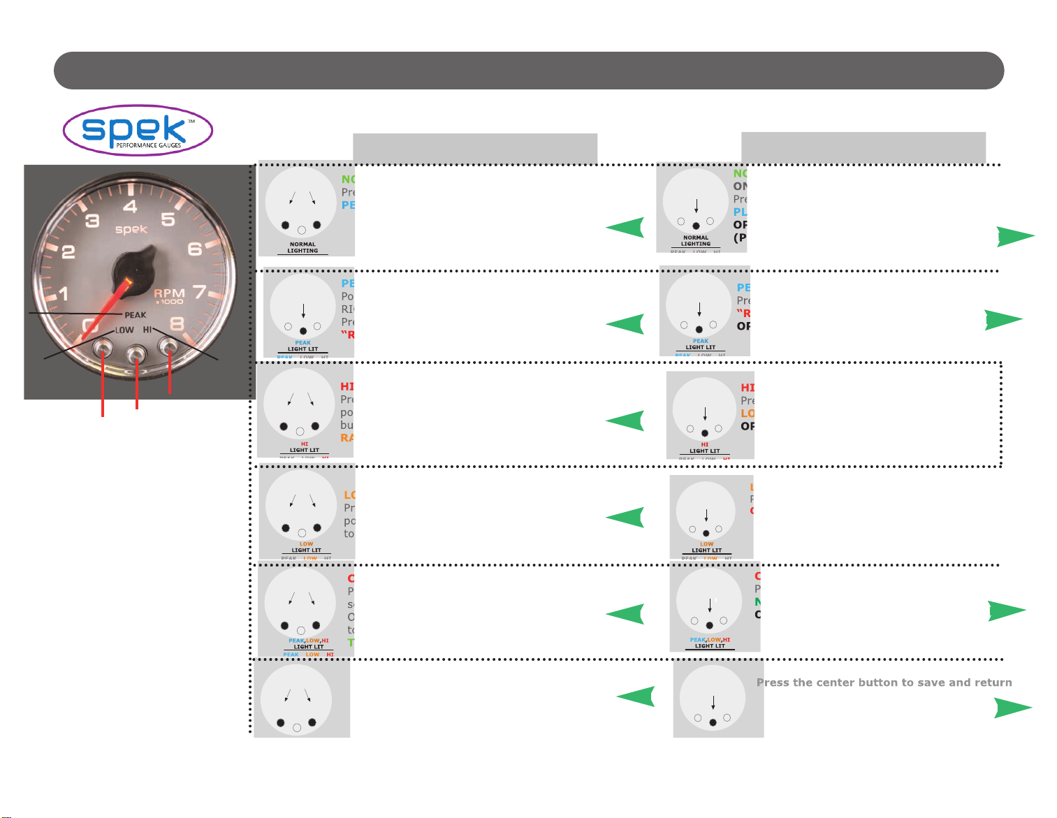
PROGRAM MAIN MENU
START HERE
MAIN MENU
(Press one
button at a time)
NORMAL OPERATION:
Press the center button to save and advance to
PEAK PLAYBACK.
NORMAL
LIGHTING
PEAK LO HI
PEAK PLAYBACK:
Pointer will now display peakplayback. Press the
RIGHT or LEFT button to adjust dial brightness.
Press the center button to advance to HIGH
“RACING” RED-LINE SETTING.
HIGH “RACING”RED-LINE SETTING:
Press the RIGHT or LEFT button to move dial
pointer to the high setting. Press the center
button to save and advance to LO
RACING YELLO -LINE SETTING.
HI
LIGHT LIT
PEAK LO HI
LO RACING YELLO -LINE SETTING:
Press the RIGHT or LEFT button to move
pointer to low SETTING. Press the center but-
ton to save and advance to COLORSCHEME.
COLORSCHEME:
Press down and up buttons to select a color
scheme. ( FF-VI LET-BLUE-GREEN-YELL W-
RANGE-RED-WHITE). Press the center button
to save and advance to NORMAL OPERA-
TION.
NORMAL OPERATION:
ON PO ER UP THE GAUGE READS THE RPM.
Press the center button to save and advance to PEAK
PLAYBACK.
OPTION: SELECT PULSES PER REVOLUTION
(PPR)
NORMAL
LIGHTING
PEAK LO HI
PEAK PLAYBACK:
Press the center button to advance to HIGH
“RACING” RED-LINE SETTING. R
OPTION:RESTORE FACTORY DEFAULT
HIGH “RACING”RED-LINE SETTING:
Press the center button to advance to
LO RACING YELLO -LINE SETTING.
OPTION:SET THRESHOLD ALERT SIGNAL
HI
LIGHT LIT
PEAK LO HI
COLORSCHEME:
Press the center button to advance to
NORMAL OPERATION. R
OPTION A:DEMO MODE
Down
Button
PEAK
LO HI
Up
Button
Mode
Button
TACHOMETER
NORMAL MODE
PRESS ONE
AT A TIME
D WN
-UP
+
PRESS
PRESS ONE
AT A TIME
D WN
-UP
+
PRESS ONE
AT A TIME
D WN
-UP
+
PRESS ONE
AT A TIME
D WN
-UP
+
PRESS
PRESS
PRESS
PRESS
Flow Chart Programming Instructions for : RPM TACHOMETER 2 1/16” CONTROLLER
Patent Pending All Rights Reserved
PRESS ONE
AT A TIME
D WN
-UP
+
PRESS
Dial Brightness:
Press down and up buttons to adjust dial bright-
ness. Press the center button to save and return
to N RMAL PERATI N
Dial Brightness:
to NORMAL OPERATION. R
OPTION: POINTER BRIGHTNESS

Flow Chart Programming Instructions for : RPM TACHOMETER 2 1/16” CONTROLLER
SUBMENU
(ENTER FROM MAIN MENU)
(Press two(2) buttons simultaneously for 5 seconds)
OPTION:RESTORE FACTORY DEFAULT:
While in PEAK PLAYBACK, press and hold the
center and right buttons for five seconds. Dial
pointer will step five times and return to zero.
This will erase all user-programmed calibrations
and settings, and return to NORMAL OPERA-
TION.
PEAK
LO
HI
OPTION: SELECT PPR (Pulses Per Revolution)
The WHITE/DIMMER circuit must be installed and produce 12vdc before PPR
can be programmed. While in NORMAL OPERATION, press and hold center
and right buttons for 5 seconds. Dial will flash blue rapidly. Press down and up
buttons to select PPR value by moving dial pointer to corresponding RPM. Press
the center button to save and return to NORMAL OPERATION.
(See PPR Chart Page 4-5)
OPTION :POINTER BRIGHTNESS:
While in DIAL BRIGHTNESS, press and hold the
center and left buttons for five seconds to enter
pointer brightness mode. The dial pointer will start
to flash and point to the upper right.
OPTION A:DEMO MODE:
WHILE IN COLORSCHEME, press and hold the center and right buttons for
five seconds. Dial will scroll through the seven color schemes. The HI,LO
and PEAK will light, and the dial pointer will move. Press the center button to
return to NORMAL OPERATION.
OPTION: POINTER BRIGHTNESS:
Press down and up buttons to
adjust the pointer brightness. Press the
center button to save and return to
NORMAL OPERATION
PRESS
BOTH
PRESS
BOTH
PRESS ONE
AT A TIME
D WN
-UP
+
U.S. Patent # 7,612,660 & 7,278,749
PRESS
BOTH
PRESS
BOTH

• Tachometer Gauge 2 1/16” INCH
• Wiring Harness
• Mounting Cup (Not required for pod installation)
• (2) Neoprene EDPM Grommets
PACKAGE CONTAINS:
FEATURES:
SPEK PERFORMANCE GAUGE TACHOMETER FEATURES:
• INTELLIGENT ELECTRICAL GAUGES.
• GAUGES ARE PROGRAMMED THROUGH COMMAND KEYS ON FACEPLATE.
• STEPPER MOTOR DRIVES THE GAUGE POINTER OVER A 280 DEGREE SWEEP.
• WIDE-ANGLE-DIAL™ HAS A 15% LARGER VIEWING AREA ON A 2 1/16” GAUGE.
• PROGRAMMABLE 7 COLOR DIAL AND RED POINTER ILLUMINATION.
• OPTIONAL OUTPUT CONTROL MODULE.
INSTALLATION INSTRUCTIONS:
1 DISCONNECT NEGATIVE (-) BATTERY TERMINAL.
2 VARIOUS MOUNTING SOLUTIONS ARE PRESENTED BY PROPARTS,
DASH INSTALLATION: SELECT LOCATION IN THE DASH TO MOUNT GAUGE AND
CUT A 2 1/16” HOLE. USE A FILE TO INCREASE THE HOLE SIZE IF REQUIRED. BE SURE THERE IS
SUFFICIENT ROOM BEHIND THE HOLE FOR THE METER CASE AND THE CONNECTORS YOU WILL USE.
3 IF A SUITABLE HOLE IN THE FIRE WALL IS NOT AVAILABLE, CUT AN 11/16” HOLE.
4 TWO GROMMETS MUST BE CUT TO PERMIT INSTALLATION OF WIRING HARNESS. (SEE DIAGRAM 1)
5 INSTALL INSTALL THE GROMMET AND MOUNTING CUP ON THE WIRING HARNESS AS SHOWN IN
DIAGRAM 1. GROMMET IS FOR THE HOLE IN THE FIREWALL.
SPEK™ MONITOR AND CONTROL PERFORMANCE GAUGE TACHOMETER
Wiring Installation Instructions for : RPM Tachometer
2 1/16” Controller

6 DO NOT CONNECT WIRING HARNESS TO THE GAUGE UNTIL THE OTHER CONNECTIONS HAVE
BEEN MADE AND TESTED.
7 CONNECT THE RED (+ 12 VOLT SUPPLY) WIRE TO “ON” CIRCUITS THAT GET POWER WHEN THE
IGNITION IS TURNED-ON. THIS CIRCUIT MUST BE FUSED BEFORE THE iGNITION SWITCH (1 AMP,
3AG FAST ACTING).
8 CONNECT THE BLACK WIRE TO A GOOD GROUNDING POINT ON THE CAR’S CHASSIS.
9 CONNECT THE WHITE WIRE TO THE DIMMER VOLTAGE GOING TO THE DASH LIGHTS. THIS WILL
CAUSE THE METER BRIGHTNESS TO TRACK THE BRIGHTNESS OF THE REST OF THE INDICATORS.
THIS CIRCUIT MUST PRODUCE 3 TO 12VDC BEFORE THE PPR CAN BE PROGRAMMED.
10 CONNECT THE SENSING WIRE TO THE PRIMARY TERMINAL ON THE IGNITION COIL
(STANDARD-TYPE COIL) OR TO THE AUXILIARY TERMINAL MEANT FOR THE TACH WIRE (AFTER
MARKET, HIGH PERFORMANCE COIL). DO NOT CONNECT TO COIL ON MSD IGNITION. ATTACH ONLY
TO TACH TERMINAL.
11 PLUG THE WIRING HARNESSES INTO THE GAUGE AND MOUNT IN POD OR DASH.
12 FOR DASH INSTALLATION, ATTACH MOUNTING CUP OVER THE BACK OF THE GAUGE AND HAND
TIGHTEN. DO NOT OVER TIGHTEN. MOUNT CUP BEFORE INSTALLING GROMMET. FAILURE TO DO
SO WILL TWIST WIRES CAUSING A SHORT CIRCUIT.
13 POWER UP THE GAUGE AND INSPECT ALL CONNECTIONS. IF GAUGE IS OPERATING NORMALLY,
PROCEED TO “PROGRAMMING MANUAL”.
2
Wiring Installation Instructions for : RPM Tachometer
2 1/16” Controller

GREEN - TACH INPUT
TACHOMETER
Terminal
Electronic Ignition
.
Black-Chassis Ground
Firewall
Grommet
10-Pin Wiring
Harness & Plug
GAUGE
5-Pin Wiring Harness
3-Pin Wiring Harness OR
CUP
Grommet
Red-12V
Ignition Switch
White-12V
Dash Lighting
HEADLIGHT
SWITCH
Fuse
Grommet
Cut
85
86
87A
30
87
Gauge
PIN 8 Output/Purple
FET
Output
CAUTION: 12 VOLT DC POWER
MUST BE CONNECTED TO THE
IGNITION POWER AFTER A
20 AMP FUSE (USER SUPPLIED)
WARNING: OUTPUT CONTROL MODULE
NOT TO EXCEED 1.5 AMPS AT 12 VOLTS DC.
WARRANTY WILL BE VOID IF INCREASED
OUTPUT VOLTAGE OR CURRENT IS APPLIED.
Optional relay: May use Dedebear
HPR or equivalent.
PROGRAMMABLE LIMIT SETTING .
WHEN A SETTING IS TRIPPED,
AN OUTPUT SIGNAL IS
GENERATED. THIS CAN BE
USED TO SWITCH ON A
RUGGED 35 AMP RELAY
TO ACTIVATE A LOW OIL ENGINE
KILL, ALARMS, CUT THROTTLE
BODY SENSOR TO DEFUEL
KILL BOOST VALVE.
A
TO OUTPUT
CONTROL MODULE
A
TO: RED
IGNITION
SWITCH
+12VDC
WARNING
Warranty will be void if connected to coil when using
an aftermarket ignition box such as, but not limited to
products from the following manufacturers: MSD, Crane,
Jacobs, Mallory, Holley, Etc.. Prior to installation of your
tachometer, check with the ignition box manufacturer for
recommended tachometer signal location.
DIAGRAM 1
PATENTED WIDE ANGLE DIAL
FOR SUPERIOR VISIBILITY
U.S PATENT #7,278,749
3
Wiring Installation Instructions for : RPM Tachometer
2 1/16” Controller
DIAGRAM 2
CAUTION:
DIMMER CIRCUIT MUST
HAVE 3 TO 12VDC TO
PROGRAM PPR.
1 2 3 4 5 6
7 8 9 10 11 12

Wiring Installation Instructions for : RPM Tachometer
2 1/16” Controller
4
THERE ARE THREE SECTIONS TO THIS MANUAL: WIRING INSTRUCTIONS, PROGRAMMING
INSTRUCTIONS AND FLOW CHART PROGRAMMING INSTRUCTIONS. PLEASE READ EACH
SECTION CAREFULLY BEFORE ATTEMPTING TO INSTALL OR OPERATE THIS PRODUCT.
WARNING:
• ALL INSTRUCTIONS IN THIS MANUAL MUST BE FOLLOWED TO INSURE SAFE
INSTALLATION AND OPERATION OF THIS PRODUCT.
• NEVER DISASSEMBLE MODIFY OR TAMPER WITH THIS PRODUCT. THIS COULD CAUSE
DAMAGE AND MAKE THEM UNSAFE TO USE. TAMPERING WITH THE PRODUCT WILL VOID
THE LIMITED WARRANTY.
• INSTALLATION MUST BE PERFORMED BY AN EXPERIENCED AUTOMOTIVE TECHNICIAN.
• INSTALLER MUST USE SAFETY GLASSES.
• DISCONNECT THE NEGATIVE BATTERY TERMINAL BEFORE BEGINNING INSTALLATION.
PROPARTS LLC IS NOT RESPONSIBLE FOR DAMAGE TO ENGINE, VEHICLE OR UNIT CAUSED
BY ELECTRICAL SHORTS.
• DURING INSTALLATION, DO NOT INTERFERE WITH ANY EXISTING CONNECTIONS OR
WIRES.
• ALL ELECTRICAL CONNECTIONS USE SOLDER LESS CONNECTORS AND INSULATE ALL
CONNECTIONS WITH ELECTRICAL TAPE.
• AVOID WIRING NEAR ENGINE, EXHAUST SYSTEM, TURBINE OR ANY AREA THAT MAY
RESULT IN DAMAGE.
• DISCONTINUE USE OF THE PRODUCT IF SMOKE OR A STRANGE ODOR IN PRESENT.
CAUTION
• PROPARTS LLC IS NOT RESPONSIBLE FOR INCORRECT INSTALLATION OR PROGRAMMING
OF SPEK™ GAUGES OR CONTROLLERS.
• SPEK™ GAUGES AND CONTROLLERS ARE DESIGNED FOR 12V DC ELECTRICAL SYSTEMS
WITH A NEGATIVE GROUND.
• DO NOT ADJUST THE GAUGES OR GAUGE PROGRAM WHILE DRIVING
• OBEY ALL RULES AND REGULATIONS OF HIGHWAY AND STREET DRIVING.
• INSTALL SENSOR AND WIRE AWAY FROM HIGH HEAT AND / OR VIBRATION AREAS.
• USE CARE WHEN CONNECTING OR DISCONNECTING THE WIRING HARNESS. PULL OUT
EACH CONNECTOR WHILE PRESSING THE LOCK OF THE CONNECTOR FIRMLY.
• IF THE BATTERY TERMINAL IS DISCONNECTED, THE AUDIO, CLOCK AND OTHER MEMORY
DATA MAY BE LOST. THE NECESSARY DATA WILL HAVE TO BE RESET AFTER INSTALLATION.

Programming Instructions for : RPM Tachometer
2 1/16” Controller
5
DOWN MODE UP
+
–
MAIN MENU
NORMAL OPERATION
PEAK PLAYBACK
HIGH RED-LINE SETTING
LOW THRESHOLD SETTING
COLORSCHEME
DIAL BRIGHTNESS
SUBMENU
OPTION:SELECT PPR
OPTION:RESTORE FACTORY DEFAULT
OPTION: DEMO MODE
OPTION: POINTER BRIGHTNESS
U. S. PATENTS 7,612,660 AND 7,278,749 ADDITIONAL PATENTS PENDING.
Refer to the “Flow Chart Programming Instructions” while reviewing this guide.
Gauge is field programmable by the operator while installed in the vehicle. This programming is
accessed by pressing the control buttons located on the face or the meter dial, ONE AT A TIME.
The “Down” and “Up” buttons move the pointer to a desired setting or controls the faceplate
illumination. The center “Mode” button will save the setting you choose and proceed to the next
level. Pressing the “Mode” and “Up” or “Mode” and “Down” buttons simultaneously and holding
them for 5 seconds in any level will shift you to the Submenu.
SPEK™ MONITOR AND CONTROL PERFORMANCE GAUGE TACHOMETER

PROGRAMMING STARTS IN
MAIN MENU
PRESS PROGRAM BUTTON ONE (1) AT A TIME IN THE MAIN MENU MODE.
1 NORMAL OPERATION:
On power up, the meter usually starts in NORMAL operating mode. The Tachometer will read en-
gine’s RPM. Press the center “mode” button to advance to 2 PEAK PLAYBACK
2PEAK PLAYBACK:
Reads the highest value displayed on the meter since the last time the “Peak” value was displayed.
Pressing the “Down” or “Up” control button will control the gauge dial illumination. Press the center
“Mode” button to advance to 3 HIGH RACING RED-LINE SETTING
3HIGH RACING RED-LINE SETTING:
Sets the point at which “HIGH” warning RED-LINE is reached for that specific gauge. The “Down and
“Up” buttons will move the dial pointer to select “Maximum RED-LINE”. During normal operation the
gauge constantly monitors the sensor value and compares it to the “HIGH” RED-LINE. If the
threshold is exceeded, the red “HI” indicator is turned on and an output signal generated. Press the
center “Mode” button to save the setting and advance to 4 LOW RACING YELLOW-LINE
SETTING
4LOW RACING YELLOW-LINE SETTING:
Set the Minimum RED-LINE: Sets the point at which “LOW” warning threshold is reached for that
specific gauge. The “Down” and “Up” buttons will move the dial pointer to select the LOW
RACING YELLOW-LINE SETTING. During normal operation the gauge constantly monitors the
sensor value and compares it to the “LOW” threshold. If the sensor value drops below the threshold,
the yellow “LOW” indicator is turned on and an output signal generated. Press the center “Mode”
button save the setting and advance to 5 COLORSCHEME
5COLORSCHEME:
Set Faceplate Color Scheme: Operator can select the color of the gauge dial illumination. Each time
you press the “Down” control button you scroll through dial color selection until the dial light goes
off. Then press the “Up” button to reverse the scroll. Select your dial color illumination by pressing
the center “Mode” button to save the setting and advance to NORMAL OPERATION.
6 DIAL BRIGHTNESS:
Adjust the dial brightness for day or evening driving conditions The RIGHT and LEFT command but-
tons will dim or brighten the faceplate illumination. Press the center “Mode” button to save the set-
ting and advance you to NORMAL OPERATION
Programming Instructions for : RPM Tachometer
2 1/16” Controller
6

SUBMENU
SUBMENU IS ACCESSED THROUGH THE MAIN MENU. FIRST GO TO THE APPROPRIATE LEVEL OF THE
MAIN MENU AND THEN FOLLOW THE INSTRUCTIONS IN THE PROGRAMMING FLOW DIAGRAM TO
ENTER THE SUBMENU. PRESS THE “MODE” AND “UP” OR “MODE” AND “DOWN” BUTTONS
SIMULTANEOUSLY FOR 5 SECONDS TO ENTER THE SUBMENU AND ONE BUTTON AT A TIME WHILE
IN THAT SUBMENU.
OPTION:SELECT PPR: (Pulses Per Revolution) Select the PPR value by pressing “Down or “Up”
button to move dial pointer to corresponding RPM. For additional information see the Tachometer
Sense Line Attachment and Meter Setting section on page 4.
OPTION:RESTORE FACTORY DEFAULT: TO RESTORE FACTORY DEFAULTS, PRESS THE
:MODE” BUTTON ONCE TO ENTER THE PEAK PLAYBACK. THEN PRESS AND HOLD THE “MODE” AND
“UP” BUTTONS FOR FIVE SECONDS. Activation of the Default will erase all field calibration setup
settings that are programmed. Factory calibrations will not be affected.
OPTION A:DEMO MODE: Displays the features of the meter. The pointer goes up and down
the scale, the dial colors change and the HI, LOW and PEAK warning indicators light. The Demo
mode does not time out. If the gauge is turned off in the Demo mode, it will start up in the Demo
Mode. Press the “Mode” button to return the gauge to NORMAL operation.
OPTION: POINTER BRIGHTNESS MODE: The “Down” and “Up” buttons adjust the dial
pointer brightness to blend in with original manufacturer’s gauges and the owner’s requirements
Press the center MODE button to save the setting and return to NORMAL OPERATION
PROGRAMMING INFORMATION:
• TO RESET THE PROGRAM TO NORMAL OPERATION FROM ANY MODE PRESS THE “UP” AND “DOWN”
BUTTONS SIMULTANEOUSLY. THIS SOFT RESET CANCELS THE INFORMATION YOU PROGRAMMED IN
THAT MODE ONLY AND RETURN YOU TO NORMAL OPERATION.
• THE FACEPLATE WILL “FLASH” WHEN BUTTONS ARE DEPRESSED TO ACKNOWLEDGE COMMANDS.
• PROGRAMMING ERRORS WILL BE SIGNALLED BY FLASHING THE FACEPLATE LIGHTING “PURPLE”,
“BLUE”, “GREEN” THEN “ORANGE”.
• IF PROGRAMMING IS INACTIVE FOR 60 SECONDS THE MODE WILL TIME OUT AND THE GAUGE
WILL RETURN TO NORMAL OPERATION, EXCEPT FOR THE DEMONSTRATION MODE. THE DEMO
MODE WILL NOT TIME OUT UNTIL THE CENTER “MODE” BUTTON IS PRESSED IF THE GAUGE IS
TURNED OFF IN THE DEMO MODE, IT WILL START UP IN THE DEMO MODE.
Programming Instructions for : RPM Tachometer
2 1/16” Controller
7
TACHOMETER SENSE LINE ATTACHMENTS AND METER SCALING
GASOLINE ENGINES
The WHITE/DIMMER circuit must be installed and supply 3 to 12vdc before the PPR can be
progammed
Attach the sensing line to the primary side of a spark coil, and then set the calibration PPR value for
your spark configuration, using directions for the CALIBRATION option.
Once upon a time, there was just one configuration: a spark coil, a distributor, and then wires from the
distributor cap to the individual sparkplugs. If your car is like this, use the table below:
FOR “CLASSIC” ONE-IGNITION-COIL ENGINES
IF YOU HAVE ONE
COIL PER PLUG CONNECT TO ANY SPARK COIL PRIMARY
IF YOU HAVE ONE COIL PER TWO PLUGS CONNECT TO ANY SPARK COIL PRIMARY
DIESEL ENGINES
Modern diesel engines usually have camshaft sensors or electronic injector pumps. If there is one
injector per cylinder, the signal from the pump drive will be 1/2 PPR. Similarly, if there is a camshaft
sensor signal the signal will be ½ PPR. Set the calibration at a reading of 500.
If there is no electronic cam sensing or fuel injection in your diesel engine, the procedure is more com-
plex. A signal can be obtained from the alternator by attaching a wire directly to the winding of the sta-
tor before it goes to one of the rectifier diodes. This signal will be proportional to engine speed, but the
Programming Instructions for : RPM Tachometer
2 1/16” Controller
8
# PLUG
2
4
6
8
10
12
PULSES PER
REVOLUTION (PPR)
1
2
3
4
5
6
METER
SETTING
1000
2000
3000
4000
5000
6000
# PLUG
Any
PULSES PER
REVOLUTION (PPR)
1/2
METER
SETTING
500
# PLUG
Any
PULSES PER
REVOLUTION (PPR)
1
METER
SETTING
1000
This manual suits for next models
2
Table of contents
Popular Measuring Instrument manuals by other brands


SBC
SBC Saia PCD ALD1D5FM Assembly and operating instructions

Cantium Scientific
Cantium Scientific MicroBio MB2-RSH Installation and Operation Supplement

GE
GE DigitalFlow DF868 Programming manual

ERT
ERT AM3 Instructions for use

Rohde & Schwarz
Rohde & Schwarz R&S NRX Series Getting started

TESTO
TESTO 550 quick start guide


