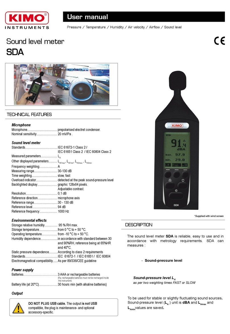
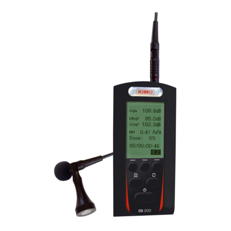
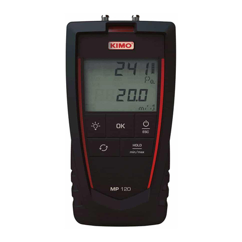
Kimo DS300 User manual

1
DS300
Noise dosimeter

Table of contents
1 Introduction........................................................................................................................................................................ 4
1.1 Presentation............................................................................................................................................................... 4
1.2 Main features............................................................................................................................................................. 4
2 General points.................................................................................................................................................................... 5
2.1 Regulatory.................................................................................................................................................................. 5
2.2 Labour law................................................................................................................................................................. 5
2.3 Measure ent............................................................................................................................................................. 5
2.4 Noise exposure – Exposure points............................................................................................................................ 5
3 Vocabulary......................................................................................................................................................................... 5
4 Operating principle............................................................................................................................................................. 7
4.1 Keyboard.................................................................................................................................................................... 7
4.2 Screen........................................................................................................................................................................ 7
5 Set the instru ent.............................................................................................................................................................. 8
5.1 Adjust the contrast / backlight.................................................................................................................................... 8
5.2 Measure ent progra ing....................................................................................................................................... 8
5.3 Reading...................................................................................................................................................................... 8
5.4 PC.............................................................................................................................................................................. 9
5.5 Configuration.............................................................................................................................................................. 9
5.6 Battery life.................................................................................................................................................................. 9
5.7 Instru ent.................................................................................................................................................................. 9
5.8 About.......................................................................................................................................................................... 9
6 Measure ent odes......................................................................................................................................................... 9
6.1 General synoptic...................................................................................................................................................... 10
6.2 Deter ination of the daily noise exposure............................................................................................................... 11
7 Calibrate the instru ent................................................................................................................................................... 12
7.1 Free field coefficient................................................................................................................................................. 12
7.2 Modification of the value of the reference source..................................................................................................... 12
7.3 Calibration................................................................................................................................................................ 12
7.3.1 Calibration of V1 channel................................................................................................................................. 12
7.3.2 Calibration of V2 channel................................................................................................................................. 13
7.3.3 Calibration of D-MB icrophone...................................................................................................................... 13
8 Classical sound level eter............................................................................................................................................. 14
8.1 Settings before perfor the easure ent............................................................................................................... 14
8.2 Perfor a easure ent.......................................................................................................................................... 14
9 Analyzer integrating-averaging sound level eter............................................................................................................ 15
9.1 Setting before perfor ing the easure ent............................................................................................................ 15
9.2 Perfor a easure ent.......................................................................................................................................... 16
9.2.1 Explicative synoptic of the START/STOP ode...............................................................................................16
9.3 Consult values......................................................................................................................................................... 17
10 Analyzer avereger integrator sound level eter............................................................................................................. 17
10.1 Settings before perfor the easure ent: range selection...................................................................................18
10.2 Measure ent in progress: V1 channel................................................................................................................... 18
10.3 Measure ent in progress: V1 + V2 channels........................................................................................................ 20
10.4 Measure ent in progress: V1 channel and frequency analysis with filters by octave bands fro 63 Hz to 8 kHz.21
10.5 Measure ent in progress: V1+V2 channels and frequency analysis with filters by octave bands fro 63 Hz to 8
kHz................................................................................................................................................................................. 22
10.6 Measure ent in progress: audio recording on threshold.......................................................................................23
10.6.1 Te poral synoptic.......................................................................................................................................... 24
10.6.2 Synoptic of the anage ent of the recording dyna ic.................................................................................25
10.6.3 Use of audio recording................................................................................................................................... 26
10.6.4 : Measure ent in progress – Data reading.................................................................................................... 27
10.7 Measure ent launching......................................................................................................................................... 28
10.7.1 I ediate ode............................................................................................................................................ 28
10.7.2 Delayed ode................................................................................................................................................ 28
10.7.3 Repetitive delayed ode................................................................................................................................ 29
10.7.4 Free delayed ode........................................................................................................................................ 31
10.7.5 Delayed ode – easure ent wait............................................................................................................... 31
10.7.6 Delayed ode – leave wait o ent and stop the progra ing...................................................................31
10.8 Stop the easure ent........................................................................................................................................... 32
10.9 Data processing..................................................................................................................................................... 33
10.10 Data reading........................................................................................................................................................ 33
10.11 Reading in V1 channel ode............................................................................................................................... 34
2

10.12 Reading in V1+V2 channels ode....................................................................................................................... 35
10.13 Reading: V1 channel ode and frequency analysis with filters by octave bands fro 63 Hz to 8 kHz................36
10.14 Reading: V1+V2 channels ode and frequency analysis with filters by octave bands fro 63 Hz to 8 kHz.......37
10.15 Files transfer....................................................................................................................................................... 38
10.16 Delete files........................................................................................................................................................... 38
11 Running infor ation....................................................................................................................................................... 39
11.1 Instantaneous overload – percentage.................................................................................................................... 39
11.2 Power supply.......................................................................................................................................................... 39
11.3 Over range easure ent...................................................................................................................................... 39
11.4 Detection and counting of peak pressure levels 135-137-140 dB..........................................................................39
11.5 Alar s.................................................................................................................................................................... 41
11.6 Auto Off.................................................................................................................................................................. 41
11.7 LCD locking............................................................................................................................................................ 41
11.8 Stop locking – waiting ode................................................................................................................................... 42
12 Maintenance.................................................................................................................................................................. 43
12.1 Care....................................................................................................................................................................... 43
12.2 Regular checking................................................................................................................................................... 43
12.3 Load the battery..................................................................................................................................................... 43
13 Preparing for easure ent........................................................................................................................................... 43
13.1 Preparing the instru ent........................................................................................................................................ 43
13.1.1 Channel V1 easure ent only...................................................................................................................... 43
13.1.2 Measure ent with V1 and V2 channels......................................................................................................... 44
13.1.3 Wearing the instru ent.................................................................................................................................. 44
13.1.4 Fixing the icrophone.................................................................................................................................... 44
13.1.5 Using the windscreen..................................................................................................................................... 45
14 Technical features.......................................................................................................................................................... 46
14.1 Standards............................................................................................................................................................... 46
14.2 Metrology............................................................................................................................................................... 46
14.3 Charger for battery................................................................................................................................................. 46
14.4 Di ensions – Weight............................................................................................................................................. 46
14.5 Audio recording capacity........................................................................................................................................ 47
14.6 Battery life.............................................................................................................................................................. 47
14.7 Delivery and packaging.......................................................................................................................................... 47
14.8 Optional and accessories....................................................................................................................................... 47
3

1 Introduction
The noise dosimeter is a measuring instrument allowing measurement of noise exposure at workstation. Its
advanced features make easier the investigation to determine and reduce noise pollution:
➢frequenc anal sis b octave band for an optimal choice of protections
➢two-channel dosimeter for simultaneous measurement of exposures suffered b the ears
➢audio recording of noise sources on thresholds for a better identification
In accordance with international standards, instrument calculates values usuall used to compare with exposure
regulator values.
Thanks to its memor , instrument stores measurement event timers which are then transferred to a computer and
processed with software, supplied with the instrument.
software supplied as option allows an anal sis more detailed as per NF EN ISO9612: 2009 standard.
In addition, this noise dosimeter has a classical sound level meter and anal zer integrating-averaging function for a 1st
estimation of the noise environment of the workstation.
1.1 Presentation
comes in the shape of a little case with ergonomics forms. It can be easil positioned on the belt or in a cloth pocket
of people at their work station. the microphone at the end of extension is fixed thanks to a kit speciall designed to minimize
perturbations created b chocks or cloth frictions.
Measurements are stored in a microSD card memor of big capacit giving the whole an almost unlimited measurement
capacit .
With its graphic backlighted LCD screen, is also a classical sound level meter and an integrating-averaging anal zer
for a fast noise estimation at workstation.
During measurement, if necessar , it can advised people about levels through a two-coloured light.
1.2 Main features
Noise dosimeter and classical sound level meter and integrating-averaging anal zer with graphical backlighted LCD screen
with:
•microphone with extension t pe electret of diameter 3/8'' (9.52 mm) of little size allowing a reliable fixation
•2 measurement channel: side and side (microphone and fixing kit for channel 2 as option)
•3 d namic ranges:
- in running mode, one measurement channel: 40-140 dB range
- in running mode, two measurement channels: 40-120 dB or 60-140 dB ranges
•Simultaneous measurement of Leq and LpK:
- Leq: with A and C weightings and b octave band filters from 63 Hz to 8 kHz
- LpK: with C or Z weightings
•Management of overange of peak pressure levels 135-137-140 dB
•Audio recording on thresholds of noise sources
•Dela ed and/or repetitive measurement start
•Ke board protection during measurement and against unwanted stops
•Active or inactive LCD screen, visual alarms
•Calculation and results in accordance with NF EN ISO9612: 2009 standard
•Storage capacit : 99 event timer of more 24h each
Li-Ion batter for a batter -life better than 28 hours (according measurement programming). All of the setting of is
directl performed with the ke board or with the LDS300 software.
4

is supplied with the software which allows to transfer easil data to a computer to:
•visualize measurement data globall or more detailed
•process areas of non-measurement (break, beginning and end of measurement,...)
•customize report for saving and printing
2 General points
2.1 Regulatory
The 2003/10/CE European Guideline makes mention of instructions regarding the exposure of workers to risks. The
regulator requirements define a control context of noise pollution in work place. From these controls, the obtained results
are compared with defined regulator action thresholds.
These thresholds are based on two parameters:
•the dail noise exposure level Lex,8 hours in dBA
•the LCpeak peak pressure level C-weighted
When thresholds are exceeded, actions have to be led.
The regulator specifies two action thresholds causing preventive actions:
•the lower exposure value –
•the upper exposure value –
These two thresholds are completed b a third one called TLV, threshold limit value , which should not be exceeded in an
case, with or without protection (PICB): !"
2.2 Labour law
It relies mainl on #!!$, #!!$ and #!!$ articles and completed b the decree of the %&'().
2.3 Measurement
It relies mainl on #!!$, #!!$ and #!!$ articles and completed b the decree of the %&'().
Measurement can be made according prescriptions of the NF EN ISO9612: 2009 standard.
The standard recommends three measurements wa s:
•b task
•b work or function
•b full da
This standard also specifies the measurement processing including the estimate of measurement uncertaint .
2.4 Noise exposure – Exposure points
This simplified wa is especiall adapted for workers whose position is constituted b several identifiable tasks. The
difficult to totalize levels dB does not allow a fast approach of the dail noise exposure, using this wa brings a ver
significant operating flexibilit .
It takes into account the noise exposure expressed in Pa²h of the several tasks that can be then add to get a global noise
exposure during the work da . From this, the determination Lex,8h dail exposure becomes easier b search in a dedicated
corresponding table. This table is available in the ED6035 document edited b the INRS.
calculates the noise exposure and directl displa s on its screen the number of exposure points regarding the task
performed b the worker to his position.
3 Vocabulary
*: A-weighted sound level pressure, fast time weighting (*ast) – range: 40-140
: A-weighted sound level pressure, fast time weighting (low) – range: 40-140
+: peak pressure level in reference with 20µPa C-weighted
,+: peak pressure level in reference with 20µPa Z-weighted (Lin)
5

RST: reset of calculations of maximum or minimum values memorized – erasing of measurement session or of the whole
memor .
-": save and store data in the microSD card
./ programmable duration of elementar integration from 1 s to 60 s for the calculation of the equivalent continuous level
stored in the memor
0./A-weighted equivalent continuous level on DI duration
0./C-weighted equivalent continuous level on DI duration
10.: A or C-weighted equivalent continuous level on DI duration or filtered b octave band from 63 Hz to 8 kHz DI
duration.
02/A-weighted equivalent continuous level on the total duration of measurement T
02/2-weighted equivalent continuous level on the total duration of measurement T
102/ or C-weighted equivalent continuous level on the total duration of measurement
: A-weighted dail exposure level
32: noise exposure on the measurement duration T in Pa²h
3: noise exposure on the standardized duration of 8 hours in Pa²h
-4: Noise dose in % - Reference: 85dBA during 8 hours
5: reference level for the calculation of the dose: 85dBA
25: duration reference for the calculation of Lex,d and dose: 8 hours
6": exposure points - 1 exposure point = 0.01Pa²h
$ $!: s mbols for the detection of peak pressure levels of 135-137-140 dB
11: order number of event timers (or session). XX is limited 99.
37: order number of the screens. Y goes from 1 to 6.
: measurement start date. Format: 00/00/00
8: measurement beginning time. Format/00:00
/ measurement end date. Format/00/00/00
8: measurement end time. Format/00:00
9$9/5:4':
$;: microphone name
<<: simultaneous measurement according A and C frequenc weightings
<<<<)8=$8=: simultaneous measurement according A and C frequenc weightings and filters b octave band from 63
Hz to 8 kHz
<//: measurement duration format in da s/hours:minutes:seconds
// current time format in hours:minutes
<<: date format – JJ/MM/AAAA
/: current time format in hours:minutes
:: two-coloured visual alarm for detection
'-: audio recording on exceeded thresholds
'->: automatic stop of the instrument when it is stopped
9"5: LCD screen locking
9"-/locking of the Stop function during measurement
#: reference level for calibration
": free field correction term in calibration mode
;:: number of possible session
6

4 Operating principle
4.1 Keyboard
Turn on the instrument, three modes of operating are available. These modes are accessible with , and ke s. ke
allows to go to reading settings or data transfer screens. !( is used to back to start screen from an mode.
During measurement, ! ke also allows to leave the current screen.
① ② ③ *'5-(4/(5(- texts of the LCD screen situated at
the top and allow to choose the measurement mode and setting.
④ 3(: allows to leave current screen
⑤ 5(: allows to go to others different screens from measurement screens
⑥ <4-(
.:--: $$ (4 are representative of the text or logo situated on the top in the
screen, which means :
: the measurement is in progress
: the measurement is finished or will be launched
4.2 creen
Three screens represent the different measurement and calibration modes et accessible with 1, 2 and 3 ke s.
Pressing (shows the screen for the choice of the different available settings. Move the cursor with ?-@4A buttons
then validate with the ("
7
Anal ser dosimeter-
exposimeter with storage
Classical sound level meter
and frequenc anal zer Calibration
min.
"!
max
""
Raz
/"
LAF
9
dB
9
") "
0.
%") %"
0.
%)" "
<//
40
0,5s
A C 63 250 1k 4k
140
120
100
080
060
040
10/"
125
# /
"/"
99
$" "
%!"
B-

5 Set the instrument
The setting of the instrument contains all the useful and necessar operations for a good processing of
measurement, reading of results or data transfer. It also gives information about the correspondence
with international standards, about the constitutive elements of the instrument and the date of the last
check.
Measurement settings are automaticall saved and reappointed in the next measurement.
5.1 Adjust the contrast / backlight
To optimize the reading of the displa :
➢Adjust the contrast pressing and '5-(4.
➢Activate backlight of the LCD screen for an eas reading in a dark place.
No indicates without backlight and yes its activation. In this last case, battery life is reduced
by about 5%.
Additional information:
- a brief press on tart/ top key allows to activate backlight at any time. ame thing to deactivate it.
- in dosimeter integrator, backlight will deactivate automatically after a few moments to protect battery
life.
5.2 Measurement programming
Measurement programming has to be performed before launching measurement. Adjust settings according conditions and
adopted measurement strateg .
➢Press ( to move the cursor then modif the proposition in inverted video b pressing or
(4.
•9/ concerns the number of measurement channel: V1 or V1 and V2.
•+/chooseC or Z for the weighting of the peak pressure level weighting. Usuall , C
weighting is preferred.
•/ choose the duration of elementar integration of the equivalent continuous level for a good
representation of the temporal evolution of the measurement. This duration goes from 1 s to 60
s b step of 1 s. Usuall , a duration of 1 s is selected.
•<</Two possibilities are suggested:
- the simultaneous measurement of Leq with A and C weightings select << element.
- the simultaneous measurement of Leq A and C weightings and filters b octave band from 63 Hz to
8 kHz: select <<<<)$8=element.
•:/it is about the illumination of the lights situated on the top of the housing visible b the holder of the
dosimeter-noise dosimeter or the technician in charge of the measurement monitoring. Choose(4or-to make
them visible or not.
•'-: select (4 to perform during the measurement a recording on threshold exceeded. In
this case, press ( to select on the screen:
- the reference used: 0-
- threshold be ond which the recording begins. Set this threshold with and
(4with a step of 1 dB.
- the digital bonus of the recorder for optimization of the re-listening. Adjustable with
and ke s among values: !$$)$!$!$! (see page 24)
8
"
C-
35
-"<#D-
6-":4'
5'
6
-'-
'--:
.4':
--4"""
>+
9/
/
./4
<<<<)$8=
:/-'
'-/-'
$$<$$
'-/EF
$ #/0
$ '/
$ G/!
$ ;/%"
$ :/%"
85.0

5.3 Reading
This screen allows to go to the main results of the different event timers stored
in the memor of the instrument.
➢Scroll with or ke s the number of event timers to get the number of
the required event timers.
The screen gives information about dates and times of beginning and
ends of measurement and about measurement settings.
➢Then press ke to read lire all of the other results.
➢Scroll with ke the different screens in connection with event timers.
➢Leave the event timers pressing !ke .
5.4 PC
From this screen, it is possible to clear the memor of the instrument pressing ke . A second press is
necessar to validate this action.
In case of change of mind or error, press ! ke to stop this sequence.
Connect to the computer with USB cable.
5.5 Configuration
From this screen, use the arrow to move the cursor in the required area and modif with and ke s the proposition. The
different settings are:
•'4/ French or English
•'->/ es or no. If es is selected, the instrument will stop after 15 min of non-use. This
allows to save batter life in case of omission to stop if no measurement is launched (see
page 37).
•9"-/ es or no. If es is selected, unwanted stop of measurement in storage is impossible.
•9"5: es or no. If es is selected, LCD screen is off 60 seconds after the launching of
measurement in storage mode.
To reactivate these two functions, enter a code with ke pad (see pages 30 - 37). If no is
selected, the two functions are functional.
•: update the date: da , month, ear
•2:/ update the time: hours, minutes
5.6 Battery life
Autonom gives information about the remaining memor capacit expressed in measurement period
and the measurement duration according the remaining batter capacit (estimation linked to batter
ageing et ambient conditions):
3:/ 96 means that the instrument can still perform 96 measurement event timers (1
measurement = 1 work station).
5.7 Instrument
This screen gives information about the main constitutive elements of the noise dosimeter:
•instrument and its serial number.
•microphones serial numbers (V1 or V1 and V2 and D-MB according to the case)
•the firmware version number
5.8 About
This screen gives information about the origin of manufacture, standards reference of the product and dates of last and next
checks.
9
/<<%
8//
/<<%
8//
./4
9/$
<<<<)$8=
'-/-
/<<%
8//
/<<%
8//
./4
9/$
<<<<)$8=
'-/-
E1
/4
'->/-'
9"-/-
9"5/ -
/
< <
8'/
/
6
Raz
$ ;:/%)
$ /H
$ 'D/
!8

6 Measurement modes
has two operating modes with calibration function in addition:
•Classical sound level meter mode and integrating-averaging anal zer @-'4- for a fast measurement.
•Integrating-averaging noise dosimeter, anal zer @4- for a stud of dail exposure.
These functions are available from home screen: just press , or ke s associated with pictograms.
6.1 General synoptic
10
445sound level
meterEF
Integrating-averaging sound
level meter anal zer
C-$4- sound
level meter
Sound level meter dosimeter anal zer
@4- Calibration
①②③
9
dB
9
") "
0.
%") %"
0.
%)" "
<//
40
# /%!"
"/"
9
%!"
$"
<!<
V1
B-
Cal.
min.
"!
max
""
Raz
/"
LAF
0,5s
A C 63 250 1k 4k
140
120
100
080
060
040
10/"
125
E2
A C 63 250 1k 4k
140
120
100
080
060
040
V1
10/"
125

6.2 Determination of the daily noise exposure
Available possibilities (see options list page 43) of are based on the level of required investigation and on the
adopted measurement methodolog .
So it is possible to:
•Measure on one or two channels simultaneousl to determine the most exposed ear.
•Perform a a frequenc measurement with filters b octave bands from 63 Hz to 8 kHz on one or two channels. This
anal sis allows the optimum choice of personal protector against noise (PICB)
•Make from the channel 1 audio recorders on LAeq or LCpk levels exceeded for a better identification of noise
sources.
•Perform temporal settings:
➢Multiple starts and stops on a work station in connection with identified tasks or samples linked to the end-user
function.
➢Multiple starts and stops on a weekl work station.
C-/according programmings, some metrological features of the noise dosimeter are adjusted.
From ② ke :
One measurement channel: V1 with following features:
•/ exclusivel V1
•;5--/ black sleeve or housing microphone D-MB
•(:5/ extended 40-140 dB
•I4$4/A//C or A//C//63Hz-8kHz
•'-5--4-/ on V1 channel, es or no – see table page 43
•:/ on V1 channel, es or no
•45/off and locked, es or no
•;:-(55(/ 99 measurements of 24 hours minimum
•'--:(/see table page 43
•;4':4-/ protected, es or no
Or
Two measurement channels: V1 and V2 with following features:
•95/ B54J microphone or housing microphone D-MB
•95/ B'4J microphone
•(:5/ industrial 60-140 dB or service sector 40-120 dB
•I4$4/A//C or A//C//63 Hz - 8 kHz
•'5--4-/ on V1 channel, es or no – see table page 43
•:4/on V1 and V2 channels, es or no
•45/ off and locked, es or no
•;:-(55(/ 99 measurements of 24 hours minimum
•($/seetableau page 43
•;4':4-/ protected, es or no
11
Cal.
①②③

And for both t pes of measurement (1 or 2 channels):
2:-4-:4':'5/
•::4/ manual
•(444-4/ dail measurement
•(J444-4/@(:4': (repetitive dail time)
•4444-4E@4-@-(F/ tasks or samples or weekl measurement (progressive dail
time)
12

Calibrate the instrument
Before each measurement series, a calibration must be perform with an appropriate calibrator. A control will be also perform
at the end of the measurement. The interval between both calibrations should not differ from more 0.5 dB. If not, performed
measurements are questionable.
7.1 Free field coefficient
A sound reference source, calibrator or pistonphone, supplies a sound level pressure. During a measurement in free field,
phenomenons of diffraction due to microphone, housing and proximit of obstacles come to disrupt the measurement. This
disruption is minimized if the microphone is awa from the housing.
For , correction in free field linked to microphone is insignificant and close to. This induces b the proximit of
the microphone with the bod of the person who wears the microphone is ver complex and can not be expressed as free
field correction but more reasonabl as measurement uncertaint linked to microphone wearing.
So the ". free field correction reminded and unavailable on the screen is: ".
7.2 Modification of the value of the reference source
➢Select " pressing ke from start screen.
The screen below appears.
The reference value pre-programmed during the manufacture of the instrument shows a priori that
we are using a calibrator of nominal value of 94 dB (1000 Hz). Other values that can be meet: 110
dB – 114 dB and 124 dB.
C-/the measuring is performed on the range 60-140 dB and in C-weighting, it is possible to use a
calibrator or a pistonphone delivering a frequenc of 250 Hz at a level of 124 dB without modification
of free field correction.
.
➢The cursor is on #.
➢Adjust the value dB b dB with K and $ke s.
This value stays memorized until next change.
7.3 Calibration
➢Insert into the calibrator the adapter ring supplied with the instrument.
It has to come to a stop down of the calibrator housing.
➢Insert the microphone until the microphone comes to a stop down of the ring.
This move has to be done slowly and smoothly so as not to damage the microphone.
Prefer to put vertically the sound level meter and the microphone.
➢Begin the procedure of calibration of the instrument as specified in the calibrator user manual.
Note: during calibration, avoid hard environmental conditions: ambient noise, shocks given involuntarily.
7.3.1 Calibration of V1 channel
➢Select " pressing ke from start screen.
➢Check that the reference value corresponds to the one of the used calibrator.
➢Turn on the calibrator and put it on the microphone of V1 channel.
.:-/ put the cursor on 9 when using in mono channel.
The instrument automaticall adjusts the gain of chain to get the coincidence of levels displa ed in #
and 9.
When the measurement is stabilized, a pictogram >+ appears to validate. Press ke .
13
# /
"/"
99
$"
%!"
B-
# /%!"
"/"
%!"
$"
<!<
V1
B-
>+

At this moment, the correction value of the gain and the calibration date are memorized and visible for the next calibration.
➢Press ! ke to leave calibration function.
7.3.2 Calibration of V2 channel
9 channel is accessible onl if it is selected before in the ?;4':-::Amenu.
➢Turn on the calibrator and put it on the microphone of 9channel (blue sleeve).
➢Put the cursor on 9.
The instrument automaticall adjusts the gain of chain to get the coincidence of levels displa ed in
# and 9.
When the measurement is stabilized, a pictogram >+ appears to validate. Press ke .
At this moment, the correction value of the gain and the calibration date are memorized and visible for
the next calibration.
➢Press ! ke to leave calibration function.
7.3.3 Calibration of D-MB microphone
$; housing microphone must be put on 9channel"It is automaticall detected and $; inscription is displa ed and
information of previous calibration (correction and date).
➢Turn on the calibrator and put it on the microphone.
➢Put the cursor on $;.
The instrument automaticall adjusts the gain of chain to get the coincidence of levels displa ed in
# and $;.
When the measurement is stabilized, a pictogram >+ appears to validate. Press ke .
At this moment, the correction value of the gain and the calibration date are memorized and visible
for the next calibration.
➢Press ! ke to leave calibration function.
G-/ the correction can not exceed K<$ for . If the correction to be made exceedsK<$, the
coincidence of values in and is not obtained. >+ pictogram is not displa ed. You have to look for the reason of this
difference: wrong calibrator positioning – defective batter – damaged microphone.
14
# /%!"
"/"
%!"
$"
<!<
V2
B-
>+
# /%!"
"/"
%!"
$"
<!<
;
B-
>+

8 Classical sound level meter
Before each measurement, it is recommended to calibrate the instrument (seepage 13).
➢Press ke from start screen.
➢Press another time ke to perform a fast measurement in classical sound level meter.
instrument processes the sound pressure signal and displa s at the same time the following information:
•the temporall weighted sound pressure level
•maximum and minimum values of levels on the measurement duration
•the maximum peak level of sound pressure on the measurement duration
The used d namic range allows a measurement from 40 to 140 dB without switching.
8.1 ettings before perform the measurement
➢Choose the time constant pressing ke several times.
For A-weighting frequenc , the instrument proposes the measurement according two time constants: fast (F) or slow (S).
Possible choices are:
•*/d namic range 40-140 dB – A-weighting frequenc – F fast temporal weighting
•/ d namic range 40-140 dB – A-weighting frequenc – S slow temporal weighting
C-/ C or Z frequenc weightings of sound pressure peak level must be selected in ?;4':-::A
menu.
8.2 Perform a measurement
Measurement is immediate.
During measurement, two actions are possible:
•reset memorized levels.
•hold measurement thanks to pause function.
To 4 all the values:
➢Press ke (#=pictogram),resetting affects:
•*ormaximum and minimumlevels
• maximum peak pressure value
•information about overload
•6'4 function allows to stop the measurement in progress to avoid unwanted events or to perform a manual
report of results.
➢Press ke (hold pictogram)
➢Press again ke to back to measurement.
➢Leave classical sound level meter function and back to à home screen pressing !ke .
15
①①
Cal.
min.
"!
max
""
Raz
/"
LAF

9 Analyzer integrating-averaging sound level meter
Before each measurement, it is recommended to calibrate the instrument (seepage 13).
➢Press ke from start screen.
➢Press ke to perform a fast measurement in anal zer integrating-averaging sound level meter.
processes sound pressure signal and displa s simultaneousl the following results:
•A and C weighted LXeq equivalent continuous levels and filtered b octave bands from 63 Hz to 8 kHz on an
elementar duration of 0.5 s.
•A and C weighted LXeq equivalent continuous levels and filtered b octave bands from 63 Hz to 8 kHz on a T
elementar duration.
•Maximum and minimum values of equivalent continuous levels of duration of 0.5 since the beginning of
measurement.
•Maximum peak level of LCpK sound pressure on T measurement duration.
9.1 etting before performing the measurement
The used d namic range allows a measurement from 40 to 140 dB without switching.
C or Z frequenc weighting of sound pressure peak level must be selected in ;4':-:: menu.
9.2 Perform a measurement
The screen displa s continuousl , as spectral representation:
•10/ the equivalent continuous levels 0.5 s. A and C weighted and filtered b octave bands from 63 Hz to 8 kHz
Launch measurement on a 2 free duration according to the <- principle:
➢Press ke ( pictogram) to start the measurement on a T duration.
➢Press again ke ( pictogram) to stop measurement.
➢Measurement values are reset with a new press on (( pictogram).
➢Press ke to launch a new measurement ( pictogram).
During or at the end of the measurement:
➢Consult the different screens and LXeq,0.5 s, LXeq,T values and minimum and maximum values (maximum and
minimum spectrum) pressing ke .
➢Leave the anal zer integrating-averaging sound level meter function and back to home screen pressing !ke .
16
① ③
Cal.
0,5s
A C 63 250 1k 4k
140
120
100
080
060
040
10/"
125

9.2.1 Explicati e synoptic of the START/STOP mode
17
T
A C 63 250 1k 4k
140
120
100
080
060
040
10/"
125
Max
A C 63 250 1k 4k
140
120
100
080
060
040
10/!")
125
min
A C 63 250 1k 4k
140
120
100
080
060
040
10/!"%
125
0.5s
A C 63 250 1k 4k
140
120
100
080
060
040
10/"
125
0,5s
A C 63 250 1k 4k
140
120
100
080
060
040
10/"
125
T
A C 63 250 1k 4k
140
120
100
080
060
040
10/"
125
Max
A C 63 250 1k 4k
140
120
100
080
060
040
10/!")
125
min
A C 63 250 1k 4k
140
120
100
080
060
040
10/!"%
125
Control screen
- #4
'
:4':L: press
ke several times to
read the different
screens
3-
:4':L: press
ke several times to
read the different
screens
0,5s
A C 63 250 1k 4k
140
120
100
080
060
040
10/"
125

9.3 Consult values
Screens of T, Max or min. values are available onl if a measurement is launched (press ke ).
Values reading is performed during measurement or at the end of the measurement.
Press ( to go to successivel :
In each screen, press ke to scroll successivel all LXeq,0.5s or LXeq,T or LXeqMax or LXeqMin values.
All the values are reset when a new measurement is launched ( ke : Start/Stop).
➢Press ke . Resetting concerns:
•LXeq,T global levels, LXeqMax, LXeqMin memorized values.
•Overload information (if present).
➢Press ! ke to leave anal zer integrating-averaging sound level meter function and back to home screen.
18
LXeq level is displa ed.
This pictogram recalls the
weighting or the value of filter
b octave band.
Spectrum or graphical dipla of
LXeq values
The cursor moves according to the
weighting or the value of filter b
octave band.
T
A C 63 250 1k 4k
140
120
100
080
060
040
10/"
125
0,5s
A C 63 250 1k 4k
140
120
100
080
060
040
10/"
125
0,5s
A C 63 250 1k 4k
140
120
100
080
060
040
10/"
125
Max
A C 63 250 1k 4k
140
120
100
080
060
040
10/!")
125
min
A C 63 250 1k 4k
140
120
100
080
060
040
10/!"%
125

10 Analyzer avereger integrator sound level meter
Before each measurement, it is recommended to calibrate the instrument (seepage 13).
Measurement settings will have been previousl defined in the ;4':-::menu. This is about:
•use of 1 or 2 measurement channels: V1 or V1 and V2.
•selection of C or Z weightings of sound pressure peak level: usuall C.
•setting of duration of elementar integration of the equivalent continuous level: usuall 1 s.
•measurement of equivalent continuous level simultaneousl with both frequenc weightings A and C and with or
without frequenc anal sis from 63 Hz to 8 kHz.
•activation or not of visual alarms.
•activation or not of audio recording on threshold.
➢From start screen, press ke .
In order to check the proper operating of the measurement chain before launching a measurement, instrument
processes the sound pressure signal and displa s according to the initial programming (V1 onl or V1 and V2):
•the equivalent continuous levels of A and C weighted sound pressure for each duration of each elementar
integration*- LAeq,DI / LCeq,DI
•the peak level of maximum sound pressure of each elementar integration: LCpK
•measurement duration format given in DD/HH:MM:SS
*results are displa ed ion this screen each second. After the launching, results will be displa ed at the rate of the duration of
elementar integration (from 1 s to 60 s).
10.1 ettings before perform the measurement: range selection
The used d namic range is according to measurement mode:
•95:-/ single d namic range 40-140 dB (peak 143 dB)
•9K954:-/ possible selection between 2 d namic ranges pressing ke
40-120 dB: service sector or light industr
60-140 dB (peak 143 dB): industr
The individual dosimeter is a specific instrument wear b a person exposed to sound pollution. Usuall , the reading of
results is made at the end of measurement.
instrument has a special feature: it can be used just as a hand sound level meter de, so partial results during
measurement can be accessible as described below.
19
9/ single range of
40-140 dB
9/ possible ranges :
40-120 dB
60-140 dB
#:-'4
(:5
!for 40-120 dB
)for 60-140 dB
9
dB
9
") "
0.
%") %"
0.
%)" "
<//
40
9
dB
")
0.
%")
0.
%)"
<//
E1
/"
0/%"
0/%"
<//!)
02/%"
02/%)"
E1
V1
40
60

10.2 Measurement in progress: V1 channel
➢From start screen, press ke to scroll screens from 3 to 3!.
➢Press ! ke to back to general screen of measurement.
3/4'445/
•maximum LCpk on T measurement duration
•LAeq,T, LCeq on T measurement duration
•EA,T sound exposure on measurement duration
•Sound dose given in % referenced at 85 dB during 8H00
•Duration of the measurement in progress
3/ detection screen of overloads and values of peak level 135-137-140 dB (see page 36)
3!/remind screen of measurement settings for V1 channel.
10.3 Measurement in progress: V1 + V2 channels
➢From start screen, press ke to scroll screens from 3 to 3!
➢Press ke to go from 945 to 945.
➢Press ! ke to back to general screen of measurement.
20
① key
/<<%
8//
/<<%
8//
./4
9/
<<
'-/-
E4
E1
/"
0/%"
0/%"
<//!)
02/%"
02/%)"
E1
V1
E1
/"
0/"
0/"
<//!)
02/)"
02/%"
E1V2
E3
9
"H
!
V1
/)"
02/"
02/"
32/"6
-4/H
E2
< //
E1
/"
0/%"
0/%"
<//!)
02/%"
02/%)"
E1
V1
Table of contents
Other Kimo Measuring Instrument manuals