ProPlex PPDDS285RP User manual

PRODUCT OVERVIEW
The ProPlex Opto-Splitter PortableMount is designed for standard DMX-512A signal amplification, regeneration,
and splitting to multiple outputs. Just a few features include:
•
Full RDM functionality. RDM defeat switch on each input.
•
Shock-mounted circuitry. Designed for extreme conditions and temperatures.
•
Neutrik™connectors: Locking PowerCon mains and XLR
•
Automatic bit clocking DMX regeneration with less than 1ms lag
•
Outputs switchable between two inputs with LED indicators.
UNPACKING INSTRUCTIONS
Upon receipt of the unit, carefully unpack the carton and check the contents to ensure that all parts are
present and in good condition. Notify the shipper immediately and retain packing material for inspection if
any parts appear to be damaged from shipping or if the carton itself shows signs of mishandling. Save the
carton and all packing materials. In the event that a unit must be returned to the factory, it is important that it
be returned in the original factory box and packing.
POWER REQUIREMENTS
Before powering the unit, make sure the line voltage is within the range of accepted voltages. This unit
accommodates 100-240VAC, 50/60Hz. All units must be powered directly from a switched circuit and cannot
be operated with a rheostat (variable resistor) or dimmer circuit, even if the rheostat or dimmer channel is
used solely for a 0-100% switch.
SAFETY INSTRUCTIONS
•
Keep this User Guide for future reference. If unit is sold to another user, make sure they also receive this
instruction booklet.
•
Ensure the unit is connected to proper voltage, and that line voltage is not higher than that stated on the
device.
•
Make sure there are no flammable materials close to the unit while operating.
•
Always disconnect from the power source before servicing or fuse replacement. Always use thefuse
specified in this manual.
•
Always use a safety cable when hanging unit overhead.
•
Maximum ambient temperature (Ta) is 40°C (104°F). Do not operate unit at temperatures above this
rating.
•
In the event of a serious operating problem, stop using the unit immediately. Repairs must be carried out
by trained, authorized personnel. Contact the nearest authorized technical assistance center. Only OEM
spare parts should be used.
•
Do not connect the device to a dimmer pack.
•
Make sure power cord is never crimped or damaged.
Please read these instructions carefully. This user guide
contains important information about the installation, usage
and maintenance of this product.

•
Never disconnect power cord by pulling or tugging on the cord.
Caution! There are no user serviceable parts inside the unit. Do not open the housing or
attempt any repairs yourself. In the unlikely event your unit may require service, please
contact your distributor.
FUSE REPLACEMENT
The ProPlex Opto-Splitter 2x8 PortableMount RDM uses a 1.0A 250V barrel fuse, 5x20mm (0.2x0.8
in.). To replace fuse:
1.
With a screwdriver turn the fuse cap counter-clockwise to remove fuse cap with fuse.
2.
Replace fuse attached to fuse cap.
3.
Reinsert fuse cap with new fuse and tighten clockwise.
Disconnect the power cord before replacing a
fuse and always replace with the appropriate
fuse.
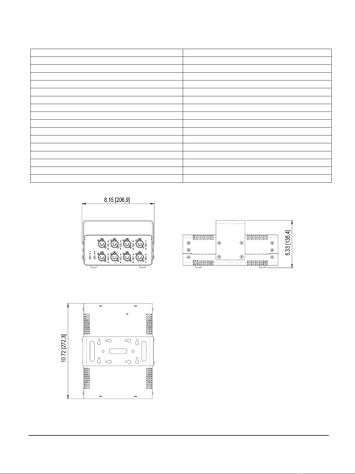
TECHNICAL SPECIFICATIONS
Part Number
PPDDS285RP (RDM) / PPDDS285P (DMX only)
DMX Inputs
2 XLR5 Male
DMX Outputs
8 Isolated + 2 Thru XLR5 Female
DMX Signal
DMX-512A
RDM
Yes, individual defeat for each input.
Additional Features
DMX Termination switch for each input
Signal Delay
Regeneration mode: 2μsec
In/Out/Out Isolation
Optical to 1000V
Power
100-240 VAC, 50-60 Hz (consumption 10W)
Mains Connector
Neutrik™ PowerCon NAC3MPA
Fuse
1A, 250V
Cooling
Convection
Operating Temperature
-4º to +104º F (-20º to +40º C)
Width
8.15 in / 206.9 mm
Depth
10.72 in / 272.3 mm
Height
5.33 in / 135.4 mm
Weight
TBD
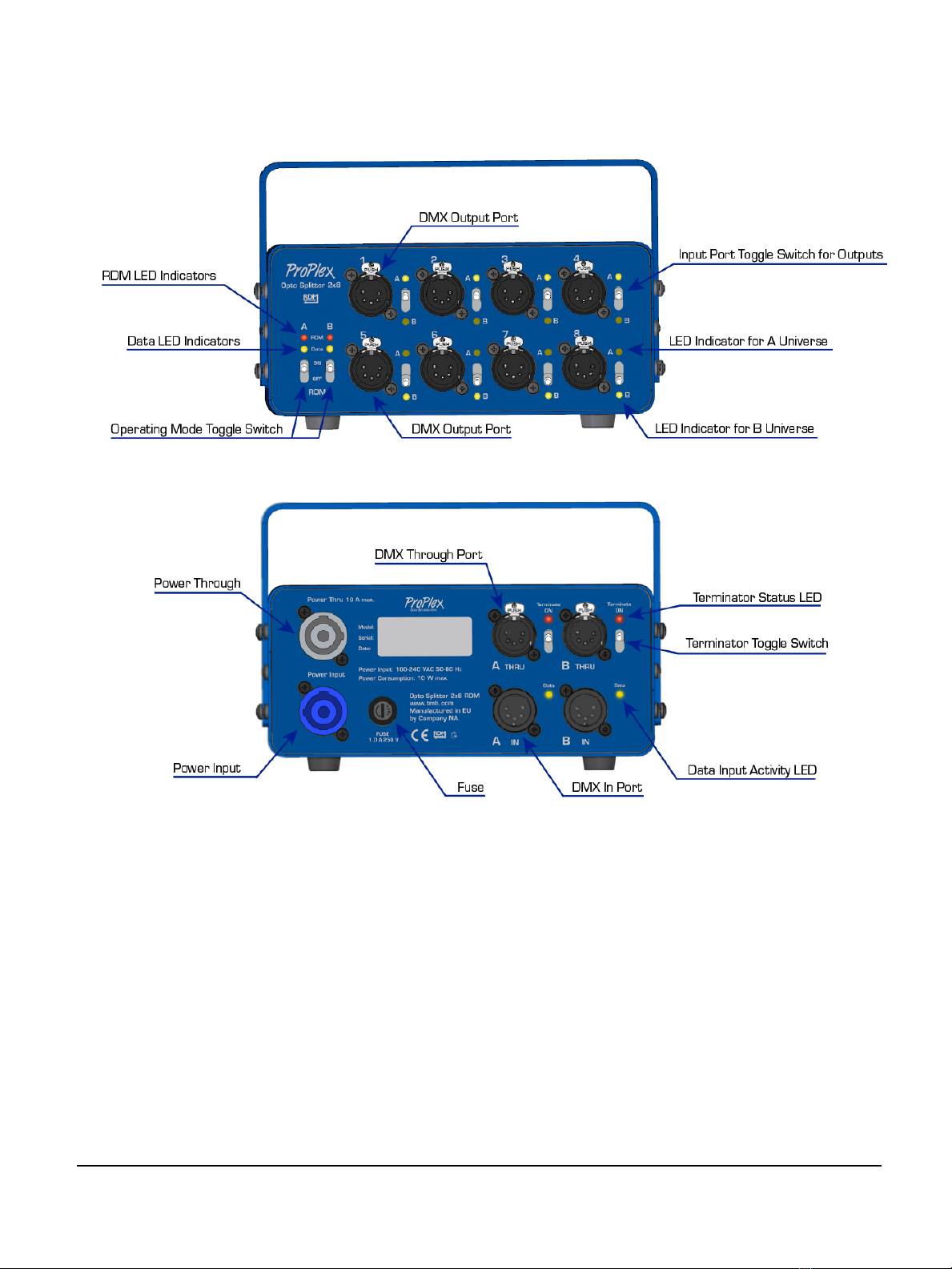
PANELS – FRONT AND BACK

RDM / DMX SERIAL LINK
1.
Connect the male 5-pin connector of the DMX cable to the female output 5-pin connector of the lighting
console.
2.
Connect the end of the cable coming from the lighting console which will have a female 5-pin
connector to the input connector of the DMX Splitter consisting of a male 5-pinconnector.
3.
Connect the output as stated above to the input of the following fixture and so on.
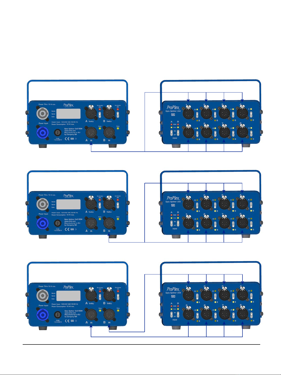
INPUT / OUTPUT CONNECTIONS
DMX splitter outputs can be manually switched to each of the two inputs. Following are a few examples.
Example 1: RDM/DMX Splitter input /output connection scheme 8+0: One of the DMX inputs is connected
to all of DMX outputs, but a second DMX input is not used, i.e. not connect to any of the DMX outputs.
Using Input A:
Using Input B:
Additional possibilities abound: e.g. 1+7; 2+6; 3+5; 4+4 etc.

OPERATING MODES (RDM)
The Opto-Splitter 2x8 PortableMount RDM has two modes: DMX, and DMX with RDM. Modes can be
switched using the toggle switch located on the front panel.
.
Switch is set to DMX Switch is set to DMX with RDM
ASSIGNING INPUTS TO OUTPUTS
Devices outputs can be connected to one of two inputs using the switches located to the right of each
output connector.
connected to
DMX input (A)
connected to
DMX input (B)

LED INDICATORS
FRONT PANEL LED INDICATORS
DATA – DMX input signal LED indicators are located on left side of the front panel and indicate whether the
DMX signal is received at the input. DMX input signal LED indicators have two modes:
•
Off: DMX signal is not present
•
Blinking: DMX signal is present
.
RDM – RDM signal processing mode LED indicator has two modes:
•
Off: RDM mode is turned off and splitter works in DMX-only mode
•
On: RDM mode is activated (Opto-Splitter passes RDM signal)
Note: Ensure all devices support RDM. Some DMX receiving chips are not able to process an RDM signal,
causing the device to behave erratically. If a problem occurs contact your device manufacturer.
RDM UNIVERSE INDICATORS
A Universe – LED indicators are located at each of the DMX splitter outputs, indicating whether the output is
connected to the DMX input A. The LED indicators have two states:
•
Off: The DMX signal output is not connected to input A
•
Blinking: The DMX signal output is connected to input A
B Universe – LED indicators are located at each of the DMX Splitter outputs, indicating whether the output
is connected to the DMX input B. The LED indicators have two states:
•
Off: The DMX signal output is not connected to input B
•
Blinking: The DMX signal output is connected to input B
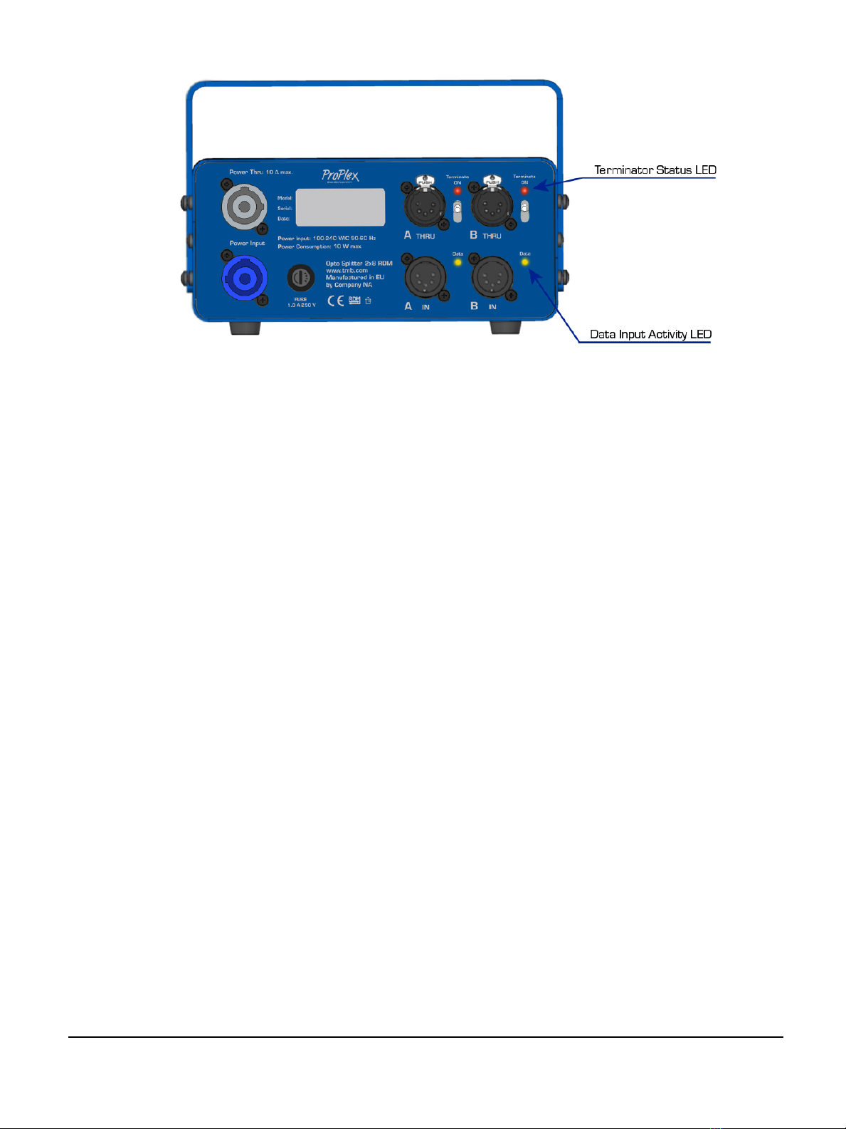
REAR PANEL LED INDICATORS
Terminator – The Terminator LED indicators signal whether the built-in DMX terminator is switched on or
off. There are two positions:
•
On: Terminator is activated.
•
Off: Terminator is deactivated.
Activate the DMX terminator if you want to stop data reflections.
Data – The DMX input signal LED indicates whether the DMX signal is received at the input. DMX input
signal LED indicators have two modes:
•
Off: DMX signal is not present
•
Blinking: DMX signal is present.
MOUNTING/RIGGING – PROPLEX ENCLOSURES
Rigging – Always consult a certified rigging specialist before suspending any device
overhead.
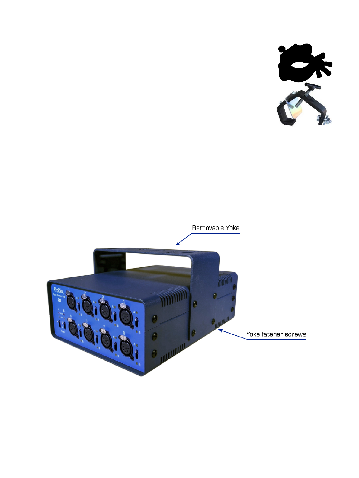
Use ProBurger®couplers or equivalent C- or O-type clamps for attaching to truss. After
establishing the desired position, tighten all appropriate bolts.
•
Always use safety cables!
•
When selecting installation location, consider routine maintenance.
•
Never mount Mini enclosure where it will be exposed to moisture, highhumidity,
extreme temperatures, or restricted ventilation.
RackMount Kit
ProPlex RackMount Kits are designed to allow easy rack mounting of ProPlex PortableMount units.
ProPlex PortableMount enclosures include a yoke for truss mounting. Before attaching RackMount Kit, remove the
yoke by unscrewing four Phillips-head (crosshead) screws which attach the yoke to the chassis.
Important: Be sure to reinsert the yoke screws into the unit after yoke has been removed.
ProPlex RackMount Kits are available for both Single- or Dual-unit mounting configurations. The 2U
RackMount Kit Single is comprised of two rack ears, one long and one short. The Dual has two short rack
ears + two dual joiners for front and rear of the units.
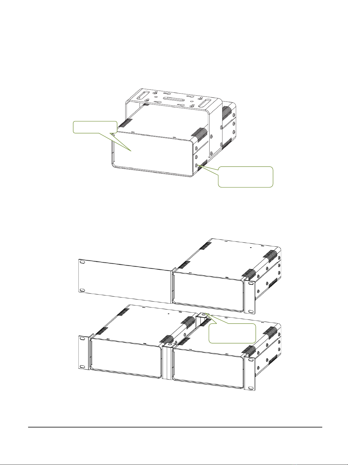
To fasten the rack ears to the ProPlex PortableMount chassis, remove the three chassis screws on each side
that align with the rack ear mounting holes at the front of the chassis. Then use the same screws to securely
fasten the ears to the chassis, per below illustrations. The short and long ears can be mounted to either side
of the chassis.
The drawing below depicts the 2U Large Single (top) and Dual (bottom) RackMount Kits. Note the Dual
version requires TWO center Dual Joiners (included in the Kit), attached at the front and rear of the units,
enhancing stability in the rack.
When ordering ProPlex RackMount Kit, Single or Dual, be sure and specify “Large” for the Opto-Splitter
2x8 PortableMount.
Important: Large Dual RackMount Kits are specified only for ProPlex PortableMount Devices (Opto-
Splitter 2x8 or IQ Two 66 2x). Only Large Single RackMount Kits are specified for PortableMount ProPlex
Drives (FloppyDrive, IMS Universe Drive, and Mozart Drive).
Front of unit
Rack ear screws
(3x ea. side)
Dual Joiners
(front and rear)
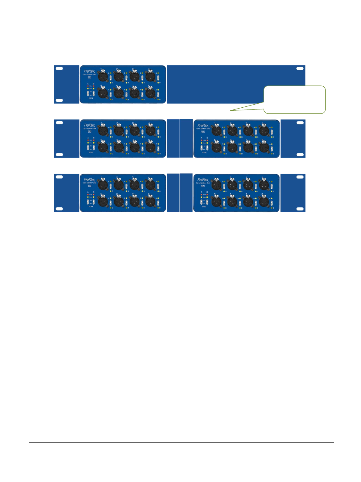
When installing multiple units, they can be mounted on alternating sides of the rack, side by side, or
underneath one another. When rack mounting ProPlex Opto-Splitter 2x8 PortableMount, ensure adequate
airflow when mounting one above the other, whether in Single or Dual Mounting configurations.
Allow minimum ½ U
rack space between
assemblies

LIMITED WARRANTY
ProPlex Data Distribution Devices are warranted by TMB against defective materials or workmanship for a
period of two (2) years from the date of original sale by TMB.
TMB’s warranty shall be restricted to the repair or replacement of any part that proves to be defective and for
which a claim is submitted to TMB before the expiration of the applicable warranty periods.
This Limited Warranty is void if the defects of the Product are the result of:
•
Opening the casing, repair, or adjustment by anyone other than TMB or persons specifically authorized
by TMB
•
Accident, physical abuse, mishandling, or misapplication of the product.
•
Damage due to lightning, earthquake, flood, terrorism, war, or act of God.
TMB will not assume responsibility for any labor expended, or materials used, to replace and/or repair the
Product without TMB’s prior written authorization. Any repair of the Product in the field, and any associated
labor charges, must be authorized in advance by TMB. Freight costs on warranty repairs are split 50/50:
Customer pays to ship defective product to TMB; TMB pays to ship repaired product, ground freight, back to
Customer.
This warranty does not cover consequential damages or costs of any kind.
A Return Merchandise Authorization (RMA) Number must be obtained from TMB prior to return of any
defective merchandise for warranty or non-warranty repair. For all repairs please contact TMB Tech Support
Repair using the contact information below or email TechSupportRepairNA@tmb.com.
US UK
527 Park Ave. 21 Armstrong Way
San Fernando, CA 91340 Southall, UB2 4SD England
Tel: +1 818.899.8818 Tel: +44 (0)20.8574.9700
Fax: +1 818.899.8813 Fax: +44 (0)20.8574.9701
tmb-inf[email protected] tmb-[email protected]
www.tmb.com www.tmb.com
RETURN PROCEDURE
Please send returned merchandise prepaid and in the original packing. Freight call tags will not be issued
for shipping the product to TMB, but TMB will pay the freight for return to the customer. Clearly label
package with a Return Merchandise Authorization Number (RMA #). Products returned without an RMA #
will delay service. Please contact TMB and request an RMA # prior to shipping the unit. Be prepared to
provide the model number, serial number, and a brief description of the cause for the return. Be sure to
properly pack the unit; any shipping damage resulting from inadequate packaging is the customer’s
responsibility. TMB reserves the right to use its own discretion to repair or replace product(s). Proper UPS
packing or double-boxing will better ensure product integrity when shipped.
Note: If you are given an RMA #, please include the following information on a piece of paper inside
the box:
1)
Your name
2)
Your address
3)
Your phone number
4)
The RMA #
5)
A brief description of the symptoms
This manual suits for next models
1
Table of contents
Other ProPlex Cables And Connectors manuals


