manuals.online logo
Brands
  1. Home
  2. •
  3. Brands
  4. •
  5. Proscend
  6. •
  7. Switch
  8. •
  9. Proscend 708EPI-DC User manual

Proscend 708EPI-DC User manual

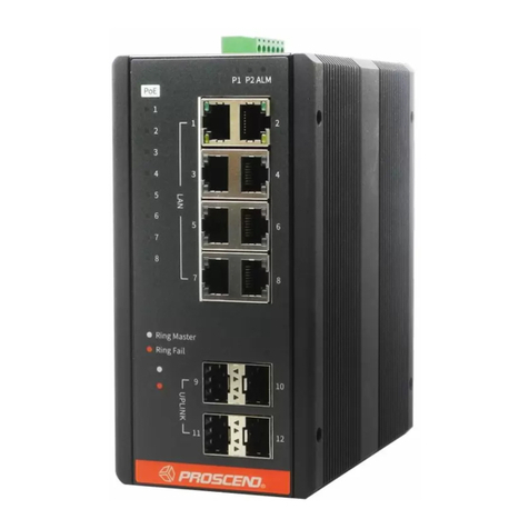
708EPI-DC 8-Port PoE Long Reach
Switch / Extender
Quick Installation Guide Version: 1.00
The 708EPI-DC PoE Switch / Extender features 8 pairs of Long Reach
Ethernet connections in cooperation with the 101EPI. Each pair carries
Ethernet traffic and power over an Ethernet cable up to 800 meters. The
708EPI-DC is designed to locate at network side where the 101EPI is
located at the remote side.
Overview
LED Indicators
Each LED indicator on the front panel is described in the following table.
LINE Port Pin Assignment
▪The power input interface is the 2-pin terminal block (+, -) on the front
panel and is provided the power input voltage 55 ~ 57 VDC/5A from the
power supply.
▪Insert the positive and negative wires into V+ and V- contact on the
terminal block and tighten the wire-clamp screws to prevent the wires
from being loosened.
To prevent the effects of noise from electromagnetic interference (EMI), run
the ground connection from the ground screw to the grounding surface
before connecting the devices.
Connecting the Power Supply
Ground Connection
Reset button allows you to reboot the unit or restore to factory default
setting.
Reset Button
The PoE pinouts of the LINE interfaces are as below when 8 wires are
connected.
Description
V+
V+
V-
V+
Pin
1
2
3
4
PoE Pinouts
Description
V+
V-
V-
V-
Pin
5
6
7
8
The PoE pinouts of the LINE interfaces are as below when 4 wires are
connected.
Description
V+
V+
V-
Not used
Pin
1
2
3
4
PoE Pinouts
Description
Not used
V-
Not used
Not used
Pin
5
6
7
8
Description
TX+
TX-
RX+
Not used
Not used
RX-
Not used
Not used
Description
RX+
RX-
TX+
Not used
Not used
TX-
Not used
Not used
Pin
1
2
3
4
5
6
7
8
Pin
1
2
3
4
5
6
7
8
MDI Port Pinouts MDI-X Port Pinouts
Reboot
Restore to factory default setting
Press the button for 1 second
Press the button for more than 5 seconds
Function Operation
The LINE interfaces of the 708EPI-DC are standard 8-pin
RJ45 connectors. The following tables display the pinouts.
1 8
8-pin RJ45
Color Description
Device Power On.
Device Power Off.
System is working.
System is off.
Device Error.
Powered Device Connected.
Powered Device Disconnected.
1000Mbps UPLINK LINK UP.
1000Mbps UPLINK LINK DOWN.
1000Mbps Data Transmitting.
100/10Mbps UPLINK LINK UP.
100/10Mbps UPLINK LINK DOWN.
100/10Mbps Data Transmitting.
100Mbps LINE LINK UP.
LINE LINK DOWN.
100Mbps Data Transmitting.
10Mbps LINE LINK UP.
LINE LINK DOWN.
10Mbps Data Transmitting.
LED LED
On
Off
On
Off
Blinking
On
Off
On
Off
Blinking
On
Off
Blinking
On
Off
Blinking
On
Off
Blinking
PWR
SYS
PoE1~8
UPLINK
LINE 1~8
Green
Green
Green
Green
Green
Yellow
Yellow
- 1 -
Proscend Communications Inc. All rights reserved. www.proscend.com
(1) Access the Web Configurator via UPLINK port or LINE ports.
STEP 1: Enter the default IP address 192.168.1.1 as URL in your web
browser.
STEP 2: Please enter the default username root and the default
password 2wsx#EDC.
STEP 3: Click Login button.
(2) Change the default password.
Go to User setting and reset your new password and then click Apply
button.
NOTE: The default password should be changed after configuration. Please avoid using easy to
guess passwords (e.g., root, 1234...).
DIN-rail Mounting
NOTE
󱾁Please scan below QR Code to download online resources.
Download Link: https://www.proscend.com/en/product/708E.html
708EPI-DC
ATTENTION: Safety Warning
󱾁Disconnect all power from devices before attempting installation.
󱾁This device is intended for installation only in restricted access locations as defined where both
these conditions apply:
・Access is through the use of a lock or tool and key, or other means of security, and is controlled
by the authority responsible for the location.
・Access can only be gained by service persons or by users who have been instructed about the
reasons for the restrictions applied to the location and about any precautions that shall be
taken.
󱾁All electric installations must be carried out in accordance with local and national regulations.
󱾁Do not work on the system, connect or disconnect cables during periods of lightning activity.
󱾁The equipment must be connected to earth.
󱾁Shield of RJ45 cables has to be connected to the same earth potential as the equipment.
󱾁Please remove the ground connection lastly if you need to remove the device after installation.
󱾁If the LINE interface is used for the connection between two buildings, all necessary protective
measures must be ensured externally.
󱾁This equipment relies on the building’s installation for short-circuit (overcurrent) protection. Ensure
that a fuse or circuit breaker no larger than 5A is used.
Wall Mounting
Setup
STEP 1: Use the screws to install the DIN-rail kit to attach at the rear side
of the device.
NOTE: Three screw types are flat head M3 x 4 mm.
STEP 1: At the bottom side of the device, use two screws to install each
bracket.
NOTE: Each screw type is flat head M3 x 4 mm.
STEP 2: Use the screws to attach the bracket of the device for wall
mounting.
NOTE: These screws are not included in the package. The head of each screw is less
than 7 mm in diameter, the shaft is less than 3 mm in diameter, and the length is less
than 10 mm in diameter.
STEP 2: Hook the unit onto the DIN-rail.
STEP 3: Push the bottom of the unit towards the DIN-rail until it locks in
place.
- 2 -
Proscend Communications Inc. All rights reserved. www.proscend.com
P/N:604040000070


This manual suits for next models

1

Other Proscend Switch manuals

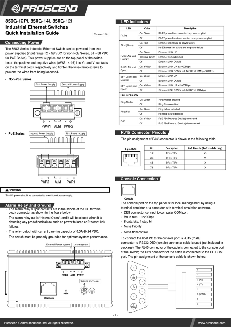
Proscend 850G Series User manual

Proscend

Proscend 850G Series User manual

Proscend 850G-14I User manual

Proscend

Proscend 850G-14I User manual

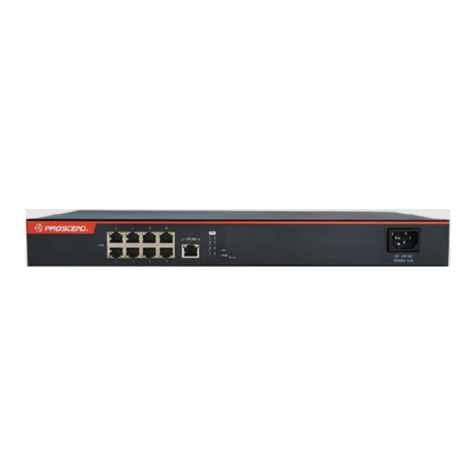
Proscend 708EP-AC User manual

Proscend

Proscend 708EP-AC User manual

Popular Switch manuals by other brands

Cisco HWIC-4ESW - EtherSwitch HWIC Switch user manual

Cisco

Cisco HWIC-4ESW - EtherSwitch HWIC Switch user manual

Potter PS100-2 manual

Potter

Potter PS100-2 manual

Linksys NMH300 - Media Hub Home Entertainment... Quick installation guide

Linksys

Linksys NMH300 - Media Hub Home Entertainment... Quick installation guide

Cisco 7008P - SFS InfiniBand Server Switch Regulatory compliance and safety information

Cisco

Cisco 7008P - SFS InfiniBand Server Switch Regulatory compliance and safety information

Radware OnDemand Switch 3 XL installation instructions

Radware

Radware OnDemand Switch 3 XL installation instructions

Hubbell Type AR Specification sheet

Hubbell

Hubbell Type AR Specification sheet

HP 445860-B21 - 10Gb Ethernet BL-c Switch reference guide

HP

HP 445860-B21 - 10Gb Ethernet BL-c Switch reference guide

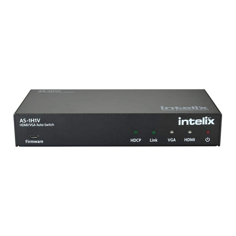
Intelix AS-1H1V Installation and operation guide

Intelix

Intelix AS-1H1V Installation and operation guide

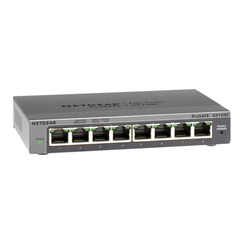
NETGEAR ProSAFE GS108Ev3 installation guide

NETGEAR

NETGEAR ProSAFE GS108Ev3 installation guide

MuxLab 500533 user manual

MuxLab

MuxLab 500533 user manual

KSB M 1 Installation & operating manual

KSB

KSB M 1 Installation & operating manual

Spamel OP1 quick start guide

Spamel

Spamel OP1 quick start guide

HP 6125XLG Command reference

HP

HP 6125XLG Command reference

Larson Electronics EPS-10HP-3PST Operation manual

Larson Electronics

Larson Electronics EPS-10HP-3PST Operation manual

Gefen EXT-DVIKVM-241DL user manual

Gefen

Gefen EXT-DVIKVM-241DL user manual

Optical Systems Design OSD2790SFP quick start guide

Optical Systems Design

Optical Systems Design OSD2790SFP quick start guide

TRENDnet TEG-240WS Quick installation guide

TRENDnet

TRENDnet TEG-240WS Quick installation guide

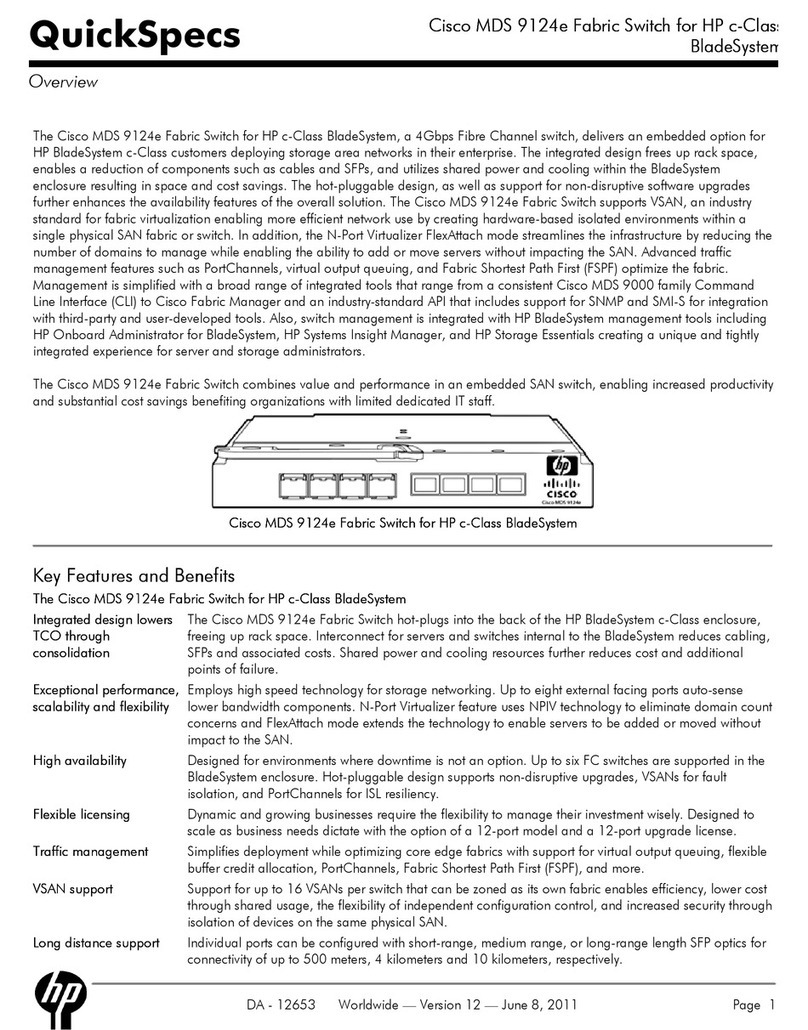
Cisco MDS 9124e specification

Cisco

Cisco MDS 9124e specification

manuals.online logo
manuals.online logoBrands
  • About & Mission
  • Contact us
  • Privacy Policy
  • Terms and Conditions

Copyright 2025 Manuals.Online. All Rights Reserved.