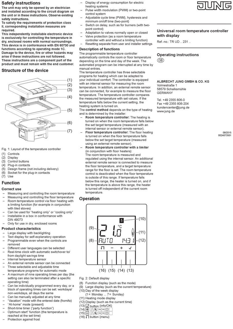
Prosensor N480D User manual

MICROPROCESSOR BASED TEMPERATURE CONTROLLER
N480D
OPERATING MANUAL
1. SAFETY SUMMARY
The symbols below are used on the equipment and throu hout this document to draw the user’s attention to
important operational and safety information.
CAUTION or WARNIN :
Read complete instructions prior to installation
and operation of the unit.
CAUTION or WARNIN :
Electrical Shock Hazard
All safety related instructions that appear in the manual must be observed to ensure personal safety and to
prevent dama e to either the instrument or the system. If the instrument is used in a manner not specified by
the manufacturer, the protection provided by the equipment may be impaired.
2. INSTALLATION
The controller should be installed in a panel cut out as specified in item 2. First remove the mountin clamp
and insert the controller into the panel cut out. Place the unit into the panel cut-out and slide the mountin
clamps from the rear to a firm rip at the panel.
The internal circuitry can be fully removed from the housin without disconnectin any wirin . Grab firmly the
front panel and pull out the circuitry from the housin .
2.1 ELECTRICAL CONNECTIONS
All electrical connections are made to the screw terminals at the rear of the controller. They accept wire sizes
from 0.5 to 1.5 mm2 (16 to 22 AWG). The terminals should be ti htened to a torque of 0.4 Nm (3.5 lb in).
The installation must include a power isolatin switch or circuit breaker that disconnects all current carryin
conductors. The device should be mounted close to the controller, within easy reach of the operator and
marked as the disconnectin device for the instrument.
Fi ure 1 shows the electrical terminals of the controller.
Fi ure 1 - Back panel terminals
3. SPECIFICATIONS
•Dimensions: 48 x 48 x 110 mm (1/16 DIN). Panel cut-out: 45,5 x 45,5 mm. Wei ht: 160 (max);
•Power: 100 to 240 Vac/dc (±10 %), 50/60 Hz or 24 Vdc/ac (±10 %); Max. Consumption: 9 VA;
•Pt100: α= 385. 3-wire connection. Excitation current: 0.170 mA;
•Accuracy: 0.2 % of full scale for Pt100 and 0.25 % of full scale ±1 °C for T/C
•Thermocouple input impedance: 10 MΩ
•A/D converter resolution: 15000 steps
•Samplin rate: 10 measurements per second
•Environmental conditions: 5 to 50 °C; Relative humidity (maximum): 80 % up to 30 ºC. For temperatures
above 30 ºC, decrease 3 % per ºC. Installation cate ory II. Pollution de ree 2. Altitude < 2000 m.
•Front Panel: Polycarbonate UL94 V-2; Back Panel: ABS + PC UL94 V-0
•EMC: EN 61326-1:1997 and EN 61326-1/A1:1998
•SAFETY: EN61010-1:1993 and EN61010-1/A2:1995
3.1 TEMPERATURE SENSOR INPUT
Thermocouples are connected to terminals 10 and 11 with positive in terminal 11. Pt100 sensors are
connected to terminals 10, 11 and 12, as indicated in fi ure 1. For full compensation of cable resistance only
cables with equal wire electrical resistance should be used. Table 1 shows the sensor types accepted and
their respective codes.
TIPO CÓDI O FAIXA
J 0
00
0
-50 to 760 °C (-58 to 1400 °F)
K 1
11
1
-90 to 1370 °C (-130 to 2498 °F)
S 2
22
2
0 to 1760 °C (32 to 3200 °F)
Pt100 (Resolution 0,1°C) 3
33
3
-199.9 to 530.0 °C (-199.9 to 986.0 °F)
Pt100 (Resolution 1°C) 4
44
4
-200 to 530 °C (-328 to 986 °F)
T 5
55
5
-100 to 400 °C (-148 to 752 °F)
E 6
66
6
-30 to 720 °C (-22 to 1328 °F)
N 7
77
7
-90 to 1300 °C (-130 to 2372 °F)
R 8
88
8
0 to 1760 °C (32 to 3200 °F)
Table 1 - Sensor types, codes and ran es
3.2 POWER
Mains power is connected to terminals 1 and 2. Check the upper side of the housin for proper power
indication.
3.3 CONTROL AND ALARM OUTPUTS
Up to 4 outputs can be confi ured for control or alarm. The available outputs are identified on the rear panel
as OUTA, OUTB, OUTC or OUTD. Electrical characteristics of each output are:
OUTA: SPST Relay, 1,5 A / 250 Vac (3 A / 30 Vdc); Resistive load; 100 k cycles;
OUTB: Volta e Pulse, 5 Vdc / 20 mA;
OUTC: SPST Relay, 1,5 A / 250 Vac (3 A / 30 Vdc); Resistive load; 100 k cycles;
OUTD: SPDT Relay, 3 A / 250 Vac (3 A / 30 Vdc); Resistive load; 6 k cycles;
or 4-20 mA output. With 80 count resolution, precision: 0,25 mA, maximum load: 500 Ohms.
The output function is defined on controller confi uration, parameters IO A
IO AIO A
IO A, IO B
IO BIO B
IO B, IO (
IO (IO (
IO ( and IO d.
IO d.IO d.
IO d.
Control Output is used to control the process variable usin PID al orithm. More than one output can be
selected as control output. When OUTD is confi ured as Analog Control Output, all other outputs selected
as Control Output will not operate.
Control Outputs are turned off when a sensor error is detected (display “Erro
ErroErro
Erro”).
Alarm Outputs are used to si nal abnormal PV values, sensor error or end of pro ram. The alarm function
must be selected for each alarm output. (Refer to chapter 9).
4. CONFI URATION AND OPERATION
Prior to first operation the controller should be fully confi ured. The user must set basic parameters as
temperature type (“TYPE
TYPETYPE
TYPE”), the desired control set point (“ SP
SPSP
SP “), the alarms set points (“SPA1
SPA1SPA1
SPA1” and
“SPA2
SPA2SPA2
SPA2”), etc.
4.1 PARAMETERS FLOW CHART
The pro rammin parameters are or anized in 4 different sets or levels
Operation level / Alarms and tuning level / Configuration level / Calibration level
At power up the controller displays a prompt at the Operation Level and remains in this level while under
normal operation.
The other levels are only accessed when a chan e of parameters is necessary (except for Set Point
chan e). To reach these other parameters the user must keep the PRO Key (
P
) pressed for about
three seconds. After this time the controller will show the first parameter of the next level. By keepin the
P
key pressed for another 3 seconds the next level will be accessed.
Release the
P
key when the desired level is reached. Press once the
P
to o to the next prompt in the
same level. When a parameter is shown the display will alternate its name and value. The value can then be
chan ed by pressin the or key.
After the last parameter in one level is reached the controller returns to operation level and the display will
indicate the measured temperature.
The display will also o back to the measured temperature whenever the display is inactive for 20 seconds
or more. When a parameter value is chan ed via keyboard the controller will only accept the new value after
the user presses the
P
key to o to next prompt or if the keyboard is left inactive for 20 seconds.
4.2 PROGRAM SECURITY
To avoid tamperin , parameter “Prot
ProtProt
Prot” and a hardware jumper can be used to disable access to
pro rammin parameters.
With the jumper in the OFF position, all pro ram levels are unprotected. The “Prot
ProtProt
Prot” parameter can only be
chan ed with the jumper in the OFF position.
With the jumper in the ON position or removed, the protection level is defined by the current value of the
“Prot
ProtProt
Prot” parameter:
0
00
0 No protection. All parameters can be accessed;
1
11
1 No access to the calibration level;
2
22
2 No access to calibration and confi uration levels;
3
33
3 No access to calibration, confi uration and tunin and alarms levels;
4
44
4 No access to calibration, confi uration, tunin and alarms and operation (except SP) levels;
5
55
5 Fully blocked.
OFF
ON
Fi ure 2 – Protection Disabled Fi ure 3 – Protection Enabled
4.3 OPERATION LEVEL
TEMPERATURE
INDICATION
END
SP
TEMPERATURE measured by the sensor. At power up, the upper display shows the
process temperature value. It also shows the messa es described in chapter 5 of this
manual. The lower displays shows the set point value which is the temperature value
desired for the process.
rAte
TEMPERATURE RATE OF RISE: The user defines the rate of temperature rise from the
startin temperature to the value set in “ SP
SPSP
SP ”. Rate is defined in °C / minute.
T Sp TIME FOR SOAK: Time in minutes which the temperature will remain at the selected “
SP
SPSP
SP “. Refer to item 4.
Rvn
run
RUN: At this prompt the user sets the control output and alarms to active or to inactive.
0
00
0 - inactive outputs; 1
11
1 - active outputs;
4.4 TUNING AND ALARMS LEVEL
Atvn AUTO-TUNE: Activates the auto-tunin of PID parameters.
0
00
0 - Auto-tune is off; 1
11
1 - Auto-tune is on;
Pb
Proportional band
PROPORTIONAL BAND: percenta e of maximum input span.
When set to zero (0), control action is ON/OFF.
Ir
inte ral rate
INTE RAL RATE: Inte ral time constant in repetitions per minute (Reset). This
constant is not used when controller is set to ON/OFF action (Pb=0).
t
derivative time
DERIVATIVE TIME: Derivative time constant in seconds. This constant is not used
when controller is set to ON/OFF action (Pb=0).
(t
Cycle time
CYCLE TIME: Pulse Width Modulation (PWM) period in seconds. This term is not
used when controller is set to ON/OFF action (Pb=0).
KySt
HYSteresis
CONTROL HYSTERESIS: Is the hysteresis for ON/OFF control (set in temperature
units). This parameter is only used when the controller is in ON/OFF mode (Pb=0).
A1SP
A2SP
SP Alarm
SETPOINT for Alarm 1/2: Tripin point for alarm 1/2.

4.5 CONFIGURATION LEVEL
Type
tYPE
INPUT TYPE: Selects the input sensor type to be connected to the controller. This is
the first parameter to be set.
0
00
0 - Thermocouple type J; 5
55
5 - Thermocouple type T;
1
11
1 - Thermocouple type K; 6
66
6 - Thermocouple type E;
2
22
2 – Thermocouple type S; 7
77
7 - Thermocouple type N;
3
33
3 - Pt100 with 0,1° resolution; 8
88
8 - Thermocouple type R;
4
44
4 - Pt100 with 1° resolution;
Vnit
unit
TEMPERATURE UNIT: Selects display indication for de rees Celsius or Fahrenheit.
0
00
0 - de rees Celsius ( °C ); 1
11
1 - de rees Fahrenheit ( °F );
A(t
ACtion
CONTROL ACTION: 0
00
0 - reverse action. Generally used for heatin .
1
11
1 - direct action. Generally used for coolin .
Io A
Out A
OUTA FUNCTION: 0
00
0 - OUTA is control output.
1
11
1 - OUTA is Alarm 1 output.
2
22
2 - OUTA is Alarm 2 output.
Io b
Out B
OUTB FUNCTION: 0
00
0 - OUTB is control output.
1
11
1 - OUTB is Alarm 1 output.
2
22
2 - OUTB is Alarm 2 output.
Io (
Out C
OUTC FUNCTION: 0
00
0 - OUTC is control output.
1
11
1 - OUTC is Alarm 1 output.
2
22
2 - OUTC is Alarm 2 output.
Io d
Out D
OUTD FUNCTION: 0
00
0 - OUTD is control output.
1
11
1 - OUTD is Alarm 1 output.
2
22
2 - OUTD is Alarm 2 output.
3
33
3 - OUTD is Analo Control Output (4-20mA).
spll
SP Low Limit
SET POINT LOW LIMIT: sets the lower ran e for SV.
spKl
SP Hi h Limit
SET POINT HI H LIMIT: Sets the upper ran e for SV.
0ffs
OFF Set
SENSOR OFFSET: Offset value to be added to the PV to compensate sensor error.
Default value: zero.
A1fv
A2fv
Alarm 1 Function
FUNCTION OF ALARM 1/2
: Refer to table 2 for function description and respective
codes to set at this prompt.
Aiky
A2ky
Alarm HYsteresis
ALARM 1 AND ALARM 2 HYSTERESIS: Defines the differential ran e between the
PV value at which the alarm is turned on and the value at which it is turned off.
Prot
Protection
PRO RAM SECURITY: Defines the level of parameters protection from tamperin .
Refer the chapter 4.2.
4.6 CALIBRATION LEVEL
These parameters are used to calibrate the temperature measurement and should only be dealt with by
experienced and well equipped personnel.
Inl(
Input Low Calibration
SENSOR OFFSET CALIBRATION. Sets the temperature sensor low calibration
(offset). The display shows only the corrected temperature and not the offset
added. A si nal simulator should be used to inject a low value si nal to properly
adjust the offset.
InK(
Input Hi h Calibration
INPUT HI H CALIBRATION. Sets the sensor input circuit ain or hi h
calibration. A si nal simulator should be used to inject a hi h value si nal to
properly adjust the offset.
(j L
Cold Junction Low
Calibration
COLD JUNCTION OFFSET CALIBRATION: Sets the cold junction offset
calibration. A ood thermometer or a temperature simulator should be used to
properly adjust this parameter.
Ovl(
output Low Calibration
OFFSET CALIBRATION OF ANALO OUTPUT: Offset (zero) calibration of the
analo control output (4-20 mA).
OvK(
output Hi h Calibration
AIN CALIBRATION OF ANALO OUTPUT: Gain (span) calibration of the
analo control output (4-20 mA).
5. RAMP TO SOAK FUNCTION CHARACTERISTICS
This function makes the process temperature rise radually from the startin point (present PV) to the
temperature value set in “ SP
SPSP
SP “ (Ramp). The user defines the rate of rise in de rees per minute at the “rAtE
rAtErAtE
rAtE”
prompt. When SP is reached the temperature is leveled at this point for 1 to 9999 minutes as pro rammed at the
“ t SP
t SPt SP
t SP ” prompt. Settin 0 (zero) at “ t SP
t SPt SP
t SP ” defines an infinite len th soak profile.
Soak
Temperature
PV
Ramp
Time
SP
Fi ure 2 - Ramp to Soak Function
To disable the ramp function Set 0.0 at the “rAtE
rAtErAtE
rAtE” prompt. To disable the soak function set 1 at the “ t SP
t SPt SP
t SP
” prompt (thus makin a 1 minute soak) and the control output will o off in 1 minute. To restart control set 1
at the “ rvn
rvnrvn
rvn ” prompt.
After a power failure the controller will resume ramp to soak execution at the equivalent previous ramp point.
If the process temperature is the same as the SP (no temperature drop) the controller will repeat the soak
se ment.
6. PID AUTO TUNE
Durin auto tune the temperature is controlled in ON/OFF mode at the pro rammed Set Point (SV).
Dependin on the process characteristics lar e oscillations above and below SV may occur and auto tunin
may take several minutes to be concluded.
The recommended procedure is as follows:
•Pro ram a new SP close to the desired final temperature other than the present measured temperature.
•Enable the auto tune at the “Atvn
AtvnAtvn
Atvn” prompt by selectin 1.
•Set 1 at the “rvn
rvnrvn
rvn” prompt. The TUNE messa e will be si naled in the display.
Durin auto tune lar e oscillations will be induced around the set point. Make sure the process can accept
these oscillations. If auto tunin results are not satisfactory refer to table 3 for manual fine tunin procedure.
PARAMETER RESPONSE SOLUTION
Slow Response Decrease
Proportional
Band Lar e Oscillation Increase
Slow Response Increase
Inte ral
Rate Lar e Oscillation Decrease
Slow Response or Instability Decrease
Derivative
Time Lar e Oscillation Increase
Table 3 - Su estions for manual tunin of PID parameters
7. ALARM FUNCTIONS
Low and hi h alarms are used to si nal minimum and maximum temperature values as pro rammed in the
“SPA1
SPA1SPA1
SPA1” and “SPA2
SPA2SPA2
SPA2” prompts.
Differential alarms are used to indicate deviations from the desired set point (SP) temperature. These
deviations are pro rammed at the “SPA1
SPA1SPA1
SPA1” and “SPA2
SPA2SPA2
SPA2” prompts. Error alarm shows sensor defects or not
properly connected. Table 2 shows each alarm function operation with their respective code. Alarm 1 is used
as an example.
7.1 ALARM INITIAL BLOCKING
The initial blockin option inhibits the alarm from bein reco nized if an alarm condition is present when the
controller is first ener ized. The alarm will actuate only after the occurrence of a non alarm condition
followed by a new occurrence for the alarm.
TYPE CODE ACTION
LOW 0
00
0
SPA1
Alarm ON
Ligado
TEMPERATURE
HIGH 1
11
1
SPA1
Alarm ON TEMPERATURE
SPA1
SPA1SPA1
SPA1
Ne ative
SP + SPA1
SP
Alarm
ON
TEMPERATURE
LOW
differential 2
22
2
SPA1
SPA1SPA1
SPA1
Positive
SP + SPA1
SP
Alarm ON
TEMPERATURE
SPA1
SPA1SPA1
SPA1
Ne ative
SP + SPA1
SP
Alarm ON
TEMPERATURE
HIGH
differential 3
33
3
SPA1
SPA1SPA1
SPA1
Positive
SP + SPA1
SP
Alarm
ON
TEMPERATURE
SPA1
SPA1SPA1
SPA1
Ne ative
SP - SPA1
SP + SPA1
SP
Alarm ON TEMPERATURE
differential
or deviation 4
44
4
SPA1
SPA1SPA1
SPA1
Positive
SP + SPA1
SP - SPA1
SP
Alarm
ON
Alarm
ON TEMPERATURE
Input sensor
error or
heater
break
detection
5
55
5
Alarm is ON whenever:
•Temperature is below/above selected ran e;
•Thermocouple or Pt100 is broken;
•Pt100 is shorted; badly connected or wire impedance is too hi h;
•The heater resistance is broken
End of
Pro ram 6
66
6
Activated when the pro rammed soak time is run out. Refer to item 4 of this
manual.
7
77
7
Low limit alarm disabled at power-up
8
88
8
Hi h limit alarm disabled at power-up
9
99
9
Differential low limit alarm disabled at power-up
10
1010
10
Differential hi h limit alarm disabled at power-up
Alarm
Functions
With alarm
inhibition at
power-up
11
1111
11
Differential alarm disabled at power-up
Table 2 - Alarm functions and their identification codes
8. PROBLEMS WITH THE CONTROLLER
Connection and confi uration errors state for most of the problems in usin the controller. A final revision of
parameters will save time and further losses.
Error messa es are displayed to help the user to identify possible problems.
: Process temperature is below the selected sensor ran e.
: Process temperature is above the selected sensor ran e
: Controller or sensor error. Example: Broken thermocouple or Pt100, Pt100 badly
connected, short-circuited or hi h cable resistance.
5.1 GETTING THE INSTRUMENT SERIAL NUMBER
Upon power-on, the controller displays its firmware version for 3 seconds. The serial number is accessed
when the controller is powered while holdin the key pressed.
9. PRODUCT IDENTIFICATION
The label attached to the controller case identifies the model and the optional present in the product, as
described below:
MODEL: N480D – A – B, where:
A: Outputs: RP (OUT A = Relay, OUT B = Pulse)
RPR (OUT A = Relay, OUT B = Pulse, OUT D = Relay)
RRR (OUT A = Relay, OUT C = Relay, OUT D = Relay);
RAR (OUT A = Relay, OUT C = Relay, OUT D = 4-20 mA )
B. Volta e ratin : blank (100-240 Vac/dc) or 24V (24 Vac/dc);
Popular Temperature Controllers manuals by other brands
S+S Regeltechnik
S+S Regeltechnik Thermasreg RTR-S Series Operating Instructions, Mounting & Installation
Carrier
Carrier NSA-HH/CO2-R2-CP-C Additional Instructions for Installation and Operation
Honeywell
Honeywell C7772A Product data
HAOZEE
HAOZEE NW-HT user manual
Daikin
Daikin Altherma EHVZ08S18CB User reference guide

Eurotherm
Eurotherm 3116 user guide
