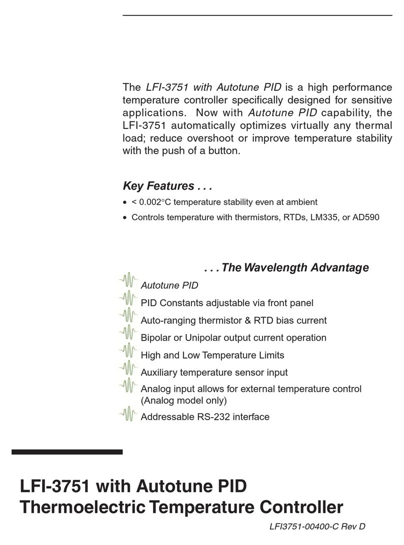
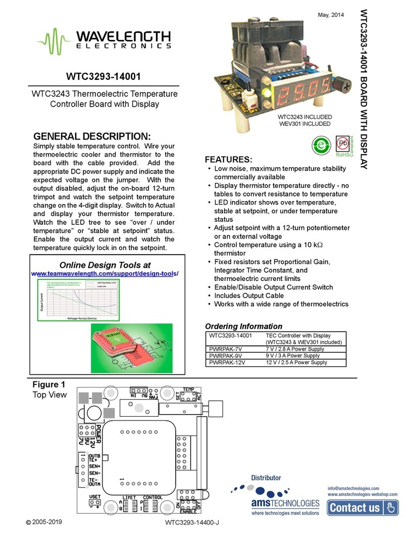
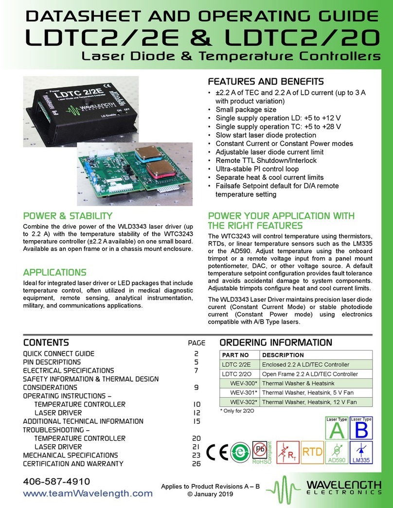
Wavelength Electronics LFI-3500 Series User manual

TM
LFI-3500 Series
Temperature Controllers
User’s Guide

2

3
LFI-3500 Series
Temperature Controller
User’s Guide
Publication number 92-130002D
© Copyright 1996, 1997, Wavelength Electronics, Inc.
P O Box 865, Bozeman, MT 59771
All Rights Reserved
Printed in U. S. A.

4
Thermoelectric Temperature Controllers
The 3500 series advanced design offers an unprecedented combination of features,
performance, and value. A variety of sensors including thermistors, IC sensors (AD590
and LM335), and RTDs are supported. A versatile I/O analog interface is provided at no
additional cost. Connect a standard 12 V fan to the 3500 series and cool your TE's
heatsink.
The fast PID control circuitry provides low noise, stable performance for even the most
stringent temperature control situations. With four proportional gains, two integral time
constants, and an optional derivative time constant, the PI/PID control loop can stabilize
virtually any load. The 3500 series utilizes Wavelength's "Smart Integrator" circuit to
reduce overshoot and improve settling time.
Extensive protection features are incorporated into the 3500 series to protect your
thermoelectric and temperature controlled device from damage. Easy to read LEDs
indicate temperature limit, open thermoelectric, and sensor open/short conditions.
Temperature and current limits are readily adjustable from front panel trimpots. For
additional safety, use the analog interface to disable an LFI-4500's laser diode driver
output if the temperature controller output is turned off for any reason.
Interlock any combination of LFI-3500 series temperature controllers or LFI-4500 series
laser diode drivers without additional hardware. Two or more modules mount into a 19"
rack with optional rack mount kits.
KEY FEATURES...
•Ultra stable temperature control (< 0.002 °C)
•Compatible with Thermistors, AD590, LM335, and RTDs
•Four models deliver 15, 22, 25, and 40 W
•Wide temperature control range from −60°C to > +150°C
•Easy to adjust operating temperature and current limit
•Linear, low noise, bipolar current source
...THE WAVELENGTH ADVANTAGE
Low cost, flexible instrument
Fast PID control with "Smart Integrator" overshoot suppression
Adjustable "LOW" or "HIGH" temperature limit protection
Auxiliary thermistor monitors heatsink or ambient temperature
Connect an external fan and cool your TE's heatsink
Display thermoelectric voltage and current
Interlocking enclosures for complete laser drive solutions
Comprehensive Analog Interface includes:
TE V, TE I, TEMP SET, and ACTUAL TEMP outputs
Remote output ON/OFF control
External control of operating temperature
"Open Drain" ON/OFF and error status outputs
Directly integrates with LFI-4500 series laser diode drivers
Booster signal can drive higher powered amplifiers
5
LFI 3500 Series Selection Guide
Model Description
LFI-3525 15 W, 2.5 Amp, 6 Volt, Temperature Controller
LFI-3526 22 W,2.5 Amp, 9 Volt, Temperature Controller
LFI-3550 25 W, 5.0 Amp, 5 Volt, Temperature Controller
LFI-3551 40 W, 5.0 Amp, 8 Volt, Temperature Controller
Each model includes: 9&15 pin D-sub receptacles with shielded covers and hardware, user guide,
and AC power cord.
Cable - Selection Guide
Model Description
CAT-204 Output cable, single connector (9 pin D-sub rec)
One end connectorized one end
unterminated
CAT-205 Output cable, double connector (9 pin D-sub rec's)
Both ends connectorized
All cables are 1 meter long.
Rack Mount Kits- Selection Guide
Model Description
RMK-502 Rack mount kit for two LFI modules
Includes two
5 1/4" panels
RMK-503 Rack mount kit for three LFI modules
Includes one
1" panel and one
5 1/4" panel
RMK-504 Rack mount kit for four LFI modules
Includes two
1" panels
All RMK kits include (4)- 1/4-20 screws. No additional hardware is required to
attach rack mount brackets to LFI modules.
Thermistor Selection Guide
MODEL R @ 25°°C10 µµA RANGE 100 µµA RANGE
TCS-602 2.252 kΩΩ −−60°°Cto −−12°°C−−33°°Cto +15°°C
TCS-605 5 kΩΩ −−55°°Cto −−2°°C−−20°°Cto +33°°C
TCS-610 10 kΩΩ −−45°°Cto +13°°C−−8°°Cto +50°°C
TCS-620 20 kΩΩ −−35°°Cto +28°°C+6°°Cto +69°°C
TCS-650 50 kΩΩ −−18°°Cto +49°°C+25°°Cto +92°°C
TCS-651 100 kΩΩ −−6°°Cto +67°°C+41°°Cto +114°°C

6
Default Configuration from the Factory
The following are the factory default settings.
Rear Panel:
CONFIGURATION SWITCH:
OFF
ON2 3 4 5 6 7 91 108
CONFIGURATION
Sensor setting: Thermistor, 100µA reference current
Loop Direction: NTC, for thermistors
PID Constants: P = 32, I = 1 second, D = OFF
Temperature Limit = HIGH
Front Panel:
LIMITS:
Temperature Limit: set at 7.72kΩ
(7.72kΩcorresponds to 30°C for a TCS-610 10kΩthermistor)
Current Limit: 500 mA for LFI-3525 & LFI-3526
1 Amp for LFI-3550 & LFI-3551

7
TABLE OF CONTENTS
Default Configuration from the Factory ___________ 6
Safety Summary ______________________________ 8
Front Panel At a Glance _______________________ 10
Rear Panel At a Glance _______________________ 12
Preparing the Temperature Controller for Use_____ 15
Operating Guidelines _________________________ 16
Operation with Thermistors __________________ 16
Operation with the AD590____________________ 18
Operation with the LM335____________________ 20
Operation with RTDs________________________ 22
Set the Thermoelectric Current Limit __________ 25
Set the Temperature Limit ___________________ 26
Further Information___________________________ 28
Configure the PID Constants _________________ 28
Practical PID Setups ________________________ 30
Error and Status Indicators __________________ 31
Analog Interface ___________________________ 32
General Specifications ______________________ 34
Electrical Specifications_____________________ 35
Mechanical Specifications ___________________ 36
Cable Accessories__________________________ 37
Warranty ___________________________________ 38

8
Safety Summary
Do not install substitute parts or perform any unauthorized modification to the
product. Return the product to Wavelength Electronics for service and repair
to ensure that safety features are maintained.
Do not use this product beyond its specifications.
SYMBOL DEFINITION OF SYMBOL
WARNING
Calls attention to a procedure, practice, or condition that could
possibly cause bodily injury or death.
ATTENTION
Ce symbole signale une procédure ou des conditions
dangereuses pouvant entraîner des blessures corporelles ou la
mort.
VORSICHT!
Nichtbeachtung der Hinweise können die körperliche
Unversehrtheit beeinträchtigen oder zum Tod führen.
NOTE! Calls attention to a procedure, practice, or condition that could
possibly cause damage to equipment or devices being
operated by this equipment.
CAUTION Risk of Electric Shock
ATTENTION Risque d’Electrocution
VORSICHT Hochspannung
Earth Ground Symbol
Chassis Ground Symbol
!

9
NOTE! Complete all operational steps in the order provided. Skipping
a step can result in damage to the device being controlled or
the Thermoelectric Module. Start with the section appropriate
to the type of sensor you are using
WARNING
For continued protection against fire, replace line fuse only with
fuse specified, type and rating.
ATTENTION
Pour une protection permanente contre les risques d’incendie,
ne remplacer les fusibles secteur que par des fusibles
conformes aux spécifications.
VORSICHT
Defekte Sicherungen sind nur durch die angegeben Typen und
mit den spezifizierten Werten zu ersetzen um die Sicherheit des
Gerätes zu gewährleisten.
CAUTION
RISK OF ELECTRICAL SHOCK. Do not power on this
instrument if the case is damaged or any of the covers or
panels are removed. NO USER SERVICEABLE PARTS
INSIDE.
ATTENTION
Risque d’Electrocution. Ne pas mettre sous tension cet
instrument si le boîtier est endommagé ou si les capots ou les
faces sont retirés. Aucun composant réparable par l’utilisateur.
VORSICHT
Hochspannung. Im Falle eines Gerätedefektes oder bei
geöffneter Verkleidung Netzstecker ziehen! Gerät kann und
braucht vom Anwender nicht gewartet werden.
CAUTION
POSSIBLE ELECTRICAL SHOCK OR FIRE HAZARD. Do not
expose the LFI Temperature Controller to rain or moisture. Do
not operate this instrument in the presence of flammable gases
or fumes.
ATTENTION
Risque d’électrocution ou d’incendie. Ne pas exposer
l’alimentation LFI à la pluie ou à l’humidité. Ne pas utiliser cet
instrument en présence de gaz inflammable ou de fumée.
VORSICHT
Brandgefahr und Gefahr eines elektrischen Schocks! Setzen
Sie das Gerät nicht dem Regen oder der Feuchtigkeit aus.
Schalten Sie das Gerät in der Gegenwart entflammbarer Gase
oder Dämpfe nicht ein!
!


11
Temp Limit LED: This LED lights red whenever the load temperature exceeds the
limit temperature set by the Temp Limit Trimpot. The output current is switched off
when this error occurs.
Temp Limit Trimpot: This adjusts the Temp Limit Setpoint.
Sensor Error LED: This LED lights red whenever the sensor voltage is either
greater than 5V or less than 0.2V. This refers only to the feedback sensor, not the
auxiliary sensor. This condition can occur if the impedance of the sensor is too
high or too low, or if the sensor is disconnected from the Output Connector. The
output current is automatically switched off when this error occurs.
Output Section:
Output Enable Button: This button enables and disables the thermoelectric
current source output. When the output is enabled, the current is determined by
the load conditions. If the output is disabled, the output current is brought to a very
low standby current. If an error occurs that shuts off the output, the button must be
pressed once to clear the error and again to enable the current.
Output On LED: This LED lights green whenever the output is enabled and current
flows through the TE module.
Adjust Potentiometer: This ten-turn linear potentiometer is provided to adjust the
Temperature Setpoint. It can adjust beyond the displayed temperature. See
page 33 (Pins 14 & 15 on the Analog Interface Connector -Temperature Monitor)
for more information.
Limit Current LED: This LED lights red whenever the output thermoelectric current
is limited to the adjustment set by the Limit Current Trimpot. This condition will
remain until the current required to achieve temperature falls below the Limit
Current Trimpot setting. This condition does not create an error to shut the output
off.
Limit Current Trimpot: This trimpot adjusts the thermoelectric Limit Current
Setpoint. Adjusting the trimpot clockwise increases the Limit Current.
Beeper: A single “beep” indicates when the output is turned on or off.
Display Section:
3 ½ Digit Display: This can be used to display the actual sensor temperature,
setpoint temperature, auxiliary zone temperature, output thermoelectric current,
thermoelectric limit current, and output thermoelectric voltage.
Display Select Switch: The position of this switch determines what value is
displayed on the 3 ½ digit LED display.
100µµA, 10µµA, and LINEAR: To display the resistance or temperature of the
sensor, the switch is set to one of these three positions. The first two positions
are for thermistors and RTDs. The switch position should be coordinated with
the reference current setting on the Configuration Switch on the rear panel.
The third position (LINEAR) is used for IC Sensors such as the LM335 or
AD590. To read the auxiliary sensor resistance, set the position to 100µµAand
hold in the Aux Sensor Button. To display the setpoint, set the position to the
one appropriate to the sensor being used and hold in the Display Set Button.
TE I: This position displays the amount of current being sourced through the
thermoelectric.
LIMIT I: This position displays the Limit Current Setpoint as set by the Limit
Current Trimpot.
TE V: This position displays the voltage across the thermoelectric.


Configuration Switch Bank:
This ten position switch bank configures the type of
sensor used, the feedback P, I, and D terms, and sets the
temperature limit to a HIGH or LOW limit.
Switches 1, 2, & 3: (10µA, 100µA, and 1000µA)
Determines reference current through the sensor. If more than one switch is ON, the
current will be the sum of the respective currents. These switches should always be
in the OFF position for AD590 sensors.
Switch Position Reference Current
1 10µA
2 100µA
3 1000µA (1mA)
Switch 4: (AD590) In the ON position, this switch connects a 10kΩresistance between
pin 5 (Sensor 1+) and pin 4 (Sensor -) on the output connector. This resistance will
create a voltage proportional to the current supplied by the AD590 sensor. This
should be in the OFF position for any other sensors.
Switch 5: (NTC/PTC) This switch determines loop polarity. Since a thermistor is a
negative temperature coefficient (NTC) sensor, the switch should be in the OFF
position when using a thermistor. The use of a PTC sensor, such as the LM335,
AD590, or RTD requires that this switch be in the ON position.
Switch 6:(Integral Term) This switch configures the integral time constant to be either
one or ten seconds. In the OFF position, the integral time constant is one second. In
the ON position, it is 10 seconds. The larger time constant should be selected for
those loads that cannot be stabilized using the one second time constant. See page
Error! Bookmark not defined. for a discussion of the P, I, and D terms.
Switches 7 & 8: (Proportional Term) Four gain choices are available- 16, 32, 64, and
84. The following table applies:
Switch 9: (Derivative Term) The LFI can operate as a PID or PI controller. In the OFF
position, the derivative term is removed. In the ON position, a differential time
constant of 250 milliseconds is used. The D term should be selected for large or hard
to stabilize loads.
Switch 10:(Temp Limit HIGH / LOW) The LFI can trigger an error to shut off the
output if the sensor temperature exceeds a HIGH temperature or falls below a LOW
temperature. The function of this switch changes depending on the type of sensor
used. The following table applies:
OFF
ON
23 4567 91108
CONFIGURATION
Gain Switch 7 Switch 8
16 OFF OFF
32 ON OFF
64 OFF ON
84 ON ON
Sensor Type
Temp Limit NTC PTC
LOW ON OFF
HIGH OFF ON

14
Analog Interface Connector:
BNC & 15 pin D-sub plug
Pins 1 & 2: (Mod+, Mod-) External analog input. The BNC input
is in parallel, but isolated by two 1kΩresistors. Either of the
inputs can be used, but not simultaneously.
Pins 3 & 4: (Boost+, Boost-) Booster output.
Pins 5 & 6: (Err+, Err-) Connect to LFI-4500 laser diode drivers.
Pin 7: (Error Detect) Error status.
Pin 8: (On/Off Detect) On/Off status.
Pin 9: (Common) Common for pins 7, 8, & 10.
Pin 10:(Remote On/Off) Remote On/Off control.
Pin 11: (TE V) TE voltage monitor.
Pin 12:(TE I) TE current monitor.
Pin 13: (SET TEMP) Setpoint temperature monitor.
Pin 14:(ACT TEMP) Actual temperature monitor.
Pin 15: (Monitor Common) Common for pins 11-14.
159
81
INPUT
ANALOG INTERFACE
ANALOG 50 ΩTerminator

15
Preparing the Temperature Controller for Use
Check the list of supplied items:
oOne Power cord
oOne 9 pin D-Sub receptacle (solder cup), hood, and connecting
hardware
oOne 15 pin D-Sub receptacle (solder cup), hood, and connecting
hardware
oOne AC Fuse installed
oOne AC Fuse is shipped separately.
þThis User’s Guide
Verify that the correct power-line fuse is installed and
the power-line voltage setting is correct.
The factory sets the following defaults based on the country of
destination for initial shipment:
Destination Voltage Setting Fuse Rating
US, Canada 115V 2 A
UK 230V 1 A
Continental Europe 230V 1 A
Japan 115V 2 A
For operation between 100 and 120VAC, install a 2 Amp slo-blow
5 x 20 mm fuse. Set the Voltage Select Switch to 115.
For operation between 220 and 240V operation, install a 1 Amp
slo-blow 5 x 20 mm fuse. Set the Voltage Select Switch to 230.


19
Step 4: Select the PID Constants
The most common PID settings for the AD590 are:
P - Gain = 64
I - Integral Time Constant = 10 seconds
D - Differential Time Constant = NONE
For more detailed PID setup, see page 28.
Step 5: Set the HIGH or LOW Temperature Limit
See page 26 for this operation detail.
Step 6: Adjust the LIMIT Current
See page 25 for this operation detail.
Step 7: Adjust the Temperature Setpoint
Rotate the Display Select Switch to the LINEAR position. The value displayed will be
the ambient temperature in Kelvin.
LINEAR IC Sensor Display Setting
Press and hold the Display Set Button. Rotate the Adjust Potentiometer until the
desired setpoint temperature is displayed.
Step 8: Enable the Output Current
Press and release the Output On Button. The Output On LED will light green. For a
small load, the Limit Current LED will briefly light red. More current is required to
initially change the load temperature than to maintain it once it is cool.
OUTPUT
ON
BEEP

This manual suits for next models
4
Table of contents
Other Wavelength Electronics Temperature Controllers manuals

Wavelength Electronics
Wavelength Electronics WTC3293 User manual

Wavelength Electronics
Wavelength Electronics LDTC2/2E User manual

Wavelength Electronics
Wavelength Electronics LDTC2/2 User manual

Wavelength Electronics
Wavelength Electronics LFI-3751 User manual

Wavelength Electronics
Wavelength Electronics WTC3293-14001 User manual