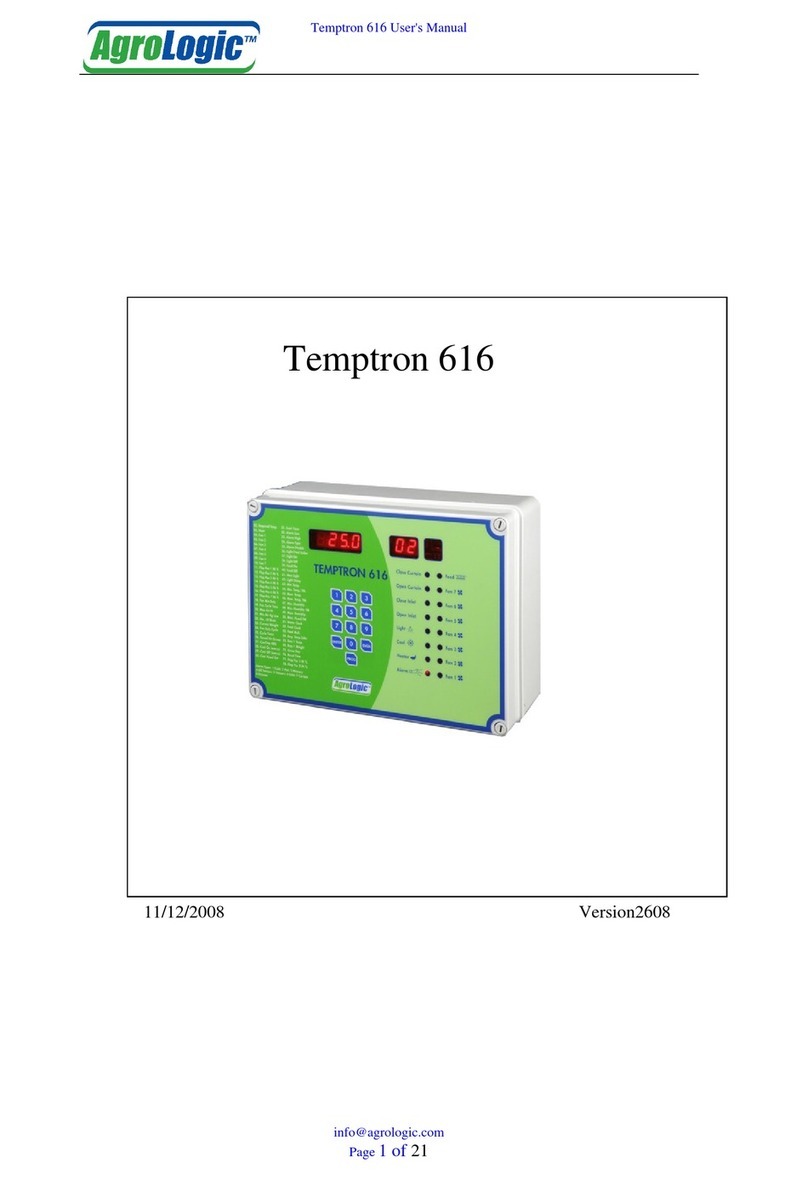
AURATON 2030 RTH User manual


3
Thank you for purchasing this modern, advanced microprocessor-based
AURATON 2030 / AURATON 2030 RTH temperature regulator
8 independently settable temperatures for day and night time –
The AURATON 2030 and AURATON 2030 RTH temperature
regulators allow for setting up to eight independent temperatures
for day and night time with the resolution of one minute. The user
can select time ranges for various temperatures depending on his or
her requirements.
Operation under loads up to 16 A – The AURATON RTH receiver is
equipped with a relay capable of operating with the load up to 16 A.
Its low-sparking technique of switching mains voltage contributes
to the low wear of relay contacts.
Calibration of temperature indications (offset) – Allows for
correcting temperature measurements within the range of ±3°C.
Interference-free communication between devices –
The transmitter and the receiver of the AURATON 2030 RTH set
communicate using the frequency of 868 MHz. Very short,
encrypted data transmission packets (approx. 0.004 s) ensure very
efficient and interference-free operation of the device.
Backlit LCD display – The backlit LCD display allows for supervising
operation of the device even in a poorly lighted room. (Features
3 selectable backlight colours)
LCD
AURATON H-1
Window handle (sold separately)
A window handle, equipped with a position sensor and
a transmitter, is an optional element of the system. This way the
handle provides information about the state of the window.
The handle also differentiates between 4 widow positions:
opened, closed, pivoted and trickle ventilated (micro-
ventilation). The handle transmits information to the RTH
receiver that controls the relay, e.g. switching off a heater in the
event of opening the window or lowering the temperature down
to 3 °C to conserve energy. One RTH receiver operates with max
25 handles.
Optional elements of the system
AURATON T-2
Thermometer (sold separately)
An optional element of the system allowing for controlling
temperature in a room other than that with the AURATON 2030
RTH regulator.

Description of the AURATON 2030
and 2030 RTH temperature regulator
battery holder
(AA LR6 1.5 V)
LCD display programming
buttons
operating modeselection
buttons
RESET
button
fastening
hole
On the right side of the front panel of the regulator you will find a sliding
cover. There are buttons under the cover. You can replace batteries by
removing the cover completely.
4
Display
1234
12
5 6 7 8 9 10 11
13
1. Day of week ( )
Indicates the current day of week. Every day is assigned a number.
2.Temperature
In the normal mode of operation, the regulator displays the temperature in
the room it is installed in.
3.Temperature unit
Informs that the temperature is displayed in degrees Celsius (°C).
4. Clock
Time is displayed in the 24-hour format.
5. Program number ( )
Shows the total number of user-defined programs saved on the regulator.
6. Setting mode indicator ( )
The word SET appears when the user changes one of the following settings
of the thermostat:
- temperature - time
- day of week - program
7. Manual control indicator ( )
Appears when leaving the program-based mode of operation.
8. Anti-freeze mode indicator ( )
Indicates that the regulator operates in the anti-freeze mode.
9. Vacation mode indicator ( )
Indicates that the regulator operates in the vacation mode.
(See chapters: “Temperature programming” and “Vacation mode”).
10. Low battery ( )
This indicator will be visible when the battery voltage drops below the
minimal allowable level. In such an event, replace the batteries as soon as
possible.
NOTE: In order to preserve the parameters programmed, duration of the
replacement operation must not to exceed 30 seconds.
11. Transmission symbol ( ) – AURATON 2030 RTH only
Indicates ongoing communication with the RTH receiver.
12. Relay activation indicator ( )
A segment informing about the operating state of the controlled device.
Visible when the controlled device is turned on (e.g. a heater).
13. Information about operation of the regulator ( INFO )
- current program settings
- relay operating time during the last 24 hours,
- total operating time of the relay since the start of the regulator.
NOTE: “RESET” causes both operating time counters to be set to zero
(INFO 24H, INFO TOTAL).
5

6 7
AURATON RTH
cable tie clamp
control connection terminal
(a terminal for fastening a two-core
cable of the heating or air conditioning
device to be controlled
button for deregistering
already paired devices
button for pairing devices
with the RTH receiver
LED indicating operation
of the device
cable tie clamp
power supply terminal
~230 VAC
legend
The LED light’s green – the output device is off (the contacts COM
and NC are closed).
The LED light’s red – the output device is on (the contacts COM and
NO are closed).
The LED flashes green – the RTH receiver awaits the device
to be paired (chapter: “Pairing the AURATON 2030 RTH wireless
regulator and the RTH receiver”).
The LED flashes red – the RTH receiver awaits the device
to be deregistered (chapter: “Deregistering the regulator from the
RTH receiver”).
The LED flashes alternating red and green:
ALARM - the RTH receiver has lost connection with one of the paired
devices (chapter “Special situations”).
RESET - receiver deregisters all previously paired devices - (chapter
“Deregistering all devices paired with the RTH receiver”).
Legend - description of LED signalling
hole for fastening the receiver
to the wall with a screw
hole for fastening the receiver
to the wall with a screw
Description of the AURATON RTH receiver
The AURATON RTH receiver cooperates with the AURATON 2030 RTH wireless
receiver. The receiver is installed on the heating or air conditioning device and can
operate under the load of 16 A.
Connecting cables to AURATON 2030
Proper operation of the regulator is greatly affected by its location. Installing
it in a place with no air circulation or exposed to direct sunlight causes
improper regulation of temperature. In order to ensure proper operation,
the regulator must be installed on an interior wall of a building (partition
wall). A place should be selected that is occupied most frequently, providing
undisturbed circulation of air. Avoid heat radiating devices (television set,
heater, refrigerator etc.) or places exposed to direct sunlight. In order to avoid
vibration, do not place the regulator in close vicinity of doors.
Selecting the proper location for the
AURATON 2030 / 2030 RTH temperature regulator
Cable terminals are located on the rear wall of the regulator. This is a typical
Single Pole Double Throw relay. In the majority of applications the NC
terminal is unused.
COM
NO
NC

8 9
Fastening the temperature regulator to the wall
1.Drill two holes 6 mm in diameter in the wall (use the template attached
to the manual to mark the spacing between these holes).
2.Insert plastic wall plugs (included in the kit).
3.Screw in the left screw with a 3 mm clearance.
4.Put the regulator over the screw head and slide it to the left (pay attention
to the key-hole in the rear wall of the regulator).
NOTE: If the wall is wooden, there is no need to use wall plugs. In such a case,
drill two holes 2.7 mm in diameter instead of 6 mm, and screw the
screws directly into the wood.
5.Screw in the right screw, making sure it holds the regulator securely.
3. Connect the heating device to the
control connection terminals of the
AURATON RTH receiver.
Proceed in accordance with the service
manual of the heating device. Most
commonly, the COM (common) and NO
(normally open) terminals.
4. Connect power supply conductors to the
power supply terminals of the AURATON
RTH receiver, observing safety rules.
5. After connecting the conductors, they must
be secured with the cable tie clamps and
reinstall protective covers of the AURATON
RTH receiver.
Fastening the RTH receiver
1. Take off protective covers from the lower
and upper part of the AURATON RTH
receiver.
2. Take off cable tie clamps from the lower
and upper part of the AURATON RTH
receiver.
protective cover
cable tie clamp
NOTE: When installing the AURATON RTH
receiver its power supply must be
disconnected. It is recommended that the
installation is performed by a qualified
specialist.
NOTE:
The permanent electrical system
of a building must include a breaker
and an overcurrent protection.

10 11
To fasten the AURATON RTH receiver to the wall:
1) Remove protective covers from the lower and upper part of the regulator.
(See chapter: “Fastening the RTH receiver”).
2) On the wall, mark the location of holes for fastening screws.
3) In marked places, drill holes of a diameter corresponding to the bundled
wall plugs (5 mm).
4) Insert wall plugs into the drilled holes.
5) Screw in the RTH receiver to the wall with screws, making sure they hold the
receiver securely.
Fastening the RTH receiver to the wall
NOTE: If the wall is wooden, there is no need to use wall plugs. In such a case,
drill two holes 2.7 mm in diameter instead of 5 mm, and screw
the screws directly into the wood.
AURATON RTH
hole for fastening
the receiver to the wall with a screw
NOTE:The RTH receiver cannot be placed in metal containers
(e.g. an assembly box, a metal enclosure of a heater) in order to not to
interfere with its operation.
hole for fastening
the receiver to the wall with a screw
3. A properly completed pairing process is signalled by the LED on the AURATON
RTH receiver no longer flashing green and the receiver reverting back to normal
operation.
In the event of an error during the pairing process, repeat steps 1 and 2. Should
more errors occur, deregister all devices by executing the RESET function of the RTH
receiver (see “RESET - Deregistering all devices paired with the RTH receiver”)
and attempt to pair the device again.
NOTE: One receiver can have only one temperature regulator assigned.
Pairing the AURATON 2030 RTH wireless
temperature regulator with the RTH receiver
1.The process of pairing the 2030 RTH regulator with
the RTH receiver is initiated by pressing the left
pairing button (marked with a green triangle - )
on the RTH receiver and holding it for at least
2 seconds, until the LED starts flashing green,
and then releasing the button.
The AURATON RTH receiver waits for pairing
for 120 seconds. After that time, it automatically
returns back to normal operation.
2. On the AURATON 2030 RTH regulator, press the button and hold it for
5 seconds until the transmission symbol ( ) appears on the display. Release
the button - the regulator transmits the pairing signal for 5 seconds.
PROG
radio
Deregistering the regulator from the RTH receiver
1.Deregistering the 2030 RTH regulator from the RTH
receiver is initiated by pressing the right deregistering
button (marked with a red triangle - ) on the
RTH receiver and holding it for at least 2 seconds, until
the LED starts flashing red, and then releasing
the button.
The AURATON RTH receiver waits for deregistering for
120 seconds. After that time, it automatically returns
back to normal operation.
....
NOTE: The AURATON 2030 RTH wireless temperature regulator sold with the
AURATON RTH receiver is already paired. Devices sold separately
require “pairing”.
LED
LED

12
2. On the AURATON 2030 RTH regulator, press the button and hold it for
5 seconds until the transmission symbol ( ) appears on the display. Release
the button - the regulator transmits the pairing signal for 5 seconds.
radio
– Monday Saturday
– Tuesday – Sunday
– Wednesday
– Thursday
– Friday
–
After the proper placement of batteries in
the battery holder, all segments of the LCD
display are displayed (display test) for one
second and after that, the software version
number is displayed.
Following that, the regulator automatically
enters the time setting mode; the hour
field flashes, prompting for setting it.
Using the ‚ and buttons, set the
desired hour value and confirm the setting
with the button.
Using the‚ buttons, set the desired
minute value and confirm the setting with
the button.
In the upper part of the display, the day of
week symbol starts flashing. Using the‚
buttons, set the desired day of week
and confirm the setting with the
button
[up] [do]
[OKOK]
[updon]
[OKOK]
[updo]
[OKOK]
Starting-up the regulator for the first time
13
NOTE:
1) If no button is pressed in 60 seconds when setting the hour value for the
first time, the regulator will automatically assume default time of 12:00
and Monday ( ) as the day of week.
2) When programming any other functions, failing to press any button in 10
seconds is equivalent to pressing the button .[OKO]
3. A properly completed deregistering process is signalled by the LED on the
AURATON RTH receiver no longer flashing red and the receiver reverting back
to normal operation.
In the event of an error during the deregistering process, repeat steps 1 and 2.
Should more errors occur, deregister all paired devices (see “RESET - Deregistering
all devices paired with the RTH receiver”) and attempt to pair the device again.
RESET - Deregistering all devices paired
with the RTH receiver
In order to deregister all devices paired with
the RTH receiver, simultaneously press both
the pairing and the deregistering button
( and ) and hold them for at least
5 seconds until the LED flashes alternating
red and green. Then release both buttons.
A properl y comple ted process of
deregistering all devices is signalled after
approx. 2 seconds by the LED colour
changing to green and then switching it off
for a short period of time.
.. ..
Signalling operation and reception
of data packet
Each radio transmission received by the AURATON RTH receiver from the paired
device is signalled by a temporary change of LED colour to orange. Switching on
the relay is signalled by the LED lit red, whereas switching it off is signalled by the
LED lit green.
LED
NOTE: If after executing the RESET function the RTH receiver is disconnected
from power supply and then connected again, the receiver will automatically
enter “pairing” mode for 120 seconds. A newly purchased RTH receiver without
any factory-paired devices (i.e. not the one bundled with the regulator) will
behave the same way.

In order to set the day of week:
1. Press and hold the button until the
icon is displayed, informing that the
regulator has entered the day of week
setting mode and one of the digits
representing days of week starts
flashing.
2. Using the‚ buttons, set the
desired day of week.
3. Confirm the setting with the
or button.
[1-7]
[set]
[updo]
[okok]
[1-7]
14
Setting the clock
Setting the day of week ...
In order to set the clock:
1. Press the button until the
icon is displayed, informing that the
regulator has entered the time setting
mode, and the hour field starts flashing.
2. Using the‚ buttons, set the
desired hour value.
3. Then press the or button
again, and when the minute field starts
flashing, set ( ) the desired
minute value.
4. Confirm the setting with the
or button.
[cl] SET_z
[updo]
[OKOK] [cl]
up dow
[OKOK]
[clo]
LO / HI temperature
If the surrounding temperature is lower than 5°C,
the display shows “LO”.
If the surrounding temperature is higher than
35 °C, the display shows “HI”.
15
The memory of the regulator allows for saving up to eight programs for
weekdays, eight programs for Saturday and the same for Sunday.
This allows for exceptionally precise planning of temperature in the building
depending on the time of day.
PROGRAMMING
Factory programs (for modification)
Weekdays Saturday Sunday
Prog.
6:00
8:30
15:00
23:00
21°C
20°C
21°C
19°C
Start
time Temperature Prog.
6:00
23:00
21°C
19°C
Start
time Temperature Prog.
6:00
23:00
21°C
19°C
Start
time Temperature
In order to start programming:
Press and hold the button until the
flashing icon is displayed.
1. Selecting a program:
Using the‚ buttons, select the
desired program number to
which you will assign the following
parameters:
- temperature setpoint,
- day of week it applies to,
- starting time.
Dashes are displayed on positions
corresponding to temperature and time
until the program is set.
[PROG]
[SET]
[updo]
[ 1-8 ]

16
5.Repeat the procedure for consecutive programs.
Confirm selection by pressing the button.[okok]
17
3. Assigning temperature to the program :
Press the butto n to assign
temperature to the program.
The icon will start flashing,
prompting for setting the temperature.
Set the desired temperature, using the‚
buttons.
Confirm the setting by pressing the
button.
The icon and the number of
currently edited program will start
flashing on the display again.
4. Assigning starting time to the program:
Press the button. The icon will
start flashing, prompting for setting the
time.
Set the desired starting time for the
program, using the‚ buttons.
Confirm the setting by pressing
the button.
The icon and the number
of currently edited program will start
flashing on the display again.
[T]
[set]
[updo]
[okok]
[set]
[cl] [set]
[updow]
[okok]
[set]
NOTES:
1) Programs with the same program numbers, but assigned to other days of
week can have completely different settings.
E.g.: program 1 on Saturday can start at 08:00, and program 1 on Sunday can
start at 10:00.
2) Days from to (from Monday to Friday) have the same programs.
3) On the same day of week, the next program should start at least a minute
after the start of the previous one. Otherwise the regulator will renumber
the programs in order to preserve the chronology of temperature setpoints.
4) For the selected day of week, the period of temperature programming
cannot exceed 24 hours – the last program can start no later than a minute
after the first one.
5) When all programs are inactive, the regulator remains turned off.
(1) (5)
DELETING A PROGRAM:
To delete a selected program, set “dashes” in the
temperature field.
2. Assigning a day to the program :
Press the button to select days to
be assigned to the program. A segment
with days of week will start flashing in the
top part of the display.
Using the, buttons, you can
assign:
– for week days
– for Saturday
– for Sunday
Confirm selection by pressing the
button .
The icon and the number of
currently edited program will start
flashing on the display.
[1---7]
[updo]
[okok]
[SET]
1. Press the button and wait until
flashing icon is displayed with
the symbol of the currently edited kind
of temperature.
2. Pressing the button again will
toggle the currently edited kind of
temperature.
[Te]
[SET]
[Te]
3. Set the desired temperature value in
the currently edited kind of tempe-
rature, using the‚ buttons.
4. After setting all temperature kinds,
confirm the setting by pressing
the button.
[updo]
[okok]
Programming the manual , vacation
and anti-freezing temperature.
The AURATON 2030 / AURATON 2030 RTH regulator allows for setting three
kinds of temperature:
manual temperature ( ) – within the range from 5°C to 30°C,
vacation temperature ( ) – within the range from 5°C to 30°C,
anti-freeze temperature ( ) – within the range from 4°C to 10°C.
To set one of the above mentioned temperatures:

18
Manual control
When, for any reason, you would like to suspend execution of the program for
a certain period of time, the temperature can be set manually for a specified
time. In such a case you have to:
1. Press the button. This will cause the and icons to appear
flashing on the display. The temperature field will become editable, with
the previously programmed value set as default.
Use the‚ buttons to edit the value, and the button to
confirm settings.
2. To leave the manual control mode, press the button.
[auto] [set.] [ha]
[updow] [okok]
[auto]
Vacation mode
Should there be a need for suspending execution of the programs for
a prolonged time, the vacation mode can be used.
When this option is active, the regulator executes only the “vacation
temperature” (see chapter: “Temperature programming”).
Maximal duration of operation in vacation mode is 6 days, 23 hours and 59
minutes.
In order to enter the vacation mode:
1. Press the button and hold it for
3 seconds.
This will cause flashing of the and
icons as well as the field time.
2. Using the‚ buttons, set the time
when the vacation mode should end.
3. By pressing the button you can set
the day when the vacation mode should
end.
The icon will start flashing on the
display. Using the, buttons, set
the day when the vacation mode should
end.
4. Confirm the setting by pressing
the button.
[auto]
[set]
[dri]
[updow]
[1-7]
[set ]
[updo]
[okok]
Switching off the receiver for a period of time
Pressing the button and holding it for 5 seconds causes switching off
the thermostat relay, setting the temperature in the receiver to 4°C and
putting out all elements on the display except for current temperature, time
and day of week.
To restore normal operation of all functions of the regulator, press
the button.
[powe]
[powe]
19
Anti-freeze mode
The regulator is equipped with a setpoint for the anti-freeze temperature.
This setpoint can be set within the range from 4 to 10°C. (Factory set at 7°C)
The anti-freeze mode is used during a prolonged period of absence or outside
the heating season and is designed to prevent water in the heating system
from freezing.
1. To enter the anti-freeze mode, press the button. The “ ” icon
will appear on the display.
2. To leave the anti-freeze mode press the or button.
[powe] sno
[auto] [powe]
The “ ” symbol will be displayed on the screen while the vacation mode is
active. You can leave the vacation mode earlier by pressing the button. [auto]
Viewing the currently active program
Pressing the button in the normal operation mode causes the INFO
segment and all the parameters of the currently executed program
(day of week, temperature and ending time) to flash for 10 seconds
on the display.
To restore the regulator back to normal operation, press the button
again.
[okoko]
[okok]
Relay operating time counter
Pressing the button and holding it for 3 seconds activates
the INFO 24H function that counts the relay operating time during the last 24
hours.
Pressing the button again causes the INFO TOTAL segment to appear,
corresponding to the function of counting the accumulated number of days
of relay operation.
To restore the regulator back to normal operation, press the button
again.
NOTE: To reset the total counter of days of relay operation to zero, press
the button and hold it for 5 seconds, while in the INFO TOTAL
mode.
NOTE: “RESET” causes both operating time counters to be et to zero.
[okok]
[okoko]
[okoko]
[okoko]

20
Configuration settings:
backlight colour, hysteresis, delay, offset
Configuration settings are presented for changing in the following order:
To enter the configuration settings change mode press the‚ buttons
simultaneously and hold them for 5 seconds until the display backlight starts
flashing.
1.BACKLIGHT COLOUR CHANGE:
Flashing backlight indicates that you
can change the backlight colour with
the buttons.
Confirm the setting by pressing the
button.
The regulator will proceed to change
the next parameter.
2. HYSTERESIS CHANGE:
Hysteresis is designed to prevent switching the controlled device on and
off too frequently due to minute fluctuations of temperature.
E.g. for the HI 2 hysteresis, when the temperature is set to 20°C, the boiler
will be switched on at 19.8°C, and switched off at 20.2°C. For the HI 4
hysteresis, when the temperature is set to 20°C, the boiler will be switched
on at 19.6°C, and switched off at 20.4°C.
The hysteresis change mode is signalled
by flashing text “HI”. You can change
hysteresis settings with the
buttons.
HI 2 – ±0,2°C
HI 4 – ±0,4°C
HI P – PWM mode (see chapter “PWM mode”)
Confirm the setting by pressing the button.
The regulator will proceed to change the next parameter.
[updow]
[updo]
[okok.]
[upd]
[okoo]
(factory setting)
21
3. DELAY CHANGE (AURATON 2030 only)
Delay is designed to prevent switching the controlled device on and off too
frequently e.g. due to a momentary whiff of air caused by opening
a window.
This mode is signalled by flashing text
”90:SE”. You can switch the delay on and off
with the buttons.
90:SE – 90s delay
(factory setting)
0:SE – without delay
Confirm the setting by pressing the button. The regulator will
proceed to change the next parameter.
4. OFFSET CHANGE
Offset allows for calibrating temperature indications within the tolerance
of ±3°C.
E.g. the temperature regulator indicates that the room temperature is 23
°C, whereas a regular mercurial thermometer placed alongside indicates
24 °C. Changing offset by +1 degree makes the regulator indicate the same
temperature as the mercurial one.
The offset change mode is signalled by
flashing text OFFS.
You can set the desired value ( )
within the range from 3.0 to 3.0 (factory
setting is 0.0).
Confirm the setting by pressing the
button. The regulator will resume normal
mode of operation.
NOTE: If no button is pressed for 10 s while changing configuration
settings, the regulator will resume normal mode of operation.
[updo]
[okok]
updow
[okok]
backlight
colour change
hysteresis
change
delay
change
(AURATON 2030 only)
offset
change
PWM operation mode (Pulse-Width Modulation)
When changing hysteresis settings, you can enable PWM mode. In PWM
mode, the controller switches on the heating device in cycles to minimize
temperature fluctuations.
Th e c o nt r o ll e r m on ito r s t h e
temperature rise and drop time.
With these values determined, the
controller switches the heating
device on and off in cycles that enable
maintaining temperature as close to
the setpoint as possible.
Temp.
Time
Set
temp.
Temperature
in the room
This manual suits for next models
1
Table of contents
Other AURATON Temperature Controllers manuals
