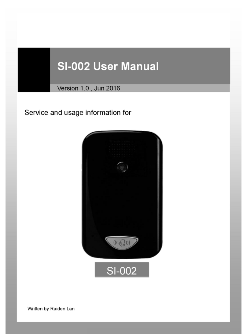
ProTalk PT-Door01 User manual

ProTalk Door Entry System
PT-Door01
PT-Door01C
PT-Door02
PT-Door02C
PT-Door01CAV
1 | P a g e

Installation and User Manual
ELCOME
Congratulations on purchasing the ‘ProTalk Door Entry’ system. This system will fulfil all your
business, an home, oor entry communication nee s. The ProTalk Door Entry system connects to
your computer network an allows either peer to peer (P2P) calls (calls irect to an IP a ress of
another VoIP evice) or calls to another number via the SIP server.
There are several basic mo els to choose from; a one button system, a two buttons system or a
system with an integrate colour camera. There is also an Anti-van al system in ano ize
aluminium.
The unit is powere by either an AC/DC 12V power supply, which can also power an electric oor
lock, or via a ‘Power over Ethernet’ (PoE) system.
The basic ProTalk Door Entry system inclu es an option to open, up to, two oors with electric
locks. The system is easily programme via a user interface which is accesse via a web browser.
The manufacturer constantly improves the firmware of this pro uct. The system can
ownloa the latest version at any time with the help of an or inary computer, the latest
firmware is available at http://protalk.provu.co.uk/firmware/
You will fin the instructions how to o this on page 22 of this manual. We recommen that
you always ownloa the latest version available to get the best out of the pro uct features.
2 | P a g e

TABLE OF CONTENTS
1 BASIC DESCRIPTION 5
1.1 Features 5
1.2 Terminology 5
1.3 Mo ules 7
1.4 Unit features 7
1.4.1 Door Entry System - Basic Unit 7
1.5 Door Entry System assembly 11
1.5.1 Front cover assembly and disassembly 11
1.5.2 Name tag back lighting disassembly 12
1.5.3 Wall mounting 12
1.5.4 Return of name tags after all mounting 13
1.5.5 Name tag change 13
2 DOOR ENTRY SYSTEM OPERATION 14
2.1 Signalling 14
2.2 Caller at the oor 14
2.3 Person in the buil ing 15
2.3.1 Outbound call 15
2.3.2 Incoming call 15
3 PARAMETER PROGRAMMING 16
3.1 Basic VoIP settings 16
3.1.1 Choice of mode and sign in 16
3.1.2 Language setting 17
3.1.3 Net ork settings 18
3.1.4 Peer to peer or SIP server connection 19
3.1.5 Audio codec setting 21
3.1.6 Video setting 22
3.1.7 Video vie ing (programme Pop-Up) 22
3.1.8 Day intervals 23
3.1.9 User interface 24
3.1.10 Service settings 25
3.1.11 Restart 26
3.1.12 Preparation style, language support 26
3.2 Door Entry System parameter setting 27
3.2.1 Basic Parameters 27
3.2.2 All about relays 28
3.2.3 Time Parameters 30
3.2.4 Direct Dialling – Memory numbers 31
3 | P a g e

4 TECHNICAL PARAMETERS 32
4.1 Electrical parameters 32
4.2 Mechanical parameters 32
4.3 Vi eo parameters 32
4 | P a g e

1 BASIC DESCRIPTION
1.1 Basic Features
Door Entry Control Unit:
•Buttons to ial extensions or groups;
•Options for single/ ouble buttone which call ifferent numbers/groups
•Backlit buttons;
•Two internal SPDT relays for controlling a oor opener or light etc.
•Relays controlle in ivi ually by DTMF tones; an
•SIP Protocol.
Unit with IP cam ra (as abov with):
•Optional real-time IP camera viewe via a computer terminal;
•View an talk to callers as well as opening the oor remotely; an
•Camera permanently operational, not just uring calls.
ProTalk Support Kits:
•A range of electronically controlle oor evices to connect to the oor phone;
•12v power supplies with battery backup option;
•Exit Relays; or
•Bun les [of above] as complete oor entry kits.
1.2 Terminology
•Ethernet is a family of frame-base computer networking technologies for local area
networks (LANs).
•A local area network (LAN) is a computer network covering a small physical area, such as
home, office or small group of buil ings, such as a school or an airport
•10BASE-T runs over four wires (two twiste pairs) on a Category 3 or Category 5 cable.
•100BASE-TX Uses two pairs, but requires Category 5 cable (FastEthernet)
•Twisted pair cabling is a form of wiring in which two con uctors (the forwar an return
con uctors of a single circuit) are twiste together for the purposes of cancelling out
electromagnetic interference (EMI) from external sources.
5 | P a g e

•UTP (unshiel e twiste pair) cable is not surroun e by any shiel ing.
•STP (shiel e twiste pair) cables are often shiel e in attempt to prevent electromagnetic
interference.
•The orld ide eb (commonly abbreviate as the " eb") is a system of interlinke
hypertext ocuments accesse via the Internet.
•Hypertext Transfer Protocol (HTTP) is an application-level protocol for istribute ,
collaborative, hyperme ia information systems.
•Universal Serial Bus (USB) is a serial bus stan ar to connect evices to a host computer.
•A video codec is a evice or software that enables vi eo compression an /or ecompression
for igital vi eo. H.264 is a stan ar for vi eo compression, an is equivalent to MPEG-4 AVC.
H.263 is a vi eo co ec stan ar originally esigne as a low-bitrate compresse format for
vi eoconferencing. MPEG-4 is collection of metho s efining compression of au io an visual
(AV) igital ata.
•JPEG is a commonly use metho of compression for photographic images.
•Voice over Internet Protocol (VoIP) is a general term for a family of transmission
technologies for elivery of voice communications over IP networks such as the Internet.
•The Internet Protocol Suite (commonly known as TCP/IP) is the set of communications
protocols use for the Internet
•An Internet Protocol (IP) address is a numerical i entification an logical a ress that is
assigne to evices participating in a computer network utilizing the Internet Protocol for
communication between its no es.
•Dynamic Host Configuration Protocol (DHCP) is a network application protocol use by
evices (DHCP clients) to obtain configuration information for operation in an Internet
Protocol network.
•The Internet is a global system of interconnecte computer networks that use the
stan ar ize Internet Protocol Suite (TCP/IP).
•An intranet is a private computer network that uses Internet technologies
•Power over Ethernet or PoE technology escribes a system to transfer electrical power, along
with ata, to remote evices over stan ar twiste -pair cable in an Ethernet network
•Network Time Protocol (NTP), a means of synchronizing clocks over a computer network.
6 | P a g e

1.3 Models
There are several options of ‘ProTalk Door Entry System’ units to choose from, namely:
PT-Door 01 PT-Door 02 PT-Door 01C PT-Door 02C
(PT-Door 01CAV)
1. A one buttone unit (PT-Door 01);
2. A twin buttone unit (PT-Door 02);
3. A one buttone unit with colour camera (PT-Door 01C);
4. A twin buttone with colour camera (PT-Door-02C); an
5. An Anti-van al Unit with ano ize aluminium cover to protect against van alism, this unit is
only available as a one button unit with colour camera (PT-Door 02CAV).
1.4 Unit Features
1.4.1 Door Entry Syst m - Basic Unit
The Door entry system internals consist of; a motherboar , an IP mo ule, a PoE mo ule an a
camera, see pictur 1 for the setting an positioning of the mo ules.
We recommen that the system is powere by PoE technology, Alternating Current (AC 11Vts min.
15Vst max) or Direct Current (DC 12Vss min 18Vss max) connecte via the ‘12V’ connector (as per
pictur 1). The maximum power loa is 300mA, epen ing on the number of mo ules; you may also
use this power source to power the electric locks. In practice an AC 12V/1A woul meet your
eman s.
The Door entry system is fitte with a UTP cable socket/PoE. If your network switch is fitte with a
PoE power supply or you have a separate PoE power supply (usually a small box, the size of network
a aptor at the en of the UTP cable) you won’t nee the 12V supply as well.
7 | P a g e

If you opt to use a high powere electrically operate oor mechanism you will nee to provi e a
separate power supply to the relay circuit. Alternatively, you coul utilise a low powere lock
mechanism, which can be connecte via the powere oor bell (backlight) with the PoE system, as
there is sufficient power available in this system to accommo ate this (please see picture 4).
Pictur 1 Moth rboard
The connection of relay contact terminals is illustrate on pictur 2. The “NO” annotation means an
i le- isconnecte contact, “COM” means a pin contact (mi le) an “NC” means an i le-connecte
contact. The contacts of both connectors are galvanic insulate from each other an also from other
circuit contacts.
The alternative connections are shown on pictur 3 an 4.
The camera can be tilte vertically (up an own) so that the optimal picture can be achieve .
8 | P a g e

Pictur 2 - Conn ction of th Door Entry Syst m
9 | P a g e

Pictur 3 - Conn ction of R lay Contact T rminal without PoE Pow r Sourc
Pictur 4 - Conn ction of R lay Contact T rminal with PoE Pow r Sourc
NB. with low powere lock mechanism, max 350mA.
Voic Communication S tting
Volume settings have been preset by the manufacturer. The preset position is shown on pictur 5. If
changes are require these can easily be ma e by using the trimmers accor ingly. As the system works as a
phone the transmission may result in a voice elay, however, the system is fitte with a circuit for echo
10 | P a g e

attenuation which can also be trimme . The volume level is set such that the microphone will automatically
switch off so that the voice oes not result in an echo, see pictur 5.
The light sensitivity trimmer allows you to set the level of light that triggers when the LED lights come on.
These lights she a itional lighting so that the camera will work at night. The light sensitive sensor is only
active uring the call an automatically switches off at the en .
DIP r lay setting of base parameters an mo e with DIP relay Reserve
1. Change of mo e P2P/SIP server
2. Basic setting – eletes all parameters an changes them to factory setting (apart from
number memory)
3. Sets basic IP a ress to 192.168.1.250
Changes will take effect after restart. DIP relays 3 an 4 must always be switche to the “on” position after
the restart, otherwise the new parameters or IP a ress will be lost an the unit will automatically revert to
the stan ar factory settings.
1.5 Door Entry system assembly
1.5.1 Front-cov r Ass mbly and Disass mbly
11 | P a g e

1.5.2 Nam Tag Back Lighting Disass mbly
1.5.3 Wall Mounting
The unit can be Wall mounte with the enclose screws an wall plugs (screw river iameter
5mm).
12 | P a g e

1.5.4 R turn of nam tags aft r wall mounting
1.5.5 Nam Tag Chang
Each button has a car tag hel in place with a plastic cover (see picture above). Paper name tags of
the correct size can be pro uce in an Excel worksheet if necessary.
13 | P a g e

2 DOOR ENTRY SYSTEM OPERATION
2.1 Signalling
System has operational acoustic signals an also re LED light (place un er the microphone).
Condition Tones Tone Frequency LED
Line pick up 425-850-1275 Light
Line rop 1275-850-425 Dark
Report After Call 425-850-1275 Light
En of Call Alert 425 Light
Confirm Comman 1275 -
Reset (Turn on) 1275-850-1275 Flash
Error (any) 425... -
Memory Empty 850-1275-1700... -
Waiting to be Connecte - - Flash
Line Connecte - - Light
2.2 Caller at the door
The function of the Door entry system is influence by the base setting.
The buttons are equippe with name tags (or functions) of the people in the buil ing. The Caller
press the name button an the system will then pick up the phone, either imme iately (if the first
button is the only number in the co e) or with a small elay (time between the buttons). The
number ialle by the system will epen on the mo e set on the system:
•Mode Day/Night: if the system is in DAY mo e it will ‘always’ ials the number set in the first
column an in NIGHT mo e it will ‘always’ ial number set in the secon column. The
ay/night mo e relay is set in the “co e switch over”. (a new system with a time base ,
automatic ay/night relay is currently in preparation);
•Mode 2 Groups of numbers: the first button press will ‘always’ ial the number in first
column. A repeat press of the same button, in the event of a busy tone, or after set number
of rings (time before call answere an before a repeat choice) the system will automatically
ial the number in the secon column. After a thir press of the same button a number from
the first group is ialle an so on (i.e. after busy a tone in group 2 the repeat ial is
cancelle ).
Shoul the caller press the button after the system has picke up, it will automatically hang up
(“hang up time before repeating option”), in this instance pick a new number.
14 | P a g e

From the System ial it is possible to control the oor relay (co e lock). If the caller presses buttons
in the previously programme combination an in a time previously set in the parameters, the
System will trip the appropriate relay (if it is set in mo es m=1 to m=5) for a given time, previously
set in parameters.
2.3 Person(s) Inside the Building
‘Person(s) insi e the buil ing’ means anyone who is in telephone contact with the Door Entry
System.
2.3.1 Outbound Calls
An ‘outboun call’ is any call from the oor entry System (i.e. from a visitor). When the phone rings
an is pick-up it will be possible to speak with the visitor at the oor, by choosing one of the mo es
(m=1 to m=5, Day/Night mo e, hang up etc). 10 secon s into any conversation the system will issue
an en of call alert, by choosing ‘*/#’ it is possible to prolong the call; the call will then be en e by
hanging up.
There are two ways for information to be transmitte ( oor lock opening, Day/Night mo es,
prolonging the call, comman for hang-up etc); either by “RTP channel” or by “SIP info”, the variant
“in-ban DTMF” isn’t available in this Door Entry System.
2.3.2 Incoming Calls
An ‘incoming call’ is call from the System (i.e. from a visitor). After selecting the number of the
branch or IP a ress where the system is connecte , the System rings (an the LED light will flash).
After set number of rings the system will automatically pick up the call an it is then possible for the
visitor to speak. Otherwise the options are the same as with the outboun calls.
15 | P a g e

3 PARAMETER PROGRAMMING
3.1 Basic VoIP Settings
3.1.1 Choic of Mod and Sign-in
It is important choose the mo e the System will utilise, either P2P (peer to peer) or via a SIP server. The
selection is one using the ‘DIP Relay 2’ (pictur 7). A mo e change is not possible by the WEB interface an
any relay change will only show after a System restart. All other relay shoul be in set in the “on” position.
When switching the System on you will nee to wait for about 1 minute for the System to react.
To restore to the factory settings, switch the ‘DIP Relay 3’ to the “off” position an restart the
System. After restarting the System return relay 3 to the “on” position.
To set the starting IP a ress 192.168.1.250 switch ‘DIP Relay 4’ to the “off” position an restart the
System. After restarting the System return relay 4 to the “on” position.
There are two options to restart the System – either by isconnecting the power supply or by
clicking on “restart” in the WEB interface (in fol er service).
The factory setting IP a ress is 192.168.1.250. If your network a ress numbering system is
ifferent (i.e. it oes not start 192.168.1.xxx), then it will be necessary to set your a ress in the
protocol properties TCP/IP in your PC either provisionally or as alternative configuration (e.g.
192.168.1.245). You can then set the System parameters inclu ing the new IP a ress. After the
VoIP mo ule restart you can then connect to WEB page of the new IP a ress.
DIP relays 3 an 4 must be in the “on” position otherwise the new IP a ress will be change back to
the factory set IP a ress on restart.
Write into your WEB browser IP a ress of the Door Entry System. The efault a ress is
192.168.1.250 as seen on pictur 8 below.
16 | P a g e

Pictur 8 – First pag – vid o from cam ra
Log in using your user name an passwor . The factory set user name is always “a min” an the
passwor is “1234” (these can be change in the settings).
Pictur 9 – Log in to s t up
3.1.2 Languag S tting
The language is set in the bottom part of menu in the left-han panel. You can change an a
languages (see page 22).
17 | P a g e

3.1.3 N twork S ttings
Network setting can be foun in “Network setting”. You can either use a fixe IP a ress or a
ynamically assigne one using the DHCP service.
Fixe IP a ress configuration:
1. Hostname – Name of the System for network ifferentiation (e.g. when using more Systems –
more oor entries);
2. Switch on/off DHCP a ress assignment;
3. IP a ress setting, mask setting, or any other network setting. If you are unsure please
contact your network a ministrator;
4. Display of System in current mo e – Day/Night;
5. Return to main page with vi eo picture from camera;
6. Help – for basic help when setting parameters; an
7. Default values – will perform change back to factory settings. After making changes, press
“save an restore”. System restart screen will come up (see page 26).
Don’t forget to click on “save an restart” after making any changes.
DHCP configuration:
18 | P a g e

1. Hostname - Name of the System for network ifferentiation (e.g. when using more Systems –
more oor entries);
2. Switch on/off DHCP a ress assignment;
3. DHCP client ID – use when two a resses are assigne to one MAC a ress (not applicable
to the Door Entry System);
4. Display of parameters automatically assigne by DHCP – IP a ress an other settings; an
5. Default values –changes all back to factory settings. After making changes, press “save an
restore”. System restart screen will come up (see page 26).
Important: If you are using a DHCP setting, the a ress will be assigne automatically an your
network a ministrator will be able to i entify the actual IP a ress for viewing vi eo from camera
on the web browser. Because this ynamically assigne a ress can change (for example after
power short-cut, it is recommen e you set a fixe IP a ress.
3.1.4 P r to P r or SIP S rv r Conn ction
It is possible to set the Door Entry System to a peer to peer (P2P) mo e or a SIP server mo e with
the DIP Relays (see page 16). In the P2P mo e the System will call the IP a ress save in the
memory (see page 31).
19 | P a g e

1. Choice of incoming signal ring can be change to session progress – a e for some SIP proxy
servers that require this;
2. Symmetric RTP – a e for some SIP proxy servers that require this; an
3. Default values – will perform basic factory reset.
After making changes click on “save changes”.
20 | P a g e
This manual suits for next models
4
Table of contents
