Riedel Artist-1024 User manual

Artist-1024
User Manual
10-005HB01AA-D00
8.4

10-005HB01AA-D00
Artist-1024 8.4 User Manual
© December 2022 Riedel Communications GmbH & Co. KG. ALL RIGHTS RESERVED.
UNDER THE COPYRIGHT LAWS, THIS MANUAL MAY NOT BE COPIED, IN WHOLE OR IN PART, WITHOUT THE WRITTEN CONSENT OF RIEDEL. EVERY
EFFORT HAS BEEN MADE TO ENSURE THAT THE INFORMATION IN THIS MANUAL IS ACCURATE. RIEDEL IS NOT RESPONSIBLE FOR PRINTING OR
CLERICAL ERRORS. ALL TRADEMARKS ARE THE PROPERTY OF THEIR RESPECTIVE OWNERS.
This device complies with Part 15 of the FCC Rules and with Industry Canada licence-exempt RSS standard(s). Operation is subject to the following two conditions:
(1) this device may not cause harmful interference, and
(2) this device must accept any interference received, including interference that may cause undesired operation.
Le présent appareil est conforme aux CNR d'Industrie Canada applicables aux appareils radio exempts de licence.
L'exploitation est autorisée aux deux conditions suivantes: (1) l'appareil ne doit pas produire de brouillage, et (2) l'utilisateur de l'appareil doit accepter tout brouillage
radioélectrique subi, même si le brouillage est susceptible d'en compromettre le fonctionnement.
Changes or modifications made to this equipment not expressly approved by Riedel may void the FCC authorization to operate this equipment.
This equipment has been tested and found to comply with the limits for a Class A digital device, pursuant to Part 15 of the FCC Rules. These limits are designed to provide
reasonable protection against harmful interference when the equipment is operated in a commercial environment. This equipment generates, uses, and can radiate radio
frequency energy and, if not installed and used in accordance with the instruction manual, may cause harmful interference to radio communications. Operation of this
equipment in a residential area is likely to cause harmful interference in which case the user will be required to correct the interference at his own expense.
The device conforms to the following EU guidelines
as attested by the CE mark.
·
EMC 2014/30/EU
·
LVD 2014/35/EU
·
RoHS 2011/65/EU
YFJART1024
Standards
·
EN 50581:2012
·
EN 55032: 2015
·
EN 55035-2:2017
·
EN 61000-3-2:2014, EN 61000-3-3:2013
·
EN 61000-4-2:2009, EN 61000-4-3:2006+A1:2008+A2:2010,
EN 61000-4-4:2012, EN 61000-4-5:2014, EN 61000-4-6:2014,
EN 61000-4-8:2010, EN 61000-4-11:2004
·
IEC/EN 60950-1:2005+A1:2009+A2:2013
·
IEC/EN 62368-1:2014, UL/CSA 62368-1:2014
Industry
Canada
8706A-ART1024

Artist-1024 User Manual V8.4
Content
1Preface 4
1.1 Information ...................................................................................................................... 4
1.2 Safety Instructions .......................................................................................................... 5
1.3 Change History ............................................................................................................... 7
1.4 Firmware Version ........................................................................................................... 7
1.5 About Artist-1024 ........................................................................................................... 8
2Artist-1024 - Node 9
2.1 Frame (MFR-1024) .......................................................................................................... 9
2.1.1 Info Display ................................................................................................. 10
2.1.2 Display Content ........................................................................................... 10
2.1.3 Operation .................................................................................................... 11
2.2 LED Wedge (WDG-1024) .............................................................................................. 12
2.3 Front Filter (FRF-1024) ................................................................................................. 12
2.4 Power Supply (PSU-1024) ............................................................................................ 13
2.5 Fan Unit (FAN-1024) ..................................................................................................... 13
2.6 Technical Drawing ........................................................................................................ 14
2.7 Installation Options ...................................................................................................... 14
2.8 Technical Specification (Frame) ................................................................................. 15
3Artist-1024 - Cards 16
3.1 UIC-128 ........................................................................................................................... 16
3.1.1 Front Elements ............................................................................................ 16
3.1.2 Status LEDs .................................................................................................. 17
3.1.3 Port Types .................................................................................................... 17
3.1.4 Technical Specifications ............................................................................. 17
4Features in Detail 18
4.1 NIC Redundancy ........................................................................................................... 18
4.2 Replacing Front-Filter .................................................................................................. 18
4.3 Replacing Rear-Filter .................................................................................................... 19
4.4 Reversing the Airflow .................................................................................................. 19
4.5 Connections .................................................................................................................. 21
4.6 Recommended SFPs .................................................................................................... 21
5Licensing 22
5.1 License Model ............................................................................................................... 22
5.2 Flexible License ............................................................................................................. 23
5.3 First Steps ...................................................................................................................... 23
5.4 Flexera User Portal ....................................................................................................... 23
5.4.1 Login ............................................................................................................ 23
5.4.2 Forgotten Password .................................................................................... 24
5.4.3 User Profile & Security ................................................................................ 24
5.5 Riedel License Manager .............................................................................................. 25
5.5.1 Login ............................................................................................................ 25
5.5.2 Downloading License .................................................................................. 25
5.5.3 Extending License ........................................................................................ 26
5.5.4 Moving License ............................................................................................ 27
5.6 Installing License .......................................................................................................... 28
6Appendix 29
6.1 Glossary ......................................................................................................................... 29
6.2 Maintenance Recommendations .............................................................................. 30
6.3 Service ............................................................................................................................ 30
Index..... 31

4
Artist-1024 User Manual V8.4
10-005HB01AA-D00
1 Preface
Thank you for choosing a Riedel product.
This PDF document provides detailed information about the Artist-1024 system, pin outs, mechanical and
electrical data.
For further information, please refer to the Riedel Website or contact your local distributor or the Riedel
headquarters in Wuppertal.
NOTICE
This manual, as well as the software and any examples contained herein are provided “as is” and are
subject to change without notice. The content of this manual is for informational purpose only and should
not be construed as a commitment by Riedel Communications GmbH & Co. KG or its suppliers. Riedel
Communications GmbH & Co. KG gives no warranty of any kind with regard to this manual or the software
including, but not limited to the implied warranties of merchantability and fitness for a particular purpose.
Riedel Communications GmbH & Co. KG shall not be liable for any errors, inaccuracies or for incidental or
consequential damages in connection with the furnishing, performance or use of this manual, the software
or the examples herein. Riedel Communications GmbH & Co. KG reserves all patent, proprietary design,
title and intellectual property rights contained herein, including, but not limited to, any images, text,
photographs incorporated into the manual or software.
All title and intellectual property rights in and to the content that is accessed through use of the products is
the property of the respective owner and may be protected by applicable copyright or other intellectual
property laws and treaties.
1.1 Information
Symbols
The following tables are used to indicate hazards and provide cautionary information in relation to the
handling and use of the equipment.
Danger
!
Indicates an imminently hazardous situation which, if not avoided, will result in death or
serious injury.
The highlighted line indicates the activity to prevent the danger.
Warning
!
Indicates a potentially hazardous situation which, if not avoided, could result in death or
serious injury.
The highlighted line indicates the activity to prevent the danger.
Caution
!
Indicates a potentially hazardous situation which, if not avoided, may result in minor or
moderate injury. It may also be used to alert against unsafe practices.
The highlighted line indicates the activity to prevent the danger.
This text is for generally information. It indicates the activity for ease of work or for better
understanding.

5
Artist-1024 User Manual V8.4
10-005HB01AA-D00
1.2 Safety Instructions
Service
·
All service has to be undertaken only by qualified Riedel service personnel.
·
Do not plug in, turn on or attempt to operate an obviously damaged device.
·
Never attempt to modify the equipment components for any reason.
Caution
!
All adjustments have been done at the factory before the shipment of the devices. No
maintenance is required and no user serviceable parts are inside the module.
Ventilation
·
Keep front and rear of the frame always closed.
Bays without cards must be covered with blind plates.
·
Do not place the device next to a hot source like a radiator.
·
Ventilation openings in the front and rear must never be blocked.
Environment
·
Never place containers with any liquids on top of the devices.
·
Never place the devices in areas of high dust particles or humidity.
·
Be aware of the operating temperature of the systems (0 … +45 °C / 32 ... 113 °F).
·
If the equipment has been exposed to a cold environment and transferred to a warm environment,
condensation may form inside the housing. Wait at least 6 hours before applying any power to the
equipment.
Voltage
·
The power cable should only be connected to a correctly grounded source.
·
Do not use any adapters.
·
Never bypass a ground contact.
·
The mains plugs is used as a disconnect device. It is imperative that access to the mains plugs and
the associated mains socket/outlet is never obstructed.
Danger
!
To reduce the risk of electric shock do not remove cover or expose the products to rain
or moisture.
Caution
!
Frames do have redundant Power supplies.
To shut down the unit completely, remove both power cords.
Warning
!
·
Laite on liitettävä suojakoskettimilla varustettuun pistorasiaan.
·
Apparatet må tilkoples jordet stikkontakt.
·
Apparaten skall anslutas till jordat uttag.
·
Apparatets stikprop skal tilsluttes en stikkontakt med jord som giver forbindelse til
stikproppens jord.
ESD Safety
Device components shipped in antistatic bags are sensitive to damage from static electricity. You can
easily generate potentially harmful static voltages when handling plastic or foam packaging or moving
components over plastic or carpets.
Please observe the following guidelines to avoid damage from electrostatic discharge (ESD), which may
result in failures or destruction of components:
·
When handling open cards, use an ESD wristband and ensure that it is in direct contact with your
skin.
·
If there is no grounding strap available, touch a grounded metal surface before removing or
inserting the card from a device.
·
Avoid contact between the cards and your clothing. ESD voltages emitted from clothing can damage
components.
·
When removing or installing a card, always place it with the heat sink facing upwards on an
antistatic surface or in an ESD bag.
·
When returning cards, put them in an ESD bag before packing it.

6
Artist-1024 User Manual V8.4
10-005HB01AA-D00
Laser Safety
Artist-1024 devices / cards can be equipped with optical fiber modules (FOM) for the data transmission
over a fiber.
Observe the following guidelines and warnings:
·
Because invisible radiation might be emitted from the aperture of SFPs when no fiber cable is
connected, avoid exposure to radiation and do not stare into open apertures.
·
Do not look at fibers that connect to unknown sources.
·
Do not examine unterminated optical ports with optical instruments.
·
Avoid direct exposure to the beam.
LASER CLASS 1 PRODUCT
APPAREIL A LASER DE CLASSE 1
LASER KLASSE 1 PRODUKT
The laser transceivers are considered as a class 1 laser
product per EN 60825-1, FDA 21 CFR1040.10 and 1040.11
requirements.
Caution
!
The accessible laser radiation is harmless under reasonably foreseeable conditions. Note:
The reasonably foreseeable conditions are met during normal operation.
The limit value of the accessible radiation of DIN EN 60825-1:2001-11 in the
wavelength range from 400 nm to 1,400 nm for the classification of a laser is the
same between 100 s and 30,000 s. Therefore, nuisances cannot be ruled out in the
case of long-term effects.
Disposal
Disposal of old Electrical & Electric Equipment (Applicable throughout the European Union and other
European countries with separate collection programs).
This symbol, found on your product or on its packaging, indicates that this product
should not be treated as household waste when you wish to dispose of it. Instead, it
should be handed over to an applicable collection point for the recycling of electrical
and electronic equipment. By ensuring this product is disposed of correctly, you will
help prevent potential negative consequences to the environment and human health,
which could otherwise be caused by inappropriate disposal of this product. The
recycling of materials will help to conserve natural resources. For more detailed
information about the recycling of this product please contact your local city office.

7
Artist-1024 User Manual V8.4
10-005HB01AA-D00
1.3 Change History
No changes have been made to the content since the last version 8.3, so the content of this document
remains valid for Artist 8.4.
1.4 Firmware Version
This manual refers to firmware version 8.4 of the Artist-1024 system and describes the current version of
the hardware.
Older hardware may vary in the pinouts, electrical data and internal circuit design.
The current Artist hardware only supports the last two introduced Firmware/Director versions.
Checking the Firmware Version
The firmware version can be checked in the Director configuration software:
Ø
Open the online view in the Director by clicking the button.
In the upper part of the window the column 'FW Version' shows the firmware and bugfix versions of all
Artist nodes detected in the network.
figure 1: firmware version (Director)

8
Artist-1024 User Manual V8.4
10-005HB01AA-D00
1.5 About Artist-1024
Artist-1024 is the next evolutionary step in the continuous development of the Artist intercom
ecosystem. This new node complements the Artist family, expanding its capabilities with a focus on
IP-based installations and higher port densities. With Artist-1024, full compatibility is guaranteed.
The node can be effortlessly added into any Artist fiber ring and, just like its siblings Artist-32, Artist-
64, and Artist-128, is easily and intuitively configured within the Director software environment.
As its name suggests, the Artist-1024 node boasts 1024 non-blocking ports in just a 2RU frame size. This
unparalleled port density significantly reduces rack space requirements and creates powerful efficiencies
in any application where space is a critical factor. This latest addition to the Artist ecosystem introduces a
range of technical innovations centered around a software-definable Universal Interface Card (UIC). This
entirely new type of interface card combines networking, mixing, and management and can be configured
to act as a SMPTE 2110-30 (AES67) or MADI subscriber card, or as an Artist fiber/router/processor card.
Changing the connectivity type is as easy as reconfiguring the UIC with the click of a button in Director,
Artist’s powerful configuration software. With Director, this reconfiguration is completed within seconds!
The physical SFP modules are also changed with ease, e.g. from fiber to copper.
The frame provides ten bays for UICs, with two being reserved solely for routing and networking UICs. The
remaining eight bays can be flexibly equipped with UICs of various configurations to provide subscriber
connectivity. The integral mixer on each subscriber card can be scaled from 8 to 128 ports per card and can
access all 1024 channels of the Artist backbone. In addition, four expansion slots are available for various
GPIO or synchronization applications. Since UICs support internal sample rate conversion, each card can be
connected to a different clock environment (MADI, PTPv2). An optional sync module can be used to sync to
Wordclock, Blackburst, and PTPv2. From any sync source, the entire Artist system can be synced to any
connected sync domain.
Artist-1024 also introduces a new customer-friendly, flexible licensing scheme with frame-level licensing
instead of connectivity-type licensing. Each node starts with a Virtual Artist Matrix (VAM) license which
includes a defined number of ports (16 to 1024) that can be freely distributed across the node’s subscriber
cards. Besides these node-locked licenses, there are also flexible licenses that allow for fast (re)
configuration of the system by simply moving capacities between nodes. Since the licensing model does
not involve connectivity, systems can be freely altered to meet any connectivity requirement.
Artist-1024 has been architected with redundancy at its core. By supporting multiple redundancy schemes,
NIC and SMPTE 2022-7, it can provide an unprecedented degree of robustness and reliability. In addition to
SMPTE 2022-7-compliant stream redundancy, there are several redundancy mechanisms in place to avoid
single points of failure: The N+1 subscriber redundancy scheme includes a hot spare card that can take
over the configuration of any other subscriber card while the NIC scenario allows a seamless handover
between the two routing cards of a single node. As expected from a professional system, all control logic
and data links within the frame are redundant. The advanced frame design provides additional security
with two load-sharing PSUs and a fan module with redundant fan units. The sum of these measures equals
the most comprehensive comms safety net available on the market.
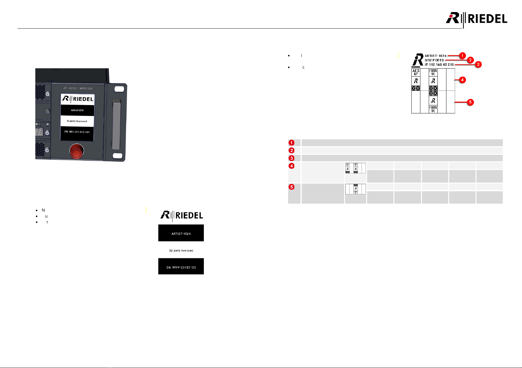
The frame design is rounded off by an e-paper display that provides configuration and licensing
information, even when powered off . Artist-1024 also offers flexible mounting options: The frame can be
mounted with an off set of 0.25, 50 or 75mm and can be rotated in the rack. If required, the ventilation can
be reversed to provide efficient cooling in any situation.
Artist-1024’s UIC concept and its versatile licensing scheme give you unprecedented flexibility, scalability,
and capability. With the ability to move ports between subscriber cards and flexibly assign connectivity
types as needed, you can easily customize individual nodes, and the entire system, to fit the needs of your
specific application. With Artist-1024 you get more than just full IP standards compliance and massive port
densities. What you get is the full power of the sophisticated Artist intercom ecosystem, a versatile and
future-proof solution that continues to evolve with industry developments and standards. With Riedel, you
have a partner on your IP journey who is committed to push the boundaries of innovation and is
passionate about shaping the future of production communications.
ST2022-7
ST2022-7
RSP-2318
RSP-1232HL
SMPTE 2110
NETWORK
SYNC DOMAIN A
SYNC DOMAIN B SYNC DOMAIN C
2110-30 (AES67)
2110-31 (AES3)
VoIP
MADI
DANTE
AVB
AES3
Analog
GPIO
2110-30 (AES67)
MADI
IP Layer 3
ARTIST Fiber
ST2022-7
13/03-0112
(AES67/AES3), MADI
NSA-002A
NSA-001D
RSP-2318
RSP-1232HL
ARTIST-1024
ARTIST-64
ARTIST-128
ARTIST-64
ARTIST-32
BOLERO
ARTIST-1024
NSA- 002A
IN1 IN2 IN3 IN4 OUT1 OUT 2 OUT3 OUT4
RCP-1112
figure 2: system overview (example)

9
Artist-1024 User Manual V8.4
10-005HB01AA-D00
2 Artist-1024 - Node
The Artist-1024 node incorporates the display and is shipped with two redundant power supplies and one
fan module with two high quality fans. Furthermore two front and one rear filter are part of the delivery
scope. All components are hot pluggable.
One Artist-1024 frame has slots for:
·
Front Bays
o8 Subscriber Interface Cards (SIC)
o2 Network Interface Cards (NIC; one primary PNIC and one secondary SNIC)
·
Rear Bays
o4 bays for future use
The possible capacities are:
·
8 ... 128 Ports per SIC
·
16 ... 1024 Ports per Frame
The Artist-1024 node is compatible to Artist-32/64/128 frames and can be integrated in present setups.
The management of the system is done in the Director configuration software. The frame must be
connected via the configuration ports (RJ45) of one of the ten UIC-128 cards.
The following chapters describe the basic components of the Artist-1024 system.
2.1 Frame (MFR-1024)
figure 3: Artist-1024 (front view)
figure 4: Artist-1024 (rear view)
front view
Position
SIC
NIC
Card type
Bay 1
ü
–
UIC-128
Bay 2
ü
–
Bay 3
–
ü
(primary > PNIC)
Bay 4
ü
–
Bay 5
ü
–
Bay 6
ü
–
Bay 7
ü
–
Bay 8
–
ü
(secondary > SNIC)
Bay 9
ü
–
Bay 10
ü
–
Filter (top/bottom)
FRF-1024
Display with rotary encoder
Display unit
rear view
Position
Card type
Bay A
future use
Bay B
Bay C
Bay D
Power Supplies (top/bottom)
PSU-1024
Fan module
FAN-1024
Filter
RRF-1024
The display is fixed to the frame and can be replaced by qualified Riedel service personnel only.
Caution
!
Please keep the Artist-1024 frame always closed to prevent the hardware from overheating.
Cover unused slots on the front and rear side with blind plates.

10
Artist-1024 User Manual V8.4
10-005HB01AA-D00
2.1.1 Info Display
The display shows system and license information of the Artist-1024 node. As the display uses e-paper
technology, this information is visible in the on and off state.
figure 5: info display
2.1.2 Display Content
Following status information is displayed when the power is off:
·
Name of the Artist-1024 node
·
Number of licensed ports
·
Serial number of the Artist-1024 node
figure 6: info display (node not powered)
If the Artist-1024 is connected to mains voltage, the default view is displayed:
·
Basic configuration information is shown to equip
the frame with the correct UICs and SFPs.
·
The currently selected slot position is indicated by
a bar above/below the corresponding position.
figure 7: info display (main view)
Name of the Artist-1024 node
Number of configured/licensed ports
IP address of the configuration port of the primary NIC (PNIC, bay 3)
Example of the
status info of the
upper slots
Bay: 1
Bay: 2
Bay: 3
Bay: 4
Bay: 5
AES67-SIC
SIC (not
equiped)
PNIC
(primary)
SIC (not
equiped)
SIC (not
equiped)
Example of the
status info of the
lower slots
Bay: 6
Bay: 7
Bay: 8
Bay: 9
Bay: 10
SIC (not
equiped)
SIC (not
equiped)
SNIC
(secondary)
SIC (not
equiped)
SIC (not
equiped)

11
Artist-1024 User Manual V8.4
10-005HB01AA-D00
SIC (Status Info)
Transport Type
Number of ports configured/assigned
in Director
Slot position of the respective card in
the Artist-1024 node
Artist ID of the node
IP-address/netmask of the
configuration port
NIC (Status Info)
Transport Type
Network interface active / standby
Slot position of the respective card in
the Artist-1024 node
Artist ID of the node
Long Name of the Artist-1024 node
IP address/netmask of the NIC
Gateway of the SIC (if active)
Serial number of the frame
2.1.3 Operation
In the Artist-1024 can be navigated through the display as follows:
Turning the rotary encoder
Select the next / previous slot
A horizontal line is displayed above/below the
currently selected slot position.
Pushing the rotary encoder
·
Enter selected slot / one layer down
Status information of the respective card is
displayed.
·
leave current slot / one layer back
The display jumps back to the main view.
The currently selected slot position is indicated by a bar above/below the corresponding position.

12
Artist-1024 User Manual V8.4
10-005HB01AA-D00
2.2 LED Wedge (WDG-1024)
The WDG-1024 card guides the air flow through the rack and thus ensures sufficient cooling of the
modules. The housing is made of transparent plastic, which is illuminated by RGB LEDs and indicates the
state of the corresponding card. Furthermore there is a sensor on the board that detects the
contamination of the air filter.
figure 8: WDG-1024
Sensor
Air guide
2.3 Front Filter (FRF-1024)
The top and bottom front filters protect the inside of the rack from dust and dirt.
figure 9: FRF-1024 (front view)
Caution
!
By default the MFR-1024 is equipped with air filters on the front side only.
Please observe the following instructions before operation:
·
There must be an air filter in the air inlet.
·
There must be no air filter in the air outlet.
·
Check the direction of the air flow after replacing a fan unit.
·
Fit or remove the air filters according to the direction of flow.
·
Only use original Riedel accessories.
·
The replacement of the front filter is described in the chapter 'Features in Detail > Replacing Front-
Filter'.
·
Reversing the airflow is described in the chapter 'Features in Detail > Reversing the Airflow'.

13
Artist-1024 User Manual V8.4
10-005HB01AA-D00
2.4 Power Supply (PSU-1024)
There are two power supplies in an Artist-1024 node: On the one hand, the energy is provided equally by
both power supply units. On the other hand, full redundancy can be guaranteed if both power supplies are
connected to different fuse circuits.
Both power supplies must be used to achieve the maximum device service life.
Danger
!
The power supplies must not be opened at any time.
figure 10: PSU-1024 (front view)
IEC
mains connector
·
100 - 240 VAC, 50 / 60 Hz
·
Cos phi 0,94
·
max. 225 W, 2.3 A, 768 BTU/h
·
12 VDC secondary voltage
Power
status LED
green
Both power supplies are in operation and power sharing is ok.
amber
This power supply is in operation but power sharing is faulty.
red
blinking
Power supply is short-circuited.
red
This power supply is not connected to mains voltage and is
supplied by the other power supply.
off
Power supply defective or no power supply is connected to mains
voltage.
Error
status LED
off
This power supply is ok.
amber
High current / high temperature detected.
red
Critical current / critical temperature detected.
red
blinking
Error of power sharing detected.
Synchronous flashing of both PSU LEDs indicates trouble-free operation between the PSUs.
2.5 Fan Unit (FAN-1024)
The Artist 1024 node has a fan unit with 2 high quality and quiet fans.
figure 11: FAN-1024 (front view)
The standard airflow for cooling the Artist-1024 flows horizontally from front to rear.
figure 12: Artist-1024 air flow
Caution
!
By default the MFR-1024 is equipped with air filters on the front side only.
Please observe the following instructions before operation:
·
There must be an air filter in the air inlet.
·
There must be no air filter in the air outlet.
·
Check the direction of the air flow after replacing a fan unit.
·
Fit or remove the air filters according to the direction of flow.
·
Only use original Riedel accessories.
·
The replacement of the rear filter is described in the chapter 'Features in Detail > Replacing Rear-Filter'.
·
Reversing the airflow is described in the chapter 'Features in Detail > Reversing the Airflow'.

14
Artist-1024 User Manual V8.4
10-005HB01AA-D00
2.6 Technical Drawing
figure 13: Artist-1024 – technical drawing (front view)
figure 14: Artist-1024 – technical drawing (top view)
2.7 Installation Options
The Artist 1024 frame can be installed mechanically in various ways:
·
Front cabling
·
Rack cabling
·
Variable installation depth
By default the 19" mounting brackets are mounted so that the front of the frame faces towards the
operator. With this mounting option the cabling can be easily and quickly carried out on the front of the
frame and can also be changed again.
If the mounting brackets are mounted rotated by 180°, the front of the unit faces into the rack and allows
cabling from the rear of the rack. This is advantageous for permanent installations, as the cabling is
protected inside the rack and cannot be accidentally changed.
Regardless of the orientation of the frame, the mounting brackets can be mounted in four different
positions on the frame to achieve different installation depths from 0 to 75 mm.
figure 15: Artist-1024 installation options

15
Artist-1024 User Manual V8.4
10-005HB01AA-D00
2.8 Technical Specification (Frame)
Number of ports per frame
16 ... 1024
Number of ports per card
8 ... 128
Licensing
Virtual Artist Matrix (VAM) license which includes a defined
number of ports (16 to 1024) that can be freely distributed
across the node’s subscriber cards.
Display type
High-Contrast e-paper display
Power supply
Mains voltage
100 - 240 VAC
Frequency
50 / 60 Hz
Cos phi
0,94
Power consumption
max. 225 W / <770 BTU/h, max. 2.3 A
Dimensions (installing dimensions)
Width
19" / 483 mm (17.5" / 445 mm)
Height
2RU / 3.5" / 88 mm
Depth
404 mm / 15.9" (377 mm / 14.8")
Weight
(inc. 2× PSU-1024 and 1× FAN-1024)
6,3 kg
Operating Environment
Operating Temperature
0 … +45 °C / 32 ... 113 °F
Storage Temperature
-30 ... +80 °C / -22 ... 176 °F
Humidity
20 ... 90 % RH (non-condensing)
Max Altitude
3000 m AMSL / 10,000 ft AMSL
Product codes
Artist-1024
1010010
FRF-1024
6530050
PSU-1024
1010011
FAN-1024
1010012
RRF-1024
6530100

16
Artist-1024 User Manual V8.4
10-005HB01AA-D00
3 Artist-1024 - Cards
3.1 UIC-128
The function of the UIC-128 card is determined by the slot position and card configuration in the Artist-
1024 node.
Slot
Function
SFP
Capacity
SIC
Audio interface
to connect:
·
SMPTE ST 2110-30
(AES67 channels)
·
MADI channels
·
electrical
·
optical
·
128 channels each UIC-128
oAES67:
128 channels each SFP
oMADI:
64 channels each SFP
NIC
Network interface
to connect:
·
Artist-1024
·
Artist-32/64/128
See also
ð
NIC Redundancy
optical (Down-/Up-stream to the
next/previous frame)
·
1024 channels in an
Artist-1024 frame
UIC-128 in ...
·
AES67 mode supports SFPs with SGMII and 1000BaseX interface.
·
MADI mode supports SFPs with 1000BaseX interface.
·
Artist-Fiber mode supports SFPs with 1000BaseX interface.
In version 8.0, the configuration and IP address is stored on the respective card.
If a UIC-128 in an Artist-1024 node has to be replaced, the configuration and IP address must be
manually stored on the card to be replaced.
In version 8.3, the configuration is no longer stored on the card, but on the NIC of the frame.
Only the configuration IP address of the UIC is still stored on the card. When replacing the UIC as
SIC, only the IP address must therefore be saved on the card to be replaced.
3.1.1 Front Elements
figure 16: UIC-128 (front view)
UIC-128 as SIC
Slot Media 1
Connection of two AES67 or MADI SFPs.
Two different formats cannot be used simultaneously.
Slot Media 2
USB Type-C (reserved for future use)
Configuration port (RJ45)
·
Management port to configure the Artist 1024 frame/network.
·
Configuration is done via the Director configuration software.
UIC-128 as NIC
Downstream (link output)
·
The downstream port is connected to the upstream port of the next Artist frame in
the Artist ring.
·
If a second UIC-128 is used in the Artist 1024 frame, this port is connected to the
upstream port of the second UIC-128.
Upstream (link input)
·
The upstream port is connected to the downstream port of the previous Artist frame
in the Artist ring.
·
If a second UIC-128 is used in the Artist 1024 frame, this port is connected to the
downstream port of the second UIC-128.
USB Type-C
·
License management
Configuration port (RJ45)
·
Management port to configure the Artist 1024 frame/network.
·
Configuration is done via the Director configuration software.

17
Artist-1024 User Manual V8.4
10-005HB01AA-D00
3.1.2 Status LEDs
figure 17: UIC-128 (status LEDs)
State
green
OK
amber
Warning
red
Error Level 1
red blinking
Error Level 2
Downstream- /
Upstream-
Quality
green
Link quality OK
amber
Link quality critical
red
Link quality poor
off
No connection
Downstream- /
Upstream-
Link
blue
Link OK
amber
Link OK, card is not Master
red
SFP malfunction
off
No connection
USB
reserved for future use
Ethernet
Activity
amber blinking
Activity
off
inactive
Ethernet
Link
green
1 Gbit/s connection OK
amber
10/100 Mbit/s connection OK
off
no connection
Operation
blue
Voltage OK
green fading in/out
Normal operation
off
No Voltage
3.1.3 Port Types
The table shows in which card configuration which port types are available in Director.
Port selection
Card
configuration
Port/Panel type
AES67-SIC
MADI-SIC
1200 series
RSP-1232HL
ü
–
RSP-1216HL
ü
–
ESP-1216HL
–
–
2300 series*
RSP-2318 (BASIC, PLUS, PRO)
ü
–
DSP-2312 (BASIC, PLUS)
ü
–
4-Wire
4-Wire (In and Out)
–
ü
4-Wire split (separated In and Out)
–
ü
Miscellaneous*
AES67 Trunkline
ü
–
Bolero Wireless Beltpack
ü
–
AES67 4-Wire
AES67 Input
ü
–
AES67 Output
ü
–
AES67 split (separated In and Out)
ü
–
4-Wire (In and Out)
ü
–
*
Not for redundant streams 2022-7.
3.1.4 Technical Specifications
Type
Product Code
Weight
Power Consumption
(typ./max.)
Voltage
UIC-128
1020100
280 g
13 W / 44 BTU/h
typ.
12 VDC
20 W / 68 BTU/h
max.
The UIC-128 uses a temperature compensated oscillator (TCXO) in AES67 SIC mode with an accuracy
of ±0.5 ppm. This is compatible with the media profile in master and slave mode.

18
Artist-1024 User Manual V8.4
10-005HB01AA-D00
4 Features in Detail
4.1 NIC Redundancy
The NICs in Bay 3 and Bay 8 are now fully synchronized and redundant.
For example, if another NIC is inserted in Bay 8 (secondary NIC > SNIC), the NIC in Bay 3 (primary NIC >
PNIC) remains active. The new SNIC is set into standby mode and the current Artist configuration is copied
into the new inserted SNIC. Also, the Artist ID and IP address are taken from the PNIC, whereby the IP
address of the SNIC is increased by '+1' to get an odd IP address. If the firmware on this SNIC is outdated
(firmware without final NIC redundancy support), it will be updated automatically.
In case of a failure of the active NIC (in this case the PNIC in Bay 3), the standby NIC (in this case the SNIC in
Bay 8) takes over the function and becomes the active NIC. The IP address is taken from the previously
active PNIC (even IP address) and the card becomes the ring clock master. The new NIC remains active until
it fails due to an error. The system will not switch the original PNIC back to active when it becomes available
again.
Executing the following steps describes the switching logic of the NIC redundancy.
Step
Action
PNIC
(Bay 3)
SNIC
(Bay 8)
Initial Configuration
active
standby
1
unplug SNIC (failing SNIC)
active
–
2
plug SNIC (SNIC ok)
active
standby
3
reboot Artist-1024 frame
active
standby
4
unplug PNIC (failing PNIC)
–
active
5
plug PNIC (PNIC ok)
standby
active
6
reboot Artist-1024 frame
standby
active
7
unplug SNIC (failing SNIC)
active
–
4.2 Replacing Front-Filter
The two air filters are located in the fan grilles on the front.
Follow the steps below to replace the air filters:
Ø
Loosen the four screws and remove the two fan grilles.
Ø
Then pull the air filters out of the fan grilles.
Ø
Insert the new/cleaned air filters into the fan grilles.
Ø
Carefully insert the fan grilles into the frame and screw them back in place.
figure 18: replacing front filter

19
Artist-1024 User Manual V8.4
10-005HB01AA-D00
4.3 Replacing Rear-Filter
The rear filter is located at the rear of the fan unit.
Follow these steps to replace the rear filter:
Ø
Loosen the four screws and remove the fan grille.
Ø
Then pull the air filter sideways out of the fan grille.
Ø
Insert the new/cleaned air filter into the fan grille.
Ø
Carefully insert the fan grille into the fan unit and tighten it again.
figure 19: replacing rear filter
4.4 Reversing the Airflow
If necessary, the direction of the air flow can be reversed by turning the fan block.
Carry out the following steps:
Ø
Loosen the 4 knurled screws of the fan unit.
Ø
Pull the fan unit out of the rack by loosening the
knurled screws.
Ø
Remove the two Torx screws from the fan block
using a T20 screwdriver.

20
Artist-1024 User Manual V8.4
10-005HB01AA-D00
Ø
Carefully pull the fan block upwards from the
circuit board.
Ø
Turn the fan block 180° and carefully insert it
back onto the circuit board.
Ø
Fasten the fan block with the two Torx screws.
Ø
Carefully slide the fan unit into the subrack.
Ø
Fasten the fan unit with the 4 knurled screws.
Ø
Fit or remove the air filters according to the direction of flow.
The air filter must only be located at the air inlet:
Air Flow Direction
FRF-1024
(Front-Filter)
RRF-1024
(Rear-Filter)
standard
from front to back
inverted
from back to front
Table of contents
Other Riedel Intercom System manuals

Riedel
Riedel PUNQTUM Q210 P User manual

Riedel
Riedel Bolero 3.1 User manual

Riedel
Riedel ASL Intercom PS 279 User manual

Riedel
Riedel Acrobat WB-2 User manual

Riedel
Riedel Punqtum Q110 User manual

Riedel
Riedel Bolero User manual

Riedel
Riedel Bolero Beltpack User manual

Riedel
Riedel Performer CR-4 User manual

Riedel
Riedel Punqtum Q Series User manual

Riedel
Riedel Punqtum Q Series User manual