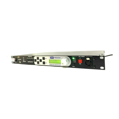
HME PRO850 User manual

HME# 400545
Rev — 4/26/04
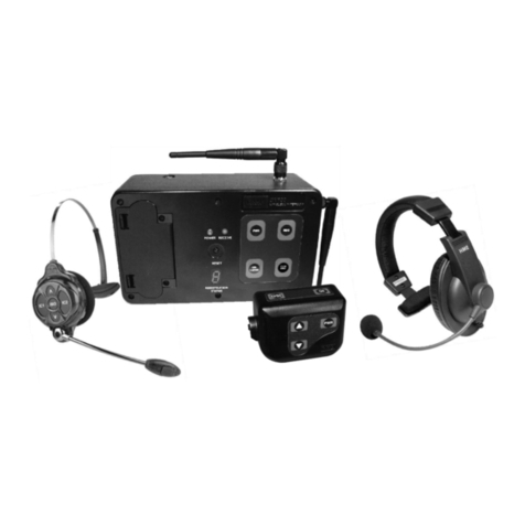
PRO850
Wireless Intercom
Quick Start Guide

Table of Contents
SECTION 1. INTRODUCTION ....................................................................................................................1
EQUIPMENT CONTROLS AND CONNECTORS..........................................................................................2
Base Station Front Panel.................................................................................................................................2
Base Station Rear Panel..................................................................................................................................2
Beltpac Top Panel...........................................................................................................................................3
Beltpac Bottom Panel.....................................................................................................................................3
SECTION 2. EQUIPMENT SETUP..............................................................................................................4
BASE STATION SETUP...................................................................................................................................4
BELTPAC SETUP.............................................................................................................................................4
SECTION 3. PRO850 CONFIGURATION..................................................................................................5
RESTORING FACTORY DEFAULT SETTINGS ...........................................................................................5
BASE STATION CONFIGURATION..............................................................................................................6
BELTPAC CONFIGURATION.........................................................................................................................8
SECTION 4. PRO850 OPERATION.............................................................................................................9
BELTPAC OPERATION...................................................................................................................................9
Controls, Indicators, and Buttons ...................................................................................................................9
Beltpac Audio Connectors and Mic Gain Adjustment .................................................................................10
BASE STATION OPERATION ......................................................................................................................11
Front Panel Controls, Indicators and Connectors.........................................................................................11
© 2004 HM Electronics, Inc.
The HME logo and product names are registered trademarks of HM Electronics, Inc. All rights reserved.
Illustrations in this publication are approximate representations of the actual
equipment, and may not be exactly as the equipment appears.
HM Electronics, Inc. is not responsible for equipment malfunctions due to
erroneous translation of its publications from their original English version.

1
PRO850 equipment operates in the UHF band from 470 MHz to 740 Hz in 18 MHz subsets. Transmitters and
receivers operate in different, non-adjacent 18 MHz bands. Synthesized frequencies can be selected in 25 kHz
increments over each 18 MHz band, for 720 transmit and 720 different receive frequencies.
This guide will take you through the steps necessary to quickly set up a stand-alone PRO850 system and four
Beltpacs. Once set up, you will be able to operate the system using the default Beltpac settings on a set of
preprogrammed frequencies. Then you can connect the PRO850 base station to a wired intercom system.
This guide assumes that you do not have any saved configuration that you wish to use. It will guide you through
restoring the factory default settings and beginning operation from that point. If this is not what you wish to do,
please refer to your PRO850 Operating Instructions manual.
SECTION 1. INTRODUCTION

2
1 2 3 4 5 6 7 8 9 10 11 12 13 14 15
EQUIPMENT CONTROLS AND CONNECTORS
Refer to the figures below and on the next page for the locations of controls and connectors.
Base Station Front Panel
1. POWER switch (with LED power indicator)
2. BELTPAC CONFIGuration connector
(RJ10 telephone handset cable connector)
3. WIRED STATUS lights
CH1 = Channel 1 intercom status
CH2 = Channel 2 intercom status
AUX = ISO+ mode
4. RECEIVER QUICK MENU buttons
5. RECEIVER STATUS lights
6. Arrow buttons (move curser around on menu)
7. ENTER button (selects function or setting)
8. CANCEL button
(backs out of menus or cancels operation)
9. Display screen
10. Multi-function knob (headset volume control;
adjustment for specific menu selections)
11. Local headset function lights
12. Local headset function select switch
13. Local headset TALK indicator light
14. Local headset TALK switch
15. Local headset connector
Base Station Rear Panel
1. Receive antenna connector
2. USB type-B computer connector
3. 9-pin RS-232 computer connector
4. RS-422 connector
(for connecting two or more bases together)
5. Channel 1 null adjustment
6. Channel 1 2-wire intercom connector
7. Clear-Com/RTS TW select button
8. Channel 2 2-wire intercom connector
9. Channel 2 null adjustment
10. Channel 1 RJ45 4-wire intercom connector
11. Channel 2 RJ45 4-wire intercom connector
12. Auxiliary input connector
(accepts XLR plug or standard phone plug)
13. Auxiliary output connector
14. Paging output connector
15. 12-14VDC power jack
16. Page relay connector
17. Alert relay connector
18. Transmit antenna connector
19. Grounding screw
1 2 3 4 5 6 7 8 9 10 11 12 13 14 15 16 17 18 19

3
1 2 3 4 5 6 7 8 9 10 11 12
Beltpac Top Panel
1. Master power/volume control
2. “A” button
3. Power and battery condition indicator
4. “C” button
5. “A” function indicator
6. “C” function indicator
7. “D” function indicator
8. “B” function indicator
9. “D” button
10. Transmit indicator
11. “B” button
12. Auxiliary volume control
Beltpac Bottom Panel
1. Headset connector
2. Transmit antenna connector
3. Remote configuration connector
4. Battery compartment cover thumb grip
5. Microphone gain adjustment
6. Auxiliary input connector
7. Receive antenna connector
1 2 3 4 5 6 7

4
BASE STATION SETUP
The steps below will guide you through connecting the antennas and the power supply to the base station. Refer
to the Base Station Front and Rear Panel illustrations on page 2.
1. RECEIVE Antenna — Connect the receiver antenna to this connector (#1 on rear panel). The color band
(if present) around the antenna should match the color dot (if present) near the connector on the base.
2. 12-14VDC Power — Connect the cable from the power supply to this power socket (#15 on rear panel).
3. TRANSMIT Antenna — Connect the transmit antenna to this connector (#18 on rear panel). The color band
(if present) around the antenna should match the color dot (if present) near the connector on the base.
4. AC Power –– Connect the appropriate power cord to the power supply and plug it into an electrical outlet.
The power supply will automatically adjust for different line voltages and frequencies. Turn on the base
station power by pressing the upper part of the power switch (#1 on front panel). The red light in the power
switch and the display screen should light. After about 5 seconds, the HME logo should appear on the
display screen. After another second or two, the logo will fade away and a menu will appear.
BELTPAC SETUP
Prepare each of the Beltpacs for operation as described in the steps below. Refer to the Beltpac Top and Bottom
Panel illustrations on page 3.
1. RECEIVE Antenna — Screw the receiver antenna into the receive antenna connector (#7 on bottom
panel) and tighten it with your fingers. The color band (if present) around the antenna should match the
color dot (if present) near the connector on the Beltpac.
2. TRANSMIT Antenna — Screw the transmitter antenna into the transmit antenna connector (#2 on bottom
panel) and tighten it with your fingers. The color band (if present) around the antenna should match the
color dot (if present) near the connector on the base.
3. Batteries –– Turn the power switch off by rotating the Master power/volume control (#1 on top panel)
fully counterclockwise until the switch clicks. Install six fresh alkaline or NiMH AA batteries in each
Beltpac. See the detailed instructions below if you are uncertain how to install batteries.
1. Battery Compartment Cover
2. Battery Cover Thumb Grip
To change batteries:
Place your thumb on the battery compartment
cover thumb grip and pull back on the battery
compartment cover to open the battery
compartment. Carefully flip the cover up and slide
it to the back of the opening and push it slightly
downward to release the battery sled into your hand.
Install six fresh 1.5V AA batteries in the sled and
reinstall the sled in the Beltpac.
Carefully slide the battery compartment cover back
over the compartment until it latches.
3. CONFIGURATION Connection –– Plug one end of the configuration cable (coiled telephone handset
cable) into the configuration connector on the bottom of the Beltpac (#3 on bottom panel). Plug the other
end into the configuration connector on the front of the base station (#2 on base station front panel).
SECTION 2. EQUIPMENT SETUP
1 2
5
Now that everything is connected and ready, you can begin the configuration process. Most factory default
settings will not be changed. However, a few settings must be changed to make the system operational. This is
because the base is shipped with the receivers disabled and all transmitters turned off.
This guide assumes that you wish to start from the factory default configuration settings. You will learn to
restore the factory default settings as part of this process. If that is not what you want to do, please refer to your
PRO850 Operating Instructions manual.
RESTORING FACTORY DEFAULT SETTINGS
CAUTION: These steps will restore the base station to its factory default settings. Any settings previously
saved in the base station will be lost.
Refer to the base station illustrations on page 2 as needed.
1. Turn on the base station power, if it is not already on.
2. With the menus displayed, press the right or left arrow button as needed on the base station (#6 on front
panel) until the Config menu is displayed.
3. Press the down arrow button repeatedly until Files is highlighted as shown below. Then press the ENTER
button (#7 on front panel). The System Setup menu should appear.
4. Press the down arrow button to highlight Load Settings and press ENTER. The Load Settings from File
window will appear.
5. Press and hold the down arrow button until Def appears in the lower portion of the file window. Then press
ENTER. Def will now appear highlighted in the upper part of the file window.
6. Press the right arrow button once to move the cursor (small triangle) over to the check box beside the word
Load.
7. Press ENTER to begin the process. After the default settings have been loaded, an attention window will
appear indicating “Settings Defaulted.” Press CANCEL to clear the window. You are now ready to
configure the system.
SECTION 3. PRO850 CONFIGURATION

6
BASE STATION CONFIGURATION
The following steps will guide you through a frequency scan and configuration of the base transmitters and
receivers. The frequency scan will identify the best of the pre-programmed frequencies available at your
location. If none of these frequencies work for your application, you will need to refer to the Operating
Instructions for setting user frequencies.
1. Turn on the Beltpac that is connected to the base station configuration port by rotating the master volume
control clockwise. The A and PWR/BATT indicators should both illuminate green.
2. Use the right or left arrow buttons on the base station to highlight the Config menu. Then use the up arrow
key if necessary to highlight Base as shown below.
3. Press ENTER and the Base Setup menu will appear. Then use the down arrow button to highlight Scan as
shown.
4. Press ENTER to display the Scan Frequencies window.
5. To begin the scan, press ENTER. An attention window will appear. Since you have not made any other
configuration changes, you do not need to save your settings. Press CANCEL to clear the window. Press
ENTER again to begin scanning.
6. The scan will require approximately 30 seconds (different hardware configurations may require more time).
During this time, Processing will be displayed in the scan window. When the scan is finished, Success will
be displayed in the window and the base receivers and transmitters will be configured for the appropriate
frequencies. These frequencies will also be loaded into the Beltpac settings memory in the base. Press
CANCEL once to exit the scan mode and return to the Base Setup menu.
7. Use the up arrow button to highlight TX and press ENTER. The Base TX Setup menu will appear with TX
Power highlighted.
8. Press ENTER to open the Base TX Power window.

7
9. Press the right arrow button to move the cursor to the power select list. Use the up and down arrow buttons to
select the desired transmit power for TX1. Choose the lowest power level that gives sufficient range. If you
are unsure, choose 100 mW to start. You can increase or decrease it later. When you have selected a power
level, press ENTER. The selected power level will now be highlighted at the top of the power window.
10. Press the right arrow button to move the cursor to the mode selection. If the radio button (small circle) next
to Off is black, press the down arrow to move the cursor down to the radio button next to On. Then press
ENTER. The black circle will move down and the transmitter will come on.
11. Press the right arrow button again. The cursor will return to the transmitter selection window. Press the
down arrow button to select Tx2. Then press ENTER.
12. Repeat steps 9 and 10 for the second transmitter (Tx2). Then press CANCEL to close the Base TX Power
window. If you only require one channel operation, you can leave Tx2 off.
13. Next, you must enable the receivers. Press Receiver Quick Menu button 1 (#4 on the illustration). This will
cause the Base RX Setting window to appear.
14. Press the left arrow button once to move the cursor to the mode radio buttons. If the On radio button is
black, skip to the next step. If the Off radio button is black, press the down arrow button to move the cursor
down to On and press ENTER. The On radio button will turn black and receiver 1 will be enabled.
15. Press the next Receiver Quick Menu button (2) and repeat step 14 to enable receiver 2. Then do the same
for receivers 3 and 4.
16. Press CANCEL to close the Base RX Setting window and return to the Config menu.
17. The next step is to save these settings. Use the down arrow button to highlight Files. Then press ENTER to
open the System Setup menu.
NOTE: Settings must be saved before the power is shut down or they will be lost. This is true any time you
change base settings. Be sure to save them.
18. Be sure that Save Settings is highlighted (use the up arrow button if necessary) and press ENTER. The
Save Settings to File window will appear. File 2 should be highlighted as shown.
19. Press the right arrow button to move the cursor (small triangle) to the check box next to the word Save.
Then press ENTER. It will take a few seconds to save the settings. When the settings are saved, Success
will be displayed in the window.
20. Press the CANCEL button to close the Base RX Setup window. Press the CANCEL button a second time
to return to the Config menu.
The base is now configured and ready to use. Next you must upload these configuration settings to each Beltpac.

8
BELTPAC CONFIGURATION
These steps will guide you through the process of uploading configuration settings to the Beltpacs. Each
Beltpac has its own set of configuration settings stored in the base. The upload process transfers these settings
to the Beltpac and saves them there.
1. Be sure that there is a Beltpac connected to the base configuration connector and that its power is on.
CAUTION: Do not press any Beltpac buttons until after Step 7, or you will have to turn off the Beltpac power
and restart at Step 1.
2. Press the up or down arrow button as needed to highlight Beltpac as shown below.
3. Press ENTER to open the Beltpac Setup menu. Use the down arrow button to scroll down the list until
Upload is highlighted.
4. Press ENTER to open the BP Settings Upload window. We will be starting with BP1 so there is no need to
select the Beltpac at this time.
5. Press the right arrow button once to move the cursor to the Upload check box.
6. Press ENTER to start the upload. If the Beltpac is properly connected, Success will appear in the window
after a few seconds. If Dev Not Pres appears, the configuration cable is not properly connected or the
Beltpac is not on.
7. Turn off the Beltpac and disconnect it from the configuration cable. Label it so that you will know which
one it is.
8. Connect another Beltpac to the configuration cable and turn it on.
9. Press the right or left arrow button to position the cursor next to the Beltpac selection list. Then press the
down arrow once to select BP2.
10. Press ENTER and BP2 will be highlighted.
11. Repeat steps 5, 6, and 7 for this Beltpac.
12. Repeat steps 10 and 11 for the remaining Beltpacs.
13. Press CANCEL twice to return to the Config menu.
Congratulations! Your PRO850 system is now configured and ready to go.

9
This section describes how to operate your newly configured PRO850 system, assuming the factory default
settings. If you used other existing settings rather than factory defaults, you will need to refer to the PRO850
Operating Instructions for information regarding those settings.
BELTPAC OPERATION
Refer to the figures below for the functions of the various controls in the default configuration. The functions of
the buttons are configurable and may be different if you are not using default settings.
Controls, Indicators, and Buttons
1. Master On/Off Volume Control
Turns Beltpac on and off.
Controls volume levels and beep intensity.
Press and hold control button in to mute primary receiver input.
2. PWR/BATT Indicator
Remains lit when power is on.
Green = good batteries
Amber = low batteries
Red = nearly dead batteries
3. Transmit Indicator
On red when Beltpac is transmitting. Default mode is PTE – transmitter on continuously
4. A Button (Talk Channel 1)
Press and release button in less than one second to lock on talk on channel 1. Only Beltpacs listening to
channel 1 will hear you.
Press and hold for momentary function, to remain on only while button is held.
This button only works if the B indicator is not red.
5. A Channel Indicator (Channel 1)
Green while listening to channel 1 and red while talking on channel 1.
6. B Button (Talk Channel 2)
Press and release button in less than one second to lock on talk on channel 2. Only Beltpacs listening to
channel 2 will hear you.
Press and hold for momentary function, to remain on only while button is held.
This button only works if the A indicator is not red.
SECTION 4. PRO850 OPERATION
1
1
4
8
12
10
6
9
2 3
11
5
7

10
7. B Channel Indicator (Channel 2)
Green while listening to channel 2 and red when talking on channel 2.
8. C Button (Talk ISO)
Press and hold to talk to all Beltpac users independent of their channel selection.
9. C Indicator (ISO)
Lights red while talking on ISO.
10. D Button (Talk Page)
Press and hold to talk on the paging output of the base. All Beltpacs will hear the transmission as well. The
base station paging relay will energize while the button is held.
11. D Indicator (Page)
Lights red while paging.
12. Auxiliary Volume Control
Controls mix level of Beltpac auxiliary input (on bottom of Beltpac) or the level from a second (optional)
receiver, if installed.
Press and hold control button in to mute auxiliary input.
Holding the C and D buttons while turning the Beltpac power on will disable all indicator LED’s until the next
time the Beltpac power is turned off and on again.
Beltpac Audio Connectors and Mic Gain Adjustment
1. Headset Connector
XLR type connector. Automatically adjusts for electret or dynamic microphones.
2. Headset Microphone Gain Adjustment
Adjusts headset microphone gain ±10dB.
3. Auxiliary Input Connector
1/8 inch (3.5 mm) jack receptacle for line level monaural audio source.
If the Beltpac includes a second (optional) receiver, plugging into this location will disconnect the audio
from the second receiver and connect the audio from the auxiliary input device in its place.
1
2 3

11
BASE STATION OPERATION
Refer to the figure below for the functions of the various controls in the default configuration. There may be
differences if you are not using the factory default settings.
Front Panel Controls, Indicators and Connectors
1. Receiver Quick Menu Buttons
Press any of these buttons to access the settings for that receiver. When the button is pressed, the control
knob (#3) becomes the squelch control for that receiver. Press the down arrow once to select Audio Level.
Then the knob adjusts the receiver audio gain.
2. Receiver Status Indicators
These indicate the receiver status at a glance: dark when no signal received or the receiver is disabled, red
when receiving a carrier or the squelch is open, amber (green & red) when receiving status from a Beltpac,
and green when a Beltpac user is talking. If an indicator is blinking while a Beltpac is transmitting, it
indicates the Beltpac batteries are low.
3. Control Knob
Use this knob to adjust receiver or other levels, and as local headset volume control.
4. Local Headset Select Button and Indicators
These are used to select the talk channel(s) for the local headset. Press to cycle through CH1, CH2, CH1 &
CH2, and ISO.
5. Local Headset Talk Button and Indicator
Press and release quickly to latch on the local headset talk function. Press and hold for momentary talk
operation. The indicator lights red while talk is active.
6. Local Headset Connector
Connect a headset for use at the base. Automatically adjusts for electret or dynamic microphone.
1 2 3 4 5 6
Other manuals for PRO850
1
Table of contents
Other HME Intercom System manuals

HME
HME Clear-Com DX410 EU User manual

HME
HME Clear-Com EQUIP G30238-3A1 User manual

HME
HME System 6001 Manual

HME
HME DX200 User manual

HME
HME Clear-ComMS-704 User manual

HME
HME DX121 EU User manual

HME
HME Clear-Com HelixNet Partyline User manual

HME
HME PRO850 User manual

HME
HME DX100 User manual

HME
HME Clear-Com EQUIP G30238-3A1 User manual

HME
HME DX200 User manual

HME
HME DX100 User manual

HME
HME Clear-Com ARCADIA Series User manual

HME
HME DX121 User manual

HME
HME Clear-Com HelixNet Partyline User manual

HME
HME DX200 User manual

HME
HME DX100 User manual

HME
HME DX100 User manual

HME
HME Clear-Com Tempest 2400 User manual

HME
HME Clear-Com Arcadia Central Station User manual