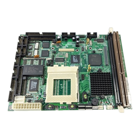
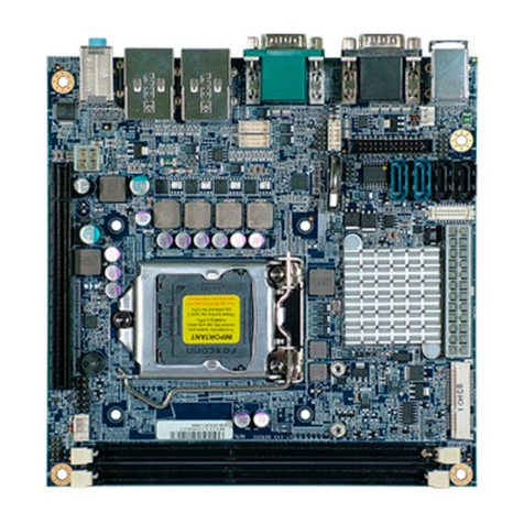
protech ProX-1650 User manual

USER’S
MANUAL
ProX-1650

Copyright Notice
ProX-1650 Socket 370
Main Board
With VGA / SOUND / Dual LAN
OPERATION MANUAL
COPYRIGHT NOTICE
This operation manual is meant to assist both Embedded Computer
manufacturers and end users in installing and setting up the system. The
information contained in this document is subject to change without any
prior notice.
This manual is copyrighted July 6, 2001. (Revised Edition: Nov. 21, 2001)
You may not reproduce or transmit in any form or by any means,
electronic, or mechanical, including photocopying and recording.
ACKNOWLEDGEMENTS
All trademarks and registered trademarks mentioned herein are the property
of their respective owners.

Contents
TABLE OF CONTENTS
CHAPTER 1 INTRODUCTION
1-1 About This Manual ....................................................... 1-2
1-2 System Specifications ................................................... 1-3
1-3 Safety Precautions ......................................................... 1-6
CHAPTER 2 HARDWARE CONFIGURATION
2-1 Jumper & Connector Quick Reference Table ............... 2-2
2-2 Component Locations ................................................... 2-3
2-3 How to Set the Jumpers ................................................ 2-4
2-4 COM Port Connector ………………………………… 2-6
2-5 RS232/422/485 (COM2) Selection ............................... 2-8
2-6 COM3 RI & Voltage Selection ………………………. 2-9
2-7 COM4 RI & Voltage Selection ………………………. 2-9
2-8 Solid-State Disk Socket ………………………………. 2-10
2-9 SSD Memory Mapping Selection ................................. 2-11
2-10 Keyboard Connector …………………………………. 2-12
2-11 PS/2 Mouse Connector ……………………………….. 2-12
2-12 Reset Connector ……………………………………… 2-13
2-13 External Speaker Connector ………………………….. 2-13
2-14 Hard Disk Drive LED Connector .................................. 2-14
2-15 Power LED & Keylock Connector ..........................…. 2-14
2-16 ATX Power Button …................................................... 2-15
2-17 IrDA Connector ……………....................................…. 2-15
2-18 ATX Power Connector ................................................. 2-16
2-19 VGA Connector ……………….................................... 2-17
2-20 Printer Connector …….................................................. 2-18
2-21 Universal Serial Bus Connector …................................ 2-20
2-22 LAN Connector ……………......................................... 2-21
2-23 LAN2 Led Indicator …………….................................. 2-22
2-24 LAN2 Enable/Disable Connector ................................. 2-22
2-25 Wake-on-modem Connector ......................................... 2-23
2-26 Reset/NMI/Clear Watchdog Selection .......................... 2-23
2-27 CPU Fan Connector .........…......................................... 2-24
2-28 System Fan Connector ………….................................. 2-24
2-29 Hard Disk Drive Connector .......................................... 2-25
Contents
2-30 Floppy Disk Drive Connector ....................................... 2-27
2-31 Line-Out Connector ............…...................................... 2-28
2-32 Line-In Connector …………......................................... 2-29
2-33 Microphone Connector ................................................. 2-29
2-34 CD Audio-In Connector ……………………………… 2-29
2-35 S-Video Out Connector ………………………………. 2-30
2-36 Composite Video Connector ……………………….. 2-30
2-37 TV-Out Address Setting ……………………………… 2-30
2-38 TV or DVI Selection …………………………………. 2-31
2-39 NTSC or PAL Selection ……………………………… 2-31
2-40 Panellink (DFP) Connector …………………………… 2-32
2-41 External Keyboard Connector ………………………... 2-33
2-42 Clear CMOS Data Selection ………………………….. 2-33
2-43 Memory Installation ...................................................... 2-34
CHAPTER 3 SOFTWARE UTILITIES
3-1 Introduction ................................................................... 3-2
3-2 VGA Driver Utility ....................................................... 3-2
3-3 Flash BIOS Update ....................................................... 3-3
3-4 LAN Driver Utility ….................................................... 3-5
3-5 Sound Driver Utility ………………………………….. 3-7
3-6 Watchdog Timer Configuration .................................... 3-8
CHAPTER 4 GREEN PC FUNCTION
4-1 Power Saving Block Diagram ....................................... 4-2
4-2 System Suspend Mode .................................................. 4-2
CHAPTER 5 AWARD BIOS SETUP
5-1 Introduction ................................................................... 5-2
5-2 Entering Setup ............................................................... 5-3
5-3 The Standard CMOS Features …….............................. 5-4
5-4 The Advanced BIOS Features …................................... 5-8
5-5 Advanced Chipset Feature ............................................ 5-11
5-6 Integrated Peripherals ……........................................... 5-14
5-7 Power Management Setup ............................................ 5-18

Contents
5-8 PNP/PCI Configuration …............................................. 5-21
5-9 PC Health Status ……................................................... 5-23
5-10 Frequency / Voltage Control …..................................... 5-24
5-11 Load Fail-Safe Defaults ................................................ 5-25
5-12 Load Optimized Defaults …..………………………… 5-25
5-13 Password Setting …………………………………… 5-26
5-14 Save & Exit Setup ......................................................... 5-27
5-15 Exit Without Saving ...................................................... 5-28
APPENDIX A EXPANSION BUS
ISA Bus Pin Assignment .......................................................... A-2
PCI Bus Pin Assignment …………………………………….. A-3
APPENDIX B TECHNICAL SUMMARY
Block Diagram ......................................................................... B-2
Interrupt Map ............................................................................ B-3
RTC (Standard) RAM Bank ..................................................... B-4
Timer & DMA Channels Map .................................................. B-5
I/O & Memory Map ................................................................. B-6
APPENDIX C TROUBLE SHOOTING
Trouble Shooting for Error Messages ...................................... C-2
Trouble Shooting for POST Codes .......................................... C-6

Page:1-1
INTRODUCTION
This chapter gives you the information for Prox-1650. It also
outlines the System specifications.
Section includes:
zAbout This Manual
zSystem Specifications
zSafety precautions
Experienced users can skip to chapter 2 on page 2-1
for a Quick Start.
CHAPTER
1

Chapter 1 Introduction
Page: 1-2 Prox-1650 USER
′
S MANUAL
1-1. ABOUT THIS MANUAL
Thank you for purchasing our Prox-1650 Socket 370 Mainboard enhanced
with VGA/Sound/Dual LAN, which is fully PC / AT compatible. The
Prox-1650 provides faster processing speed, greater expandability and can
handle more tasks than before. This manual is designed to assist you how
to install and set up the system. It contains five chapters. The user can
apply this manual for configuration according to the following chapters:
Chapter 1 Introduction
This chapter introduces you to the background of this manual, and the
specifications for this system. The final page of this chapter will indicate
how to avoid damaging this board.
Chapter 2 Hardware Configuration
This chapter outlines the component locations and their functions. In the
end of this chapter, you will learn how to set jumper and how to configure
this card to meet your own needs.
Chapter 3 Software Utilities
This chapter contains helpful information for proper installations of the
VGA utility, LAN utility, Sound utility, and Flash BIOS Update. It also
describes the Watchdog-timer configuration.
Chapter 4 Green PC Function
This chapter explains the Green PC functions concisely.
Chapter 5 Award BIOS Setup
This chapter indicates you how to set up the BIOS configurations.
Appendix A Expansion Bus
This Appendix introduces you the expansion bus for ISA BUS and PCI
BUS.
Appendix B Technical Summary
This section gives you the information about the Technical maps.
Appendix C Trouble Shooting
This section outlines the error messages and offers you the methods to
solve the problems.

Chapter 1 Introduction
Prox-1650 USER
′
S MANUAL Page: 1-3
1-2. SYSTEM SPECIFICATIONS
zCPU :
Intel® CeleronTM processors in 370-pin socket.
300A/333/366/400/433/466/500/533/566/600/633/667/700/733/766/800MHz.
Intel® Pentium® !!! processors in 370-pin socket.
500E/550E/600E/650/700/750/800/850MHz.
Auto detect voltage regulator.
Support FSB 66 / 100 MHz.
zMEMORY :
Up to 512MB SDRAM
Two 168pin DIMM sockets on board.
zCACHE :
Depended on CPU (128/256KB).
zREAL-TIME CLOCK :
256-byte battery backed CMOS RAM
Hardware implementation to indicate century roll-over.
zBIOS :
Award Flash BIOS for plug & play function.
Easy update 512KB flash EEPROM.
Support Green Function.
Support S/IO Setup.
zKEYBOARD CONNECTOR :
Mini DIN connector.
Supports for AT keyboard.
zMOUSE CONNECTOR :
Mini DIN connector.
Supports for PS/2 Mouse.
zDISK-ON-CHIPS SOCKET :
A 32-pin SSD socket.
Supports up to 288MB Disk-on-chips.

Chapter 1 Introduction
Page: 1-4 Prox-1650 USER
′
S MANUAL
zBUS SUPPORT :
Internal AGP for VGA
Internal PCI for IDE, LAN, and Sound
External 4 ISA Bus and 4 PCI Bus.
zDISPLAY :
Built-in GMCH, Support for CRT and PanelLink/TV-Out (optional).
Support 2D/3D engine.
Support a Dynamic Video Memory Technology (DVMT) which allows the
entire 3D rendering process to take place in system memory.
Onboard 15-pin connector, support for resolution on SVGA Monitor.
Onboard 20-pin connector, support for PanelLink (optional).
Onboard 2-pin for Composite Video Connector (optional).
Onboard 3-pin for S-video (optional).
zWATCHDOG :
I / O port 0443H to Enable watchdog.
I / O port 0441H to Disable watchdog.
Selectable for NMI or Reset function by jumper setting.
Time-out timing select 0 / 8 / 16 / 24 / 32 / 40 / 48 / 56 / 64 / 72 / 80 / 88 / 96 /
104 / 112 / 120 sec +/- 25%.
zIDE INTERFACE :
Two IDE port, support Ultra DMA-33/66/100.
2 Channel support 4 devices.
zFLOPPY DISK DRIVER INTERFACE :
Support up to two Floppy Disk Drives, 3.5" and 5.25" (360K / 720K / 1.2M /
1.44M / 2.88M).
zUSB CONNECTOR :
Two sets of USB connector.
Supports up to four USB ports.
zLAN ADAPTER :
Dual Port, Intel® 82559 & Intel® 82562 Fast Ethernet
10/100 Base-T PCI-BUS.
Support wake-on-LAN function.

Chapter 1 Introduction
Prox-1650 USER
′
S MANUAL Page: 1-5
zSERIAL PORT :
Four high speed 16550 Compatible UARTs with Send / Receive 16 Byte
FIFOs; COM1/3/4:RS-232; COM2:RS-232/422/485.
MIDI Compatible.
Programmable Baud Rate Generator.
zSOUND :
Enhanced Analog Device AD1881 (AC’97 Codec).
Fully Compliant AC’97 Analog I/O Component
16-Bit Stereo Full-Duplex Codec
Four Analog Line-level Stereo Inputs for Connection.
High Quality CD Input with Ground Sense
Stereo Line-Level Output
Interface: Line-In, Line-Out, Microphone, and CD Audio-In.
zHARDWARE MONITORING FUNCTION :
Monitor Voltage, CPU temperature, & Cooling fan.
zIRDA PORT :
5-pin Infrared port, support IrDA v1.0 SIR protocol
zPARALLEL PORT :
SPP / ECP / EPP Function.
2 port, Bi-directional parallel port.
zGREEN FUNCTION :
Software supported by BIOS setup.
zLED INDICATOR :
System power.
Hard Disk access.
LAN LED indicator.
zDMA CONTROLLER :
82C37 x 2
zDMA CHANNELS :
7

Chapter 1 Introduction
Page: 1-6 Prox-1650 USER
′
S MANUAL
zINTERRUPT CONTROLLERS :
82C59 x 2
zINTERRUPT LEVELS :
15
zOPERATING TEMPERATURE :
0 to 60°C.
zSYSTEM POWER REQUIREMENT :
DC Voltage: +5V, minimum +4.75V, maximum 5.25V.
DC Ampere: 15A.
DC Voltage: +12V, minimum +11.4V, maximum 12.6V.
DC Ampere: 500mA.
zBOARD DIMENSIONS :
305mm x 244mm
zBOARD NET WEIGHT :
0.71 Kgs.
1-3. SAFETY PRECAUTIONS
Follow the messages below to avoid your systems from damage:
1. Keep your system away from static electricity on all occasions.
2. Prevent electric shock. Don‘t touch any components of this card when the
card is power-on. Always disconnect power when the system is not in use.
3. Disconnect power when you change any hardware devices. For instance,
when you connect a jumper or install any cards, a surge of power may
damage the electronic components or the whole system.

Page 2-1
HARDWARE
CONFIGURATION
** QUICK START **
Helpful information describes the jumper & connector settings, and
component locations.
This section includes:
zJumper & Connector Quick Reference Table
zComponent Locations
zConfiguration and Jumper settings
zConnector‘s Pin Assignments
CHAPTER
2

Chapter 2 Hardware Configuration
Page: 2-2 Prox-1650 USER'S MANUAL
2-1. JUMPER & CONNECTOR QUICK REFERENCE TABLE
COM Connector ….................................……................
……………………………………….. COM1, COM2
COM3, COM4
RS232/422/485 (COM2) Selection ......................……... JP1
COM3 RI & Voltage Selection ………………………... JP8
COM4 RI & Voltage Selection ………………………... JP9
Solid-State Disk Socket .......................................……... SSD
SSD Memory Mapping Selection ........................……... JP6
Keyboard Connector ………………....................……... KB
PS/2 Mouse Connector ………………………………… MS
Reset Connector ...................................................…….. CN13
(21-22)
External Speaker Connector ……….………………….. CN13 (2,4,6,8)
Hard Disk Drive LED Connector ........................……… CN13 (10,12,14,16)
Power LED & KeyLock Connector ….................……... CN13 (1,3,5,7,9)
ATX Power Button …………..………………………… CN13 (18,20)
IRDA Connector ……………………………………….. CN13
(11,13,15,17,19)
ATX Power Connector ………………………………… CN9
VGA CRT Connector ..........................................……... VGA
Printer Connector .................................................…….. PRT1, PRT2
Universal Serial Bus Connector ...........................…….. USB1, USB2
LAN Connector ...........................................…………… LAN1, LAN2
LAN2 Led Indicator ….……………………………….. CN3
LAN Enable/Disable Selection ….……………………. JP2
Wake-On-Modem Connector ………………………….. CN6
Reset/NMI/Clear Watchdog Selection ……………….….. JP7
CPU Fan Connector .............................................…….. CN5
System Fan Connector ………………………………… CN4, CN12
Hard Disk Drive Connector .................................…….. IDE1, IDE2
Floppy Disk Drive Connector ..............................…….. FDD1
Line-Out Connector ..………………………………….. Line-Out
Line-In Connector ..……………………………..…….. Line-In
Microphone Connector ……………………………….. MIC
CD Audio-In Connector ….…………………………… CN1
S-Video Out Connector ……………………………….. CN10
Composite Video (AV) Connector ……………………. CN7
TV-Out Address Setting ….…………………………… JP3
TV or DVI Selection …………………………………... JP4 (1,3,5)
NTSC or PAL Selection ……………………………….. JP4 (2,4,6)
PanelLink (DFP) Connector ……..……………………. CN8
External Keyboard Connector …………………………. CN2
Clear CMOS Connector ……………………………….. JP5
Memory Installation .............................................……... DIMM1, DIMM2

Chapter 2 Hardware Configuration
Prox-1650 USER'S MANUAL Page: 2-3
2-2. COMPONENT LOCATIONS
LAN1
DIMM 2
DIMM 1
CPU
Socket 370
PRT1
VGA
IO
COM 2
Battery
82801
Intel
82815
Intel
USB1
MS
COM1
IDE2
COM 3
ISA IO
CN9
CN10
MIC
SSD
KB
PRT2
IDE1
Bridge
ISA1
FDD1
82559
Intel
LPC
COM 4
PCI4PCI3PCI2PCI1
ISA4ISA3ISA2
JP1
CN5
CN7
CN12
CN4
6
25
5
1
6
1
32
5
4
65
5
7
6
8
1243
10
3
2
4
1
1
7
2
11
8
91210
6
5
1
11
1
10
5
15 9
113
14
11 61
51 51
10 6 10 6
1
33
1
34
14 26
113
1
2
39
40
1
239
40
1
21
2
CN13
22
21
12
JP6
12
11
1
2
CN3
6
51
2
5
JP7
6
51
2
CN6
1
CN1
1
20
CN8
11
6
USB2
1
10 5
CN2
1
JP5
1
JP9
1
LAN2
1
1
JP3
1
2
6
1
10
5
JP8
15
6
5
JP4
12
6
JP2
1
1
1
1
24325
4
3
25
4
3
2
1
1
Prox-1650 Connector, Jumper and Component locations

Chapter 2 Hardware Configuration
Page: 2-4 Prox-1650 USER'S MANUAL
2-3. HOW TO SET THE JUMPERS
You can configure your board by setting the jumpers. Jumper is consists of
two or three metal pins with a plastic base mounted on the card, and by using
a small plastic "cap", Also known as the jumper cap (with a metal contact
inside), you are able to connect the pins. So you can set-up your hardware
configuration by "opening"or "closing"pins.
The jumper can be combined into sets that called jumper blocks. When the
jumpers are all in the block, you have to put them together to set up the
hardware configuration. The figure below shows how this looks like.
JUMPERS AND CAPS
If a jumper has three pins (for example, labelled PIN1, PIN2, and PIN3), You
can connect PIN1 & PIN2 to create one setting and shorting. You can either
connect PIN2 & PIN3 to create another setting. The same jumper diagrams
are applied all through this manual. The figure below shows what the manual
diagram looks like and what they represent.

Chapter 2 Hardware Configuration
Prox-1650 USER'S MANUAL Page: 2-5
JUMPER DIAGRAMS
JUMPER SETTINGS

Chapter 2 Hardware Configuration
Page: 2-6 Prox-1650 USER'S MANUAL
2-4. COM PORT CONNECTOR
Four COM port is enhanced in this board namely: COM1, COM2, COM3
and COM4. COM1, COM3 and COM4 is fixed for RS-232 while COM2
is selectable for RS-232/422/485.
COM1 : COM1 Connector, DB9 male connector
The COM1 Connector assignments are as follows :
PIN ASSIGNMENT
1 DCD1
2 RXD1
3 NTXD1
4 NDTR1
5 GND
6 NDSR1
7 NRTS1
8 NCTS1
9 NRI1
COM2 : COM2 Connector
The COM2 Connector assignments are as follows :
PIN ASSIGNMENT
RS-232 RS-422 RS-485
1 DCD2 TX- TX-
2 TIN2 TX+ TX+
3 ROUT2 RX+ RX+
4 RDTR2 RX- RX-
5 GND GND GND
6 TDSR2 RTS- NC
7 TRTS2 RTS+ NC
8 RCTS2 CTS+ NC
9 RIN2 CTS- NC
10 NC NC NC
COM2
15
6
10

Chapter 2 Hardware Configuration
Prox-1650 USER'S MANUAL Page: 2-7
COM3 : COM3 Connector
The COM3 Connector assignments are as follows :
PIN ASSIGNMENT
1 NDCDA
2 NSINA
3 NSOUTA
4 NDTRA
5 GND
6 NDSRA
7 NRTSA
8 NCTSA
9 NRIAR
10 NC
COM4 : COM4 Connector
The COM4 Connector assignments are as follows :
PIN ASSIGNMENT
1 NDCDB
2 NSINB
3 NSOUTB
4 NDTRB
5 GND
6 NDSRB
7 NRTSB
8 SCTSB
9 NRIBR
10 NC
COM3
610
15
COM4
1
5
610

Chapter 2 Hardware Configuration
Page: 2-8 Prox-1650 USER'S MANUAL
2-5. RS232/422/485 (COM2) SELECTION
JP1 : RS-232/422/485 Selection
COM1, COM3, & COM4 is fixed for RS-232 function only.
COM2 is selectable for RS-232, 422, 485 function.
The jumper settings are as follows :
COM 2
Function Jumper Setting
(pin closed) Jumper
Illustration
RS-232
Open
RS-422
1-2, 5-6, 7-8, 9-10
11-12,13-14,15-16
17-18, 19-20
RS-485
1-3, 4-6, 7-8, 9-10
11-12,13-14,15-16
17-18, 19-20
*** Manufactory default --- RS-232.

Chapter 2 Hardware Configuration
Prox-1650 USER'S MANUAL Page: 2-9
2-6. COM3 RI & VOLTAGE SELECTION
JP8: COM3 RI & Voltage Selection
The selections are as follows:
SELECTION JUMPER SETTINGS
(pins closed) JUMPER
ILLUSTRATION
RI
1-2
VCC 12V
3-4
VCC 5V
5-6
This connector is to set the pin 9 of COM3.
2-7. COM4 RI & VOLTAGE SELECTION
JP9: COM4 RI & Voltage Selection
The selections are as follows:
SELECTION JUMPER SETTINGS
(pins closed) JUMPER
ILLUSTRATION
RI
1-2
VCC 12V
3-4
VCC 5V
5-6
This connector is to set the pin 9 of COM4.
Table of contents
Other protech Motherboard manuals

protech
protech PC-570 User manual

protech
protech PMB-892LF User manual

protech
protech ProX-B501 M2 User manual

protech
protech ProX-1670 User manual

protech
protech PC-580 User manual

protech
protech BE-U830 Series User manual

protech
protech BM-0962 User manual

protech
protech PMB-892LF User manual

protech
protech PMB-1751LF M1 User manual

protech
protech PMB-562LF User manual